XETEC GRAVITY 8G1000 User manual

Manual
GRAVITY 8G1000

XETEC design group GmbH
www.XETEC.de
12.2005

– 3 –
– 3 –
XETEC® Gravity 8G-1000
Thank you for buying this XETEC product and thank you for your
confidence!
With this XETEC product you have purchased an innovative and
professional high-end product, which will enable you to enjoy your
music on a very high quality level for many years.
We have especially focused on electronics as well as product design to
give you a product that will accompany you for many years, as our products
are always one step ahead remaining modern for a long time. XETEC
products combine our engineers‘ experience with the demands and
ideas of our professional installers.
Please read these instructions very carefully to avoid unnecessary trouble
and defects. In case of trouble, please contact your localXETEC dealer.
The XETEC 8G-1000 is a state-of-the-art 8-channel car audio amplifier,
especially developed for top quality speaker systems and subwoofers. A
perfect choice are the XETEC Component systems and subwoofers.
As a novelty you can also run each set of 4 channels in parabridged
mode to gain 4 times the output power of one single channel, in order
to drive subwoofers, midbasses or high power component systems.
The versatility and many adjustment options make the 8G-1000 an
allround genius for car music reproduction.
Special features XETEC 8G-1000 – State-of-the-art Analog
8-channel Amplifier:
· alu-magnesium diecast heatsink
· 8x130 W
· 2 Ohms stable
· Bridged mode: 4x260 W
· HPAA technology
· TOP control ( all controls accessible under top plate cover)
· Balanced RCA inputs for maximum noise suppression
· Input sensitivity 250 mV – 6 V
· Full protection (DC, Overheat, Shortcircuit, Overload)
· Gold plated input terminals
Possible configurations:
8-ch mode:
8 Channels each with 83 Watts into 4 Ohms or 130 Watts into 2 Ohms
6-ch mode:
4 Channels each with 83 Watts into 4 Ohms or 130 Watts into 2 Ohms
+ 2 Channels each with 260 Watts into 4 Ohms (Bridge Mode)
5-ch mode:
4 Channels each with 83 Watts into 4 Ohms or 130 Watts into 2 Ohms
+ 1 Channel with 330 Watts into 4 Ohms or 520 Watts into 2 Ohms
(ParaBridge Mode)
4-ch mode:
4 Channels each with 260 Watts into 4 Ohms (Bridge Mode)
3-ch mode:
2 Channels each with 260 Watts into 4 Ohms (Bridge Mode)
+ 1 Channel with 330 Watts into 4 Ohm or 520 Watts into 2 Ohms
(ParaBridge Mode)
2-ch mode:
2 Channels each with 330 Watts into 4 Ohms or 520 Watts into 2 Ohms
(ParaBridge Mode)
Safety
· Before you make any connection, the battery must be disconnected!
· A main fuse must be installed into the +12 V wire within the first 12“
from the + terminal of the battery (insurance regulation!).
· Please note that the minimum speaker impedance must be maintained.
Do not connect speakers with lower impedance in normal as well as in
bridged mode or parabridge mode!
· Make sure that you do not use defective speakers and subwoofers.
They can cause damage to your amplifier!
The fuses inside the amplifier only protects the device itself, not the bat-
tery and the car!

– 4 –
– 4 –
Important notice: stability of amplifiers
Normal operation:
Every amplifier is only capable of driving loads (speakers) up to a certain
limit, which is set either by the protection circuits or the maximum power
output. XETEC amplifiers accept loads down to 2 Ohms in normal
operation.
Bridged mode:
In bridged mode each two channels of the amplifier are driving the same
load, the acceptable impedance for each channel is also divided by two!
That means:
A normal amplifier „sees“ 4 Ohms as 4 Ohms. In a bridged amplifier,
each amplifier „sees“ 2 Ohms only! That´s why in bridged mode always
4 Ohms must be maintained although the amplifier might be 2-Ohms
stable.
Parabridge mode:
Due to the spezial crossconection of those 4 Amp sections in 1 Channel
mode the combined solution is again 2 Ohm stable.
Caution
This product is capable of conducting very high sound pressure levels,
and can thus be harmful to your health. Prolonged exposure to high
volume levels can cause hearing loss!
Please use restraint on the volume control. XETEC wants you to
enjoy your amplifier for a long time to come, and we do not take
responsibility for hearing loss nor other health problems.
How to configure the amplifier
First you should decide (perhaps with the help of your local XETEC
dealer) which configuration fits best to your car-audio solution.
For changing the configuration of the amplifier you must switch of
the amplifier and wait at least 30 sec until the suply voltages have
decreased.
Then you can remove the Top-Plate as well as the Scale-Plate which
enables you to see both of the Gain-Bords (in the middle) and the two
Configuration Modules. With the upper Module you are able to configure
channels 1-4, while the bottom module (close to the LEDs) is used to
configure channels 5-8. Basically there are three different types of Modules,
which can be used for channels 1-4 and 5-8 independantly.
For example if you are using two 1-Channel modules you get a 2-Channel
amplifier or if you are using a 2-Channel and a 4-Channel module you
get a 6-Channel amplifier. All possible configurations are shown in the
diagram below.
After inserting the Configuration Modules you may fix the Scale-Plate
and adjust Gain-Controls to minimum and then switch on the amplifier
again.

– 5 –
– 5 –
CH 1 GND 83 Watt 130 Watt
CH 2 GND 83 Watt 130 Watt
CH 3 GND 83 Watt 130 Watt
CH 4 GND 83 Watt 130 Watt
4 Channel
modul
Channels 5-8
4 Channel
modul
Channels 1-4
Input & gain
control
Configuration
module
Speaker
into 4 Ohm into 2 Ohm
(+) (-)
Output Power
Amp
mode
singleCH 3
singleCH 1
singleCH 2
single
single
single
single
single
CH 4
CH 7
CH 5
CH 6
CH 8
CH 5 GND 83 Watt 130 Watt
CH 6 GND 83 Watt 130 Watt
CH 7 GND 83 Watt 130 Watt
CH 8 GND 83 Watt 130 Watt
8Channel configuration
CH 1 GND 83 Watt 130 Watt
CH 2 GND 83 Watt 130 Watt
CH 3 GND 83 Watt 130 Watt
CH 4 GND 83 Watt 130 Watt
2 Channel
modul
Channels 5-8
4 Channel
modul
Channels 1-4
Input & gain
control
Configuration
module
Speaker
into 4 Ohm into 2 Ohm
(+) (-)
Output Power
Amp
mode
singleCH 3
singleCH 1
singleCH 2
singleCH 4
bridge
bridge
CH 5
CH 7
6Channel configuration
CH 5 CH 6 260 Watt do not use
CH 7 CH 8 260 Watt do not use
CH 1 GND 83 Watt 130 Watt
CH 2 GND 83 Watt 130 Watt
CH 3 GND 83 Watt 130 Watt
CH 4 GND 83 Watt 130 Watt
CH 5 CH 7 330 Watt 520 Watt
1 Channel
modul
Channels 5-8
4 Channel
modul
Channels 1-4
Input & gain
control
Configuration
module
Speaker
into 4 Ohm into 2 Ohm
(+) (-)
Output Power
Amp
mode
singleCH 3
singleCH 1
singleCH 2
singleCH 4
parabridgeCH 5
5Channel configuration
CH 1 CH 2
CH 3 CH 4
2 Channel
modul
Channels 5-8
2 Channel
modul
Channels 1-4
Input & gain
control
Configuration
module
Speaker
into 4 Ohm into 2 Ohm
(+) (-)
Output Power
Amp
mode
bridgeCH 1
bridgeCH 3
bridge
bridge
CH 5
CH 7
4Channel configuration
260 Watt
260 Watt
do not use
do not use
CH 5 CH 6
CH 7 CH 8
260 Watt
260 Watt
do not use
do not use
CH 1 CH 2
CH 3 CH 4
1 Channel
modul
Channels 5-8
2 Channel
modul
Channels 1-4
Input & gain
control
Configuration
module
Speaker
into 4 Ohm into 2 Ohm
(+) (-)
Output Power
Amp
mode
bridgeCH 1
bridgeCH 3
parabridge
CH 5
3Channel configuration
CH 5 CH 7 330 Watt
260 Watt
260 Watt
do not use
do not use
520 Watt
CH 1 CH 3
1 Channel
modul
Channels 5-8
1 Channel
modul
Channels 1-4
Input & gain
control
Configuration
module
Speaker
into 4 Ohm into 2 Ohm
(+) (-)
Output Power
Amp
mode
CH 1
parabridge
parabridge
CH 5
2Channel configuration
CH 5 CH 7 330 Watt
330 Watt 520 Watt
520 Watt

– 6 –
– 6 –
0. Installation
For safety reasons, the amplifier has to be mounted properly and fixed to
the car´s body. Please fix the device using the screws that come with
your product. Be careful when drilling holes, there might be wires, fuel
lines or the gas tank behind a wall! Never drill holes when you do not
know what´s behind. Never install signal wires close to power cables to
avoid hum and alternator noise is being induced.
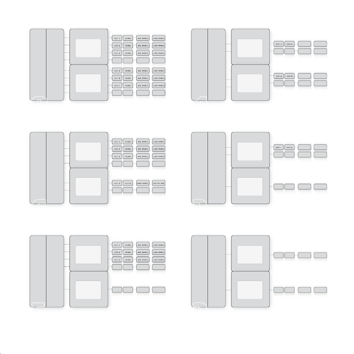
1. Connections
Before you make any connections, always disconnect the battery!
1.1 First of all, connect the RCA cables coming from the radio/headunit
to the respective inputs of your amplifier. Always run signal cables in
a distance to power cables and the vehicle´s factory wires to avoid
induction of noise.
1.2 Now the speaker wires must be connected to the respective speaker
terminals. Please make sure to use speakers with the correct imped-
ance! Also make sure to connect all speakers with correct polarity
to avoid phase problems which can spoil the sound of the whole
system.
1.3 Next step is the ground connection. Check for a good grounding
point using your vehicle´s chassis. Make sure that this point has
good electrical contact! Some parts of the chassis might only be
glued and have no contact to battery (-). Run all ground cables of
the system to this point to avoid alternator whine and other noise.
1.4 As the next connection the +12 V cable has to be connected to the
(+) terminal of the battery. Always be careful not to run this cable
around sharp edges, the insulation might be damaged. For holes
always use grommets!
Always use an in-line fuse in the +12 V power cable in max. 12“
from the battery´s + terminal (value must meet the current require-
ments of the whole sound system,minimum value is 80 A).
1.5 The last connection is the remote wire. The headunit must always
be turned off during this connection, as it might be damaged when
remote output is shorted to ground! Now you can reconnect the
battery and insert the main fuse into the power cable´s fuse holder.
Caution:
Both, the +12 V and the ground cable, must have sufficient diameter!
XETEC proposes the following minimum gauges:
Total output power of the system:
Up to 100 W : 6 mm
Up to 250 W : 8 mm
Up to 500 W : 10 mm
Up to 750 W : 25 mm
Up to 1000 W : 35 mm
Up to 1200 W : 40 mm
more than 1200 W : 50 mm
Weaker Cables will reduce the performance of your system significantly,
and may cause damage to your amplifiers. Weak cables also will heat-up!
To stabily your suply against short impulses we recommend a Capacitor
(only wizh integrated protection System) which you can connect directly
to the Amplifiers Power Suply system by using the “EXT Cap Terminals”.
The usage of a Power Capacitor is strongly recommended for that part
of the amp which is suplying the subwoofers. Please also referr to the
installation guide of the capacitors manufacturer.
Caution
Always replace fuses with same value. Higher values may cause damage
to your amplifier, battery or car!
2. First power-on
2.1 Adjust all level controls to minimum
2.2 Turn on the radio at low volume
2.3 Increase the volume and adjust the front speaker’s volume
2.4 Now adjust the volume ratio between front and rear speakers and
subwoofer.

– 7 –
– 7 –
XETEC recommends the following crossover frequencies:
16 cm front speaker: 16 cm rear speaker:
Highpass 80-100 Hz Highpass 100-120 Hz
13 cm front speaker: 13 cm rear speaker:
Highpass 100-140 Hz Highpass 120-150 Hz
13 cm front speaker: 10 cm rear speaker:
Highpass 120-200 Hz Highpass 150-200 Hz
16 cm midbass: Bandpass 80/150 Hz
Highpass 80 Hz + Lowpass 150Hz
Composystems then are run with Highpass 150-180 Hz!
Subwoofer: Lowpass 70-100 Hz, Subsonic 20-35 Hz
3. Controls
All controls are accessible under the aluminium top cover. For adjust-
ments, remove the top cover using the hexa screwdriver that came with
your product. You will find all 8 gain controls, depending on the configu-
ration of the Ampilifier some may be without function (eg if Channels
1-4 are used in parabridge mode only the gain control of channel 1 is
used and those of channels 2-4 are without function)
4. Connectors (Gravity 8G-1000)
1. Speaker terminals of channels 1-4
2. RCA line inputs
3. Speaker terminals of channels 5-8
4. Terminal for external capacitor of channel 5-8
5. Fuse of channel 5-8
6. 12V power suply and ground connection
7. Remote input
8. Fuse of channel 1-4
9. Terminal for external capacitor of channel 1-4
Before you open the amplifier to exchange the modules, make sure that
it is switched off! Damage will occur to your speakers and amplifier, if
the module is exchanged during operation!
Applied technologies:
· HPAA© by XETEC design group GmbH: „High Precision Analog
Amplifier“, symmetrical State-of-the-Art power amplifier.
· X-SMPS© by XETEC design group GmbH: „x-Switched-Mode-
Power-Supply“, high efficiency power supply
· X-protect © by XETEC design group GmbH: Highly sensitive
protection circuits
· ParaBridge Mode © by XETEC design group GmbH: crossconection
of 4 Amplifiers to one.

– 8 –
Technical data
RMS Output power in single mode @ 4 Ohms: 8 x 83 Watts
RMS Output power in single mode @ 2 Ohms: 8 x 130 Watts
RMS Output power in bridge mode @ 4 Ohms: 4 x 260 Watts
RMS Output power in parabridge mode @4 Ohms: 2 x 330 Watts
RMS Output power in parabridge mode @2 Ohms: 2 x 520 Watts
Peak output power: >1500 Watts total
Max input Current (@13,8 V): 100 A
Idle current (no signal): 1,2 A
Fuse: 2x40 A
Total Harmonic Distortion (THD): <0,05 %
SNR: >89 dB(A)
Freq.Response (bypass mode): 7 Hz-50.000 Hz
Stability (single/bridge/parabridge): 2 /4 /2 Ohms
Input Sensitivity: 250 mV-6 V
Warranty: 1 Year
Troubleshooting
1. Power indicator LED in top plate is not lit
· Main fuse or fuse in amplifier blown?
· Remote wire properly connected? Is there remote voltage (12 V)?
· Amplifier overheated?
2. Power indicator LED in top plate lights RED
· Protection active. Check the speakers and speaker wires for short-
circuit!
· Battery voltage low (<10,2 V)?
· DC on one of the speaker outputs?
· Overload
3. Distortions at medium level
· Please check the speaker connections for short-circuits
· Are the speakers OK?
· Radio volume turned up too high. Better turn up the amplifier’s level
controls
4. Alternator whine and similar noise
· Bad ground connections?
· Use ONE ground contact only!
· RCA cables run too close to power cables?
In case of further trouble, please ask your local XETEC dealer for
support.
Table of contents
Other XETEC Amplifier manuals
Popular Amplifier manuals by other brands

NAD
NAD M2 - CONNECTING A SUBWOOFER Service manual

Pro-Ject Audio Systems
Pro-Ject Audio Systems Pro-Ject MaiA DS Instructions for use

Audio Research
Audio Research VS115 owner's manual

Cambridge Audio
Cambridge Audio Azur 540A V2 Technical specifications

Ibanez
Ibanez IBZ15GR owner's manual

GLEMM
GLEMM PAA 90BM instruction manual

Advance acoustic
Advance acoustic MAP-101 owner's manual

D'Amore engine'ring
D'Amore engine'ring E Series owner's manual

Esoteric
Esoteric Esoteric A-100 owner's manual

Conrad-Johnson
Conrad-Johnson Premier Four owner's manual

TECshow
TECshow CONCERT SERIES user manual

Dan D'Agostino
Dan D'Agostino Momentum owner's manual