Xilinx Alveo U200 User manual

Revision History
The following table shows the revision history for this document.
Section Revision Summary
11/20/2019 Version 1.1.1
General updates. Editorial updates only. No technical content updates.
10/31/2019 Version 1.1
All sections. Updated to the Vitis™ unified software platform throughout.
02/15/2019 Version 1.0
Initial Xilinx release. N/A
Revision History
UG1289 (v1.1.1) November 20, 2019 www.xilinx.com
Alveo U200 and U250 Accelerator Cards 2
Send Feedback

Table of Contents
Revision History...............................................................................................................2
Chapter 1: Introduction.............................................................................................. 5
Block Diagram..............................................................................................................................7
Card Features...............................................................................................................................7
Card Specifications......................................................................................................................9
Design Flows................................................................................................................................ 9
Chapter 2: Card Installation and Configuration......................................... 14
Electrostatic Discharge Caution...............................................................................................14
Installing Alveo Data Center Accelerator Cards in Server Chassis......................................14
FPGA Configuration...................................................................................................................15
Chapter 3: Card Component Description........................................................ 16
UltraScale+ FPGA....................................................................................................................... 16
DDR4 DIMM Memory................................................................................................................16
Quad SPI Flash Memory........................................................................................................... 16
USB JTAG Interface.................................................................................................................... 17
FT4232HQ USB-UART Interface............................................................................................... 17
PCI Express Endpoint................................................................................................................17
QSFP28 Module Connectors.................................................................................................... 18
I2C Bus........................................................................................................................................18
Status LEDs.................................................................................................................................19
Card Power System................................................................................................................... 19
Appendix A: Xilinx Design Constraints (XDC) File...................................... 20
Appendix B: Regulatory and Compliance Information........................... 21
CE Directives.............................................................................................................................. 21
CE Standards..............................................................................................................................21
Compliance Markings............................................................................................................... 22
Appendix C: Additional Resources and Legal Notices............................. 23
UG1289 (v1.1.1) November 20, 2019 www.xilinx.com
Alveo U200 and U250 Accelerator Cards 3
Send Feedback

Xilinx Resources.........................................................................................................................23
Documentation Navigator and Design Hubs.........................................................................23
References..................................................................................................................................23
Please Read: Important Legal Notices................................................................................... 25
UG1289 (v1.1.1) November 20, 2019 www.xilinx.com
Alveo U200 and U250 Accelerator Cards 4
Send Feedback

Chapter 1
Introduction
IMPORTANT! Except where noted, this user guide applies to both the U200 and U250 cards.
The Xilinx® Alveo™ U200/U250 Data Center accelerator cards are peripheral component
interconnect express (PCIe®) Gen3 x16 compliant cards featuring the Xilinx Virtex® UltraScale+™
technology. These cards accelerate compute-intensive applicaons such as machine learning,
data analycs, video processing, and more. The Alveo U200/U250 Data Center accelerator cards
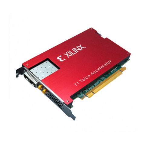
are available in passive and acve cooling conguraons. The following gure shows a passively
cooled Alveo U200 accelerator card.
UG1289 (v1.1.1) November 20, 2019 www.xilinx.com
Alveo U200 and U250 Accelerator Cards 5
Send Feedback

Figure 1: Alveo U200 Data Center Accelerator Card (Passive Cooling)
X23434-102419
CAUTION! The Alveo U200/U250 accelerator card with passive cooling is designed to be installed into a data
center server, where controlled air ow provides direct cooling. Due to the card enclosure, switches are not
accessible and LEDs are not visible (except for the triple-LED module DS3 that protrudes through the le front
end PCIe bracket). The card details in this user guide are provided to aid understanding of the card features. If
the cooling enclosure is removed from the card and the card is powered-up, external fan cooling airow MUST
be applied to prevent over-temperature shut-down and possible damage to the card electronics. Removing the
cooling enclosure voids the board warranty.
See Appendix C: Addional Resources and Legal Noces for references to documents, les, and
resources relevant to the Alveo U200/U250 accelerator cards.
Chapter 1: Introduction
UG1289 (v1.1.1) November 20, 2019 www.xilinx.com
Alveo U200 and U250 Accelerator Cards 6
Send Feedback

Block Diagram
The block diagram of the Alveo U200/U250 accelerator card is shown in the following gure.
Figure 2: Card Block Diagram
Clocks
U200: XCU200 D2104
U250: XCU250 D2104
PCIe GEN1/2/3 x 1/2/4/8/16
QSFP #2
XADC
LEDs
QSFP #1
QSPI
Power
288-pin DIMM interface
64-bit + ECC dual rank support
x4/x8 UDIMM support
PC4-2400 compatible
C0
288-pin DIMM interface
64-bit + ECC dual rank support
x4/x8 UDIMM support
PC4-2400 compatible
C2
288-pin DIMM interface
64-bit + ECC dual rank support
x4/x8 UDIMM support
PC4-2400 compatible
C3
288-pin DIMM interface
64-bit + ECC dual rank support
x4/x8 UDIMM support
PC4-2400 compatible
C1
X23433-102419
Card Features
The Alveo U200/U250 accelerator card features are listed in this secon. Detailed informaon
for each feature is provided in Chapter 3: Card Component Descripon.
• Alveo U200 accelerator card:
○Virtex UltraScale+ XCU200-2FSGD2104E FPGA
• Alveo U250 accelerator card:
○Virtex UltraScale+ XCU250-2LFIGD2104E FPGA
Chapter 1: Introduction
UG1289 (v1.1.1) November 20, 2019 www.xilinx.com
Alveo U200 and U250 Accelerator Cards 7
Send Feedback

• Memory (four independent dual-rank DDR4 interfaces)
○64 gigabyte (GB) DDR4 memory
○4x DDR4 16 GB, 2400 mega-transfers per second (MT/s), 64-bit with error correcng code
(ECC) DIMM
○x4/x8 unregistered dual inline memory module (UDIMM) support
•Conguraon opons
○1 gigabit (Gb) Quad Serial Peripheral Interface (SPI) ash memory
○Micro-AB universal serial bus (USB) JTAG conguraon port
• 16-lane PCI Express
• Two QSFP28 connectors 100G interfaces
• USB-to-UART FT4232HQ bridge with Micro-AB USB connector
• PCIe Integrated Endpoint block connecvity
○Gen1, 2, or 3 up to x16
• I2C bus
• Status LEDs
• Power management with system management bus (SMBus) voltage, current, and temperature
monitoring
• Dynamic power sourcing based on external power supplied
• 65W PCIe slot funconal with PCIe slot power only
• 150 W PCIe slot funconal with 110 A max VCCINT current PCIe slot power and 6-pin PCIe
AUX power cable connected
• 225 W PCIe slot funconal with 160 A max VCCINT current PCIe slot power and 8-pin PCIe
AUX power cable connected
• Onboard reprogrammable ash conguraon memory
• Front panel JTAG and universal asynchronous receiver-transmier (UART) access through the
USB port
• FPGA congurable over USB/JTAG and Quad SPI conguraon ash memory
Chapter 1: Introduction
UG1289 (v1.1.1) November 20, 2019 www.xilinx.com
Alveo U200 and U250 Accelerator Cards 8
Send Feedback

Card Specifications
Dimensions
Height: 4.376 inch (11.115 cm)
PCB thickness (±5%): 0.062 inch (0.157 cm)
Card length, passive heat sink: 9.2 inch (23.4 cm)
Card thickness with heat sink enclosure installed:
Passive: 1.44 inch (3.66 cm)
Note: A 3D model of this card is not available.
Environmental
Temperature
Operang: 0°C to +45°C
Storage: –25°C to +60°C
Humidity
10% to 90% non-condensing
Operating Voltage
PCIe® slot +12 VDC, +3.3 VDC, +3.3 VAUXDC, External +12 VDC
Design Flows
The preferred opmal design ow for targeng the Alveo Data Center accelerator card uses the
Vis™ unied soware plaorm. However, tradional design ows, such as RTL or HLx are also
supported using the Vivado® Design Suite tools. The following gure shows a summary of the
design ows.
Chapter 1: Introduction
UG1289 (v1.1.1) November 20, 2019 www.xilinx.com
Alveo U200 and U250 Accelerator Cards 9
Send Feedback

Figure 3: Alveo Data Center Accelerator Card Design Flows
High complexity
Slowest
High
Simplicity
Time to Market
Hardware Expertise Required
Complexity abstracted
Fastest
Low
RTL Flow HLx Flow (IP integrator)
Traditional Flows
Target Platform
Vitis
X22272-020419
Requirements for the dierent design ows are listed in the following table.
Table 1: Requirements to Get Started with Alveo Data Center Accelerator Card Design
Flows
RTL Flow HLx Flow Vitis
Flow documentation UG9491UG8952UG13013
Hardware documentation UG1289 UG1289 N/A
Vivado tools support Board support XDC Board support XDC N/A
Programming the FPGA Vivado Hardware Manager Vivado Hardware Manager
Notes:
1. UltraFast Design Methodology Guide for the Vivado Design Suite (UG949).
2. Vivado Design Suite User Guide: System-Level Design Entry (UG895). See “Using the Vivado Design Suite Platform Board
Flow” in Chapter 2 and Appendix A.
3. Getting Started with Alveo Data Center Accelerator Cards (UG1301).
For either the RTL or HLx ow, designers can start by targeng the Alveo Data Center
accelerator card in the Vivado® tools. In the Vivado Design Suite, select Create New Project →
RTL Project, and then select the Alveo Data Center accelerator U200 card as shown in the
following gure.
Chapter 1: Introduction
UG1289 (v1.1.1) November 20, 2019 www.xilinx.com
Alveo U200 and U250 Accelerator Cards 10
Send Feedback

Figure 4: Selecting Alveo Data Center Accelerator U200 Card in Vivado Design Suite
X22260-012919
When using the RTL ow, aer you have selected the Alveo Data Center accelerator card from
the Boards tab, the following gures appear. The RTL-based project can now be created.
Figure 5: Alveo Data Center Accelerator U200 Card New Project Summary
X22261-012519
Chapter 1: Introduction
UG1289 (v1.1.1) November 20, 2019 www.xilinx.com
Alveo U200 and U250 Accelerator Cards 11
Send Feedback

Figure 6: Alveo Data Center Accelerator U200 Card New Project Summary
X22262-012519
Creating an MCS File and Programming the Alveo
Card
For custom RTL ow, this secon outlines the procedures to do the following:
• Create an MCS le (PROM image)
• Flash programming through the USB-JTAG (Micro USB) interface
Create an MCS File (PROM Image)
The Alveo accelerator card contains a Quad SPI conguraon ash memory part that can be
congured over USB-JTAG. This part contains a protected region, with the factory base image at
the 0x00000000 address space. This base image points to the customer programmable region at
a 0x01002000 address space oset.
To ensure that the PROM image is successfully loaded onto the Alveo accelerator card at power
on, the starng address must be set to 0x01002000 and the interface set to spix4 when
creang the MCS le. Details on adding this to the MCS le can be found in the UltraScale
Architecture Conguraon User Guide (UG570).
Chapter 1: Introduction
UG1289 (v1.1.1) November 20, 2019 www.xilinx.com
Alveo U200 and U250 Accelerator Cards 12
Send Feedback

In addion, the following code must be placed in the project XDC le to correctly congure the
MCS le.
# Bitstream Configuration
# ------------------------------------------------------------------------
set_property CONFIG_VOLTAGE 1.8 [current_design]
set_property BITSTREAM.CONFIG.CONFIGFALLBACK Enable [current_design]
set_property BITSTREAM.GENERAL.COMPRESS TRUE [current_design]
set_property CONFIG_MODE SPIx4 [current_design]
set_property BITSTREAM.CONFIG.SPI_BUSWIDTH 4 [current_design]
set_property BITSTREAM.CONFIG.CONFIGRATE 85.0 [current_design]
set_property BITSTREAM.CONFIG.EXTMASTERCCLK_EN disable [current_design]
set_property BITSTREAM.CONFIG.SPI_FALL_EDGE YES [current_design]
set_property BITSTREAM.CONFIG.UNUSEDPIN Pullup [current_design]
set_property BITSTREAM.CONFIG.SPI_32BIT_ADDR Yes [current_design]
# ------------------------------------------------------------------------
Program the Alveo Card
Aer the MCS le is created, see the procedure in the "Programming the FPGA Device" chapter
in the Vivado Design Suite User Guide: Programming and Debugging (UG908) to connect to the
Alveo Data Center accelerator card using the hardware manager.
1. Select Add Conguraon Device and select the mt25qu01g-spi-x1_x2_x4 part.
2. Right-click the target to select Program the Conguraon Memory Device.
a. Select the MCS le target.
b. Select Conguraon File Only.
c. Click OK.
3. Aer programming has completed, disconnect the card in the hardware manager, and
disconnect the USB cable from the Alveo accelerator card.
4. Perform a cold reboot on the host machine to complete the card update.
Chapter 1: Introduction
UG1289 (v1.1.1) November 20, 2019 www.xilinx.com
Alveo U200 and U250 Accelerator Cards 13
Send Feedback

Chapter 2
Card Installation and Configuration
Electrostatic Discharge Caution
CAUTION! ESD can damage electronic components when they are improperly handled, and can result in total
or intermient failures. Always follow ESD-prevenon procedures when removing and replacing components.
To prevent ESD damage:
• Use an ESD wrist or ankle strap and ensure that it makes skin contact. Connect the equipment
end of the strap to an unpainted metal surface on the chassis.
• Avoid touching the adapter against your clothing. The wrist strap protects components from
ESD on the body only.
• Handle the adapter by its bracket or edges only. Avoid touching the printed circuit board or
the connectors.
• Put the adapter down only on an anstac surface such as the bag supplied in your kit.
• If you are returning the adapter to Xilinx Product Support, place it back in its anstac bag
immediately.
Installing Alveo Data Center Accelerator
Cards in Server Chassis
Because each server or PC vendor's hardware is dierent, for physical board installaon
guidance, see the manufacturer’s PCI Express® board installaon instrucons.
For programming and start-up details, see Geng Started with Alveo Data Center Accelerator Cards
(UG1301).
Chapter 2: Card Installation and Configuration
UG1289 (v1.1.1) November 20, 2019 www.xilinx.com
Alveo U200 and U250 Accelerator Cards 14
Send Feedback

FPGA Configuration
The Alveo U200/U250 accelerator card supports two UltraScale+™ FPGA conguraon modes:
• Quad SPI ash memory
• JTAG using USB JTAG conguraon port (USB J13/FT4232H U27)
The FPGA bank 0 mode pins are hardwired to M[2:0] = 001 master SPI mode with pull-up/down
resistors.
At power up, the FPGA is congured by the Quad SPI NOR ash device (Micron
MT25QU01GBBA8E12-0SIT) with the FPGA_CCLK operang at clock rate of 105 MHz
(EMCCLK) using the master serial conguraon mode. The Quad SPI ash memory NOR device
has a capacity of 1 Gb.
If the JTAG cable is plugged in, QSPI conguraon might not occur. JTAG mode is always
available independent of the mode pin sengs.
For complete details on conguring the FPGA, see the UltraScale Architecture Conguraon User
Guide (UG570).
Table 2: Configuration Modes
Configuration Mode M[2:0] Bus Width CCLK Direction
Master SPI 001 x1, x2, x4 FPGA output
JTAG Not applicable – JTAG overrides x1 Not applicable
Chapter 2: Card Installation and Configuration
UG1289 (v1.1.1) November 20, 2019 www.xilinx.com
Alveo U200 and U250 Accelerator Cards 15
Send Feedback

Chapter 3
Card Component Description
This chapter provides a funconal descripon of the components of the Alveo™ U200/U250
Data Center accelerator card.
UltraScale+ FPGA
The Alveo U200 accelerator card is populated with the Virtex® UltraScale+™ XCU200-
L2FSGD2104E FPGA.
The Alveo U250 accelerator card is populated with the Virtex UltraScale+ XCU250-
L2FIGD2104E FPGA.
For more informaon about Virtex® UltraScale+™ FPGAs, see the Virtex UltraScale+ FPGA Data
Sheet: DC and AC Switching Characteriscs (DS923).
DDR4 DIMM Memory
Four independent dual-rank DDR4 interfaces are available. The card is populated with four
socketed single-rank Micron MTA18ASF2G72PZ-2G3B1IG 16GB DDR4 RDIMMs. Each DDR4
DIMM is 72 bits wide (64-bits plus support for ECC).
The detailed FPGA and DIMM pin connecons for the feature described in this secon are
documented in the Alveo U200/U250 accelerator card XDC le.
For more details about the Micron DDR4 DIMM, see the Micron MTA18ASF2G72PZ-2G3B1IG
data sheet at the Micron website: hp://www.micron.com.
Quad SPI Flash Memory
The Quad SPI device provides 1 Gb of nonvolale storage.
• Part number: MT25QU01GBBB8E12-0SIT (Micron)
Chapter 3: Card Component Description
UG1289 (v1.1.1) November 20, 2019 www.xilinx.com
Alveo U200 and U250 Accelerator Cards 16
Send Feedback

• Supply voltage: 1.8V
• Datapath width: 4 bits
• Data rate: variable
For more ash memory details, see the Micron MT25QU01GBBB8E12-0SIT data sheet at the
Micron website.
For conguraon details, see the UltraScale Architecture Conguraon User Guide (UG570). The
detailed FPGA and Flash pin connecons for the feature described in this secon are
documented in the Alveo U200/U250 accelerator card XDC le, referenced in Appendix A: Xilinx
Design Constraints (XDC) File.
USB JTAG Interface
The Alveo accelerator card provides access to the FPGA device via the JTAG interface.
FPGA conguraon is available through the Vivado® hardware manager, which accesses the on-
board USB-to-JTAG FT4232HQ bridge device. The micro-AB USB connector on the Alveo U200/
U250 accelerator card PCIe® panel/bracket provides external device programming access.
Note: JTAG conguraon is allowed at any me regardless of the FPGA mode pin sengs consistent with
the UltraScale Architecture Conguraon User Guide (UG570).
For more details about the FT4232HQ device, see the FTDI website: hps://www.dichip.com/.
FT4232HQ USB-UART Interface
The FT4232HQ Quad USB-UART provides a UART connecon through the micro-AB USB
connector. The FPGA UART TX/RX (two-wire) connecon is made through the FT4232HQ BD
port. Channel BD implements a 2-wire level-shied TX/RX UART connecon to the FPGA. The
FTDI FT4232HQ data sheet is available on the FTDI website: hps://www.dichip.com/.
PCI Express Endpoint
The Alveo U200/U250 accelerator card implements a 16-lane PCI Express® edge connector that
performs data transfers at the rate of 2.5 giga-transfers per second (GT/s) for Gen1, 5.0 GT/s for
Gen2, and 8.0 GT/s for Gen3 applicaons. The -2 speed grade FPGA included with the cards
supports up to Gen3 x16.
Chapter 3: Card Component Description
UG1289 (v1.1.1) November 20, 2019 www.xilinx.com
Alveo U200 and U250 Accelerator Cards 17
Send Feedback

QSFP28 Module Connectors
The Alveo accelerator cards host two 4-lane small form-factor pluggable (QSFP) connectors that
accept an array of opcal modules. Each connector is housed within a single QSFP cage
assembly.
The QSFP+ connectors are accessible via the I2C interface on the Alveo U200/U250 accelerator
cards. The QSFP connector’s sideband signals are accessible directly from the FPGA. The
MODSELL, RESETL, MODPRSL, INTL, and LPMODE sideband signals are dened in the small
form factor (SFF) specicaons listed below. The components visible through the card PCIe
panel/bracket top to boom are:
• Triple status LEDs
• QSFP0
• QSFP1
• USB
For addional informaon about the quad SFF pluggable (28 Gb/s QSFP+) module, see the
SFF-8663 and SFF-8679 specicaons for the 28 Gb/s QSFP+ at the SNIA Technology Aliates
website: hps://www.snia.org/s/specicaons2.
Each QSFP connector has its own clock generator.
• QSFP0 clock
○Clock generator: Silicon Labs SI5335A-B06201-GM
○Output CLK1A/1B: the QSFP0_CLOCK_P/N clock is an AC-coupled LVDS 156.25 MHz
clock wired to the QSFP0 GTY interface
• QSFP1 clock
○Clock generator: Silicon Labs SI5335A-B06201-GM
○Output CLK1A/1B: the QSFP1_CLOCK_P/N clock is an AC-coupled LVDS 156.25 MHz
clock wired to the QSFP1 GTY interface
The detailed FPGA and QSFP pin connecons for the feature described in this secon are
documented in the Appendix A: Xilinx Design Constraints (XDC) File.
I2C Bus
The Alveo U200/U250 accelerator cards implement an I2C bus network (the device tree details
are available in the board support package).
Chapter 3: Card Component Description
UG1289 (v1.1.1) November 20, 2019 www.xilinx.com
Alveo U200 and U250 Accelerator Cards 18
Send Feedback

Status LEDs
The Alveo card is designed to operate with the passive heat sink enclosure cover installed so the
DS1 and DS2 LEDs are not visible. Status light eming diodes (LEDs) DS3, DS4, and DS5 are
visible through a cutout in the PCIe end bracket. The following table denes the card status
LEDs.
Table 3: Card Status LEDs
Reference Designator Description
DS1 RED: POWER_GOOD
DS2 BLUE: DONE_0
DS3 ORANGE: STATUS_LED0
DS4 YELLOW: STATUS_LED1
DS5 GREEN: STATUS_LED2
Card Power System
Limited power system telemetry is available through the I2C IP. I2C IP is instanated during the
FPGA design process which begins aer the Alveo Data Center accelerator card is selected from
the Vivado Design Suite Boards tab. Refer to Design Flows for more informaon.
Chapter 3: Card Component Description
UG1289 (v1.1.1) November 20, 2019 www.xilinx.com
Alveo U200 and U250 Accelerator Cards 19
Send Feedback

Appendix A
Xilinx Design Constraints (XDC) File
RTL users can reference the Vivado Design Suite User Guide: Using Constraints (UG903) for more
informaon. The Alveo accelerator card XDC les are available for download from their
respecve websites along with this user guide.
Appendix A: Xilinx Design Constraints (XDC) File
UG1289 (v1.1.1) November 20, 2019 www.xilinx.com
Alveo U200 and U250 Accelerator Cards 20
Send Feedback
Other manuals for Alveo U200
4
This manual suits for next models
1
Table of contents
Other Xilinx Video Card manuals