Xo 250 User manual


3
WWW.XOBOATS.FI
XO BOAT S
FOREWORD
Dear XO boat owner, thank you for selecting the XO, a superb boat
made in Finland. We wish you enjoy your time on the waves.
The purpose of this manual is to help you learn to use your boat
safely and comfortably. The following chapters will provide a detai-
led account of the systems and equipment of your boat as well as
information about its use and maintenance. We strongly recom-
mend that you read the manual carefully and get to know your boat
before launching it. Naturally, this owner’s manual does not provide
the seamanship or boating safety skills necessary for operating a
boat. For your own safety and comfort, if the XO is your first boat
or you are not yet familiar with this specific boat type, we recom-
mend getting some experience in handling and operating the boat
before taking command. Your boat dealer as well as boat clubs and
national motor boat and yacht associations are more than happy
to tell you about local boat training programmes and recommend
competent teachers. Please make sure that the current wind and
swell conditions correspond to your boat’s design category and that
you and your crew are able to control the boat in the conditions.
The wind and swell conditions corresponding to design category C
range from storm conditions to high winds with the risk of excep-
tionally strong gusts and high waves. Such conditions are dange-
rous and only competent and fit crews using a well-maintained boat
should face them. This owner’s manual is not intended as a detailed
maintenance or troubleshooting guide. If you have any problems
with the boat, please contact your XO dealer. For repairs, please use
only companies recommended by the XO dealer.
PLEASE STORE THIS MANUAL IN A SAFE PLACE AND PASS IT
OVER TO THE NEXT OWNER WHEN YOU SELL THE BOAT.

4 5
CONTENTS
1 BEFORE YOU GO 9
2 GENERAL 11
3 WARRANTY 12
4 BEFORE PUTTING THE BOAT IN SERVICE 12
4.1 Registration 12
4.2 Insurance 12
4.3 Training 12
5 BOAT PROPERTIES AND OPERATION 13
5.1 General 13
5.2 Basic specifications 13
5.3 Maximum recommended number of persons 13
5.4 Loading 14
5.5 Engine and propeller 14
5.6 Stability and preventing water intake 14
5.6.1 Openings in hull and deck 14
5.6.2 Bilge pumps and draining 14
5.6.3 Stability, buoyancy and flotation 17
5.7 Fire or explosion risk prevention 17
5.7.1 Engines and fuel systems 17
5.7.2 Fire protection and prevention 18
5.8 Electrical system 19
5.9 Steering properties 23
5.9.1 Driving at high speeds 23
5.9.2 Emergency switch 24
5.9.3 Visibility from the steering position 24
5.10 Correct use – other recommendations
and instructions 25
5.10.1 Protection from falling overboard
and means of reboarding 25
5.10.2 Securing loose equipment 25
5.10.3 Environmental considerations 25
5.10.4 Anchoring, mooring and towing 27
5.10.5 Trailer transport 29
5.10.6 Navigation 29
6 MAINTENANCE, REPAIRS AND WINTER STORAGE 30
7 OPTIONAL ACCESSORIES 31
7.1 General 31
7.2 Installing optional accessories 31
7.2.1 Radio/CD player 31
APPENDIX 1 TECHNICAL SPECIFICATIONS 33
APPENDIX 2 XO 250 OPEN / GENERAL ARRANGEMENT 35
APPENDIX 3 GENERAL REQUIREMENTS 36
APPENDIX 4 ELECTRICAL WIRING DIAGRAM 37

7
BOAT MODEL: XO 250 OPEN
Craft identification number - CIN:
Engine make and model:
Engine serial number:
I OWNER
First name:
Surname:
Municipality of domicile:
Year of purchase:
II OWNER
First name:
Surname:
Municipality of domicile:
Year of purchase:
III OWNER
First name:
Surname:
Municipality of domicile:
Year of purchase:
IV OWNER
First name:
Surname:
Municipality of domicile:
Year of purchase:
V OWNER
First name:
Surname:
Municipality of domicile:
Year of purchase:
VI OWNER
First name:
Surname:
Municipality of domicile:
Year of purchase:

9
1 BEFORE YOU GO
Please read this owner’s manual.
Before taking your boat out on the water, check at least the follo-
wing:
Current weather and weather forecast
Consider whether the wind, swell and visibility conditions are sui-
table. Is the boat’s design category, size and equipment as well as
the commander’s and the crew’s proficiency sucient for the inten-
ded waters?
Loading
Do not overload the boat, distribute the load appropriately. Do not
place heavy items too high, since this would compromise the boat’s
stability.
Passengers
Make sure to include life jackets for all persons onboard. Assign the
tasks required during the trip together before setting o.
Fuel
Check that there is sucient fuel as well as an additional reserve in
case of poor weather or other adverse conditions. Reserve at least
20 percent more fuel than required in case of exceptional and unfo-
reseen circumstances.
Engine and equipment
Check the operation and condition of steering, electrical devices and
battery, and perform all daily inspection procedures specified in the
engine manual. Check that the boat is seaworthy in other ways: no
fuel or water leaks, safety equipment is onboard, etc. Check that the
bilge water level is at minimum.
Ventilation
To reduce the risk of fire, make sure that areas where fuel is sto-
red are ventilated.
Securing loose items
Check that all loose items have been secured so that they will stay
in place also in heavy swell and wind.
Nautical charts
If you are not completely familiar with the route, does your nautical
chart cover a sucient area?
Unberthing maneuvers
Decide with your crew who takes care of what, for example, who
detaches which line. Check that the mooring or other lines do not
get tangled in the propeller during berthing or unberthing.
REFER TO THE SEPARATE ENGINE MANUAL FOR ADDITIONAL
INSTRUCTIONS ON THE ENGINE.

11
2 GENERAL
The owner’s manual will help you learn the properties of your new
boat. Additional manuals for equipment installed in the boat are
also attached, and will be referred to throughout this manual. If you
decide to purchase optional accessories, the manual will, of course,
be complemented with their manuals. There is also space for your
own notes at the end of the manual.
The following warning and caution notices appear in this manual
and are defined as follows:
DANGER!
If appropriate precautions are not taken, there is a serious risk
which will very probably lead to death or permanent injury.
CAUTION!
If the appropriate precautions are not taken, there is a serious
risk of injury or death.
NOTE!
This text reminds users of safe conduct or indicates dangerous
actions which may lead to injury to persons or damage to the boat
or its components.
All units used in this manual correspond to the SI system. In some
cases, additional units have been included in brackets. The excep-
tion to the above is wind speed, which is indicated according to the
Beaufort scale as required by the EC Recreational Craft Directive.

12 13
3 WARRANTY
This boat and the equipment installed by the boatbuilder are cove-
red by a warranty as specified in detail below. The engine, trim tabs,
compass, any navigation devices and other retrofitted devices are
subject to any warranty of their respective manufacturers. Sepa-
rate warranty cards for these devices and appropriate supplier infor-
mation are included as an attachment. For other warranty issues,
please contact your XO dealer indicated on the front cover.
4 BEFORE PUTTING THE BOAT
IN SERVICE
4.1 REGISTRATION
In many countries, even small motor boats must be registered.
Ask the local authorities about the registration provisions in your
country of residence. Typically, there is also a minimum age requi-
rement for operating registered craft. A separate boat operators
license may also be required.
4.2 INSURANCE
A boat insurance may compensate for damage occurring on water
and during transport. Check the coverage especially before lifting
the boat o water. The insurance may also have an indirect eect
on safety on water: if there is a shipwreck, you will be able to focus
specifically on saving lives. Insurance companies will provide detai-
led information of the dierent insurance options available.
4.3 TRAINING
There is a wide range of boating literature available, and boat clubs
and navigation courses are an excellent source of useful and practi-
cal boating information. These provide a solid base for your boating
skills, but proficiency in boat handling, navigation, mooring and
anchoring can be achieved only through extensive practical training.
5 BOAT PROPERTIES AND OPERATION
5.1 GENERAL
The owner’s manual is not intended as a complete maintenance guide
or repair manual; instead, its purpose is to help the user get familiar
with the properties of the boat and operate the boat appropriately.
5.2 BASIC SPECIFICATIONS
The basic specifications of the XO 250 Open are as follows:
Boat type: XO 250 Open
Design category: C (inshore)
Maximum allowed load: 848 kg
Please refer also to section 5.4: Loading
Design category C is defined as follows:
Category C: the boat is designed for voyages in waters where condi-
tions up to, and including, wind force 6 (approx. 14 m/s) and signifi-
cant wave heights up to, and including, 2 m (infrequently up to 4 m)
may be experienced. These conditions may occur in coastal waters,
estuaries, open lakes and rivers in reasonable weather conditions.
NOTE!
The significant wave height is the mean height of the top third
of the swell, which corresponds closely to the wave height esti-
mate of an experienced observer. Some individual waves may be
twice as high.
Main dimensions and capacity:
Boat length, beam, draught, total weight and other dimensions as
well as tank capacities are indicated in appendix 1. Technical spe-
cifications.
Builder’s plate:
Attached close to the steering position, the builder’s plate inclu-
des some of the above information. Supplementary information
has been provided in relevant parts of this manual. Please note that
unlike the manufacturer’s recommended maximum load, the maxi-
mum load specified in the builder’s plate does not include fuel. The
load specified in the plate is 675 kg, which includes the weight of
persons (600 kg) and other stowage (75 kg).
5.3 MAXIMUM RECOMMENDED NUMBER OF PERSONS
The maximum recommended number of persons for the boat is 8.
The location of their seats are indicated in figure 1.
CAUTION!
The recommended number of persons must not be exceeded.
Regardless of the total number of persons onboard, the total
weight of the persons and the stowage must not exceed the max-
imum recommended load (see section 5.4: Loading). Always use
the seats provided in the boat. If the boat is not equipped with
seats for seven passengers, the rest must sit on the deck in posi-
tions indicated in the figure.

14 15
5.4 LOADING
The maximum recommended load for the XO 250 Open is 848 kg.
An adult person is considered to weigh 75 kg and child 37,5 kg. The
maximum total weight of persons onboard is 600 kg. In addition to
the maximum recommended total weight of persons, the boat can
be loaded with the following: basic equipment (25 kg) and fuel inten-
ded for consumption stored in the fixed fuel tank (175 kg). Only the
above weight components are included in the recommended load.
CAUTION!
When loading the boat, do not exceed the maximum recommen-
ded load. Always load the boat carefully and distribute the load
appropriately so that the design water line is retained (close to
even keel). Avoid placing heavy loads high up on the boat.
5.5 ENGINE AND PROPELLER
The maximum rated outboard engine power for XO 250 Open is 221
kW (300 hp). For the inboard engine, the value is 192 kW (260 hp).
Normally, outboard engines are designed to be installed so that the
cavitation plate above the engine propeller is level with the boat's
keel line. Always follow the engine manufacturer's instructions when
installing the engine and choosing the propeller. In addition, read the
engine manual carefully. When starting the engine, check that the
cooling water flows properly and make sure that the gear is in the
neutral position. If the engine starts when the gear is not in neutral,
contact your nearest service centre.
5.6 STABILITY AND PREVENTING WATER INTAKE
5.6.1 Openings in hull and deck
The XO boat does not have a plug for draining the cockpit. Instead,
the cockpit is drained through scupper valves attached to drain
pipes, see figure 2. The XO 250 Open has a self-draining cockpit
with two drain wells. The drain wells must be kept uncovered at all
times and they must be regularly cleaned of any debris to avoid
clogging. There is also a screw-on plug at the bottom corner of the
transom, allowing the boat to be drained on trailer or otherwise when
out of water.
NOTE!
The self-draining cockpit is intended for channelling most of the
rainwater caught in the cockpit out of the boat. However, some
of the rainwater, as well as some condensate, may accumulate in
the bilge. DO NOT LEAVE THE BOAT UNATTENDED IN WATER FOR
EXTENDED PERIODS OF TIME. CHECK HOW THE BOAT SITS IN THE
WATER AND DRAIN THE BILGE IF NECESSARY. Leaving the boat
unattended for extended periods of time may lead to damage.
5.6.2 Bilge pumps and draining
Draining equipment positions are indicated in figure 2. Bilge pumps
have been placed as close to the bottom shell plate as practically
possible. However, it is normal that the bilge pump cannot drain the
bilge completely and therefore there is always a small amount of
water in the bilge. The XO 250 Open is equipped with an automatic
electrical bilge pump.
Loads and seating arrangement
(Figure 1)
Bilge pumps and draining
(Figure 2)
Seat
Electrical bilge pump
Manual bilge pump
Cockpit drain scupper valves
Bilge pump suction inlet and hose
Bilge pump outlet hose

16 17
The pump drains the bilge when its surface sensor detects water in
the bilge. As long as the battery is connected and regardless of the
position of the main power switch, the automatic pump is always
on standby. The bilge pump will start only after the sensor has been
completely submerged for 5 seconds and stop once the water level
has fallen completely below the sensor. You can also activate the
pump manually from a spring-loaded switch on the control panel.
The suction inlet of the electrical bilge pump must be checked regu-
larly and cleaned of debris when necessary. You can access the
pump through the service hatch in the engine well.
CAUTION!
The bilge pump system is not intended for managing leaks resul-
ting from running aground or other damage.
NOTE!
Before setting o, check the amount of bilge water by draining
the bilge manually using the spring-loaded switch on the control
panel. It is the user’s responsibility to keep at least one bucket
or bail in the boat.
NOTE!
Check the operation of the bilge pump regularly. If you find that
the bilge pump does not work correctly, clean the pump suction
inlet of debris and, if necessary, contact your XO dealer.
5.6.3 Stability, buoyancy and flotation
Thanks to its optimal hull shape and weight distribution, the XO boat
has an excellent stability. However, please remember that large
crashing waves pose a significant danger to stability. Note also
that the boat’s stability will decrease if any large load is positioned
high up in the boat. All changes in weight distribution can seriously
aect the boat’s stability, trim and performance. If you are planning
on such changes, please contact the manufacturer. The amount of
water in the bilge must be kept to a minimum, as water flowing freely
within the boat will always reduce stability. Possible loss of stabi-
lity when towing or being towed should also be taken into account.
5.7 FIRE OR EXPLOSION RISK PREVENTION
5.7.1 Engines and fuel systems
The XO 250 Open has a fixed fuel tank amidships in the boat’s bilge
compartment. Before refuelling, turn o the engine and put out
cigarettes and any open flames. Do not use any electrical equip-
ment. There is a fuel fill inlet on both sides of the boat above the
scuppers. Lift reserve fuel canisters from the boat for filling to
avoid spilling fuel in the bilge. When refuelling at a fuel station, do
not use a plastic funnel, as it would prevent static electricity bet-
ween the dispenser nozzle and tank inlet from releasing. After fil-
ling the tank (for the tank capacity, see Appendix 1 ‘Technical spe-
cifications’), check that no fuel has leaked into the bilge or engine
compartment, and immediately remove any spilled fuel. Do not
store reserve fuel canisters in unventilated spaces or without
securing them, nor any equipment containing petrol in areas not
intended for fuel storage. Check the fuel hoses for wear annually.
Seat suspension adjustment
(Figure 3)
Suspension stiness adjustment
Suspension rebound speed adjustment
Sitting direction

18 19
5.7.2 Fire protection and prevention
When in operation, the XO 250 Open must be equipped with fire
extinguishers (minimum rating: 8A/68B). The minimum rating for
each individual fire extinguisher is 5A/34B. The portable fire extin-
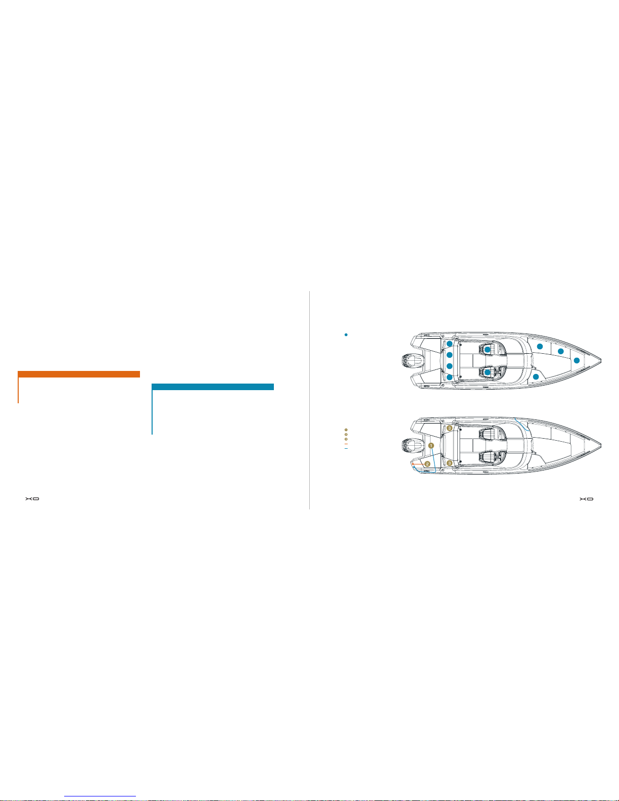
guisher is stored in the console’s left storage compartment as
shown in figure 3. Depending on local legislation, portable fire extin-
guishers must be inspected at regular intervals. Please contact your
local fire authorities for inspection practices in your country.
If you are unsure of local inspection practices, have the portable
fire extinguishers inspected annually. The manufacturing date of
the portable fire extinguisher is indicated on the label glued on the
fire extinguisher. If the fire extinguisher is more than ten years old,
it must undergo pressure vessel pressure testing before it can be
used again. Replacements for old portable fire extinguishers must
have at least the same rating as the originals. Additionally, the boat’s
owner or user is responsible for ensuring there is at least one easily
accessible fire bucket onboard with a rope attached. Make sure that
the fire fighting equipment remains easily accessible also once the
boat is loaded. Show all crew members where the fire fighting equip-
ment is located and how to use it. Keep the bilge clean of fuel and
check regularly for fuel leaks. The smell of petrol is a clear sign of
a fuel leak.
If the boat has a heater, read its safety notice from the instructions
provided by the heater manufacturer.
SPECIAL WARNINGS
Never
• block access to safety equipment, fire extinguisher, fuel valves
or the main power switch of the electrical system.
• block any ventilation openings of the boat, as these are inten-
ded for clearing out fuel fumes.
Additionally, never
• alter the boat’s electrical or fuel system or allow any person
without appropriate qualifications to make any changes in the
boat’s systems.
• fill the fuel tank or handle fuel when the engine is running.
Location of fire extinguisher
(Figure 5)
Fire extinguisher
• smoke or keep an open flame when handling fuel.
• store petrol in areas not intended for its storage. If your boat is
not equipped with a heater, the reserve fuel canister can be sto-
red in the position reserved for the heater’s reservoir.
• leave the boat unattended when the boiler or heater is on.
5.8 ELECTRICAL SYSTEM
The wiring diagram for the boat’s electrical system is included in
appendices 4 and 5. The main power switch is located behind the
steering position on the right side of the boat. However, the auto-
matic bilge pump will always remain on standby as long as the bat-
tery is connected. When the electric circuit is closed, the devices
used for controlling the boat can be operated from the driver's seat.
Navigation lights are switched on from the navigation light switch,
see figure 6. Remember to mount the detachable masthead light
in its place. There is a windscreen wiper on both sides of the boat,
operated from their individual switches. The bilge water level can
be checked by activating the pump manually from its switch, see
figure 5. If you cannot hear the gurgling of water from the aft over
the side, the automatic system has already taken care of draining
the bilge. The electrical system is also accessory-ready: the con-
nectors and wiring required for a radio/CD player and two loudspea-
kers are already in place. The boat can also be equipped with cer-
tain types of fuel-powered heaters. The boat's steering and electri-
cal control arrangement is shown in figure 5.
Instead of traditional fuses, the XO model utilises circuit breakers
which can be reset after overload by pressing down the stud which
has sprang up during overload. The circuit breakers for the electric
circuits are in a separate fuse box within the steering console, see
figure 5. The electrical system includes two auxiliary electrical cir-
cuits with their own circuit breakers (Extra 1: 10 A and Extra 2: 10 A;
positions F13–F14 and F17–F19 in the electrical diagram) for retro-
fitting the boat with optional accessories. The wires for these cir-
cuits are in the control panel. Do not replace the circuit breakers
with ones rated for a higher current nor install components excee-
ding the nominal amperage of the electrical circuit.
Anodes are mounted on the transom. They must be replaced if more
than 50% of the material has dissolved. Please select the anode
material according to the boat’s conditions of use.
CAUTION!
Never ground the hull. All installations must be insulated from the
hull (both from the ground and the plus side).

20 21
Electrical equipment
(Figure 5)
Location of electrical equipment:
Battery box
Main power switch
Bilge pump
Masthead light: white, 360°
Navigation lights: red and green
Control panel
Power socket: 12 V, 10 A max.
Fuse box (see figure 7.)
Windscreen wiper
CONTROL DEVICES
(Figure 6)
Control panel:
Bilge pump activation switch
Signal horn
Windscreen wiper, left
Windscreen wiper, right
Navigation light switch
AUX
Trim tab switch, BB
Trim tab switch, SB

22 23
FUSE BOX
(Figure 7)
F1 Navigation lights
F2 Trim tabs
F3 Signal horn
F4 12 V power outlet
F5 Radio
F6 Automatic fire extinguisher
F7 Windscreen wiper, right
F8 Windscreen wiper, left
F9 Aux
F10 Bilge pump
F11 Extra
F12 Plotter
F13 Reserve
21
SULAKELAATIKKO
(Kuva 6)
F1 Kulkuvalot
F2 Trimmitasot
F3 Äänimerkki
F4 12v virranulosotto
F5 Radio
F6 Automaattisammutin (I/O mallit)
F7 Tuulilasinpyyhin, oikea
F8 Tuulilasinpyyhin, vasen
F9 Aux
F10 Pilssipumppu
F11 Extra
F12 Plotteri
F13 Vara
F13
SPARE
NOTE!
• When retrofitting the boat with accessories, use the circuit Extra
1 or Extra 2. Connect both the power supply wire and the minus
wire to the new device. Never use the boat hull as ground.
• When alighting from the boat for a longer period of time, switch
o the power from the main power switch. Detach the battery
from the system before conducting any electrical work. When dis-
connecting or connecting batteries, be careful not to touch both
poles of the battery or the boat’s aluminium components with a
metal wrench.
• Use only the engine or a battery charger to charge the batte-
ries. Using an excessively high current may cause the battery to
explode. Make sure the battery compartment is suciently ven-
tilated. If ventilation openings are blocked, hydrogen released
during charging may explode.
• Never turn the main switch to the o position when the engine is
running, because this can damage the engine. Altering the boat’s
electrical system or the related diagrams is forbidden; only a qua-
lified boat electrician may conduct maintenance or alteration work
on the boat’s electrical system.
5.9 STEERING PROPERTIES
5.9.1 Driving at high speeds
The maximum rated engine power of the boat is 221 kW (300 hp).
Do not use the boat if it has an engine with a higher power rating
than that indicated on the builder's plate. Use the engine’s electro
hydraulic power trim feature as follows:
• When getting up on plane, use the “bow down” mode.
• Once the boat is on plane and if the waves are small, lift the bow
until the boat starts to porpoise, the propeller loses grip or the
engine reaches the upper limit of its normal adjustment range. Once
this happens, lower the bow slightly until the ride is stable. The log
(speed indicator) ca be used to optimise the trim angle.
• When riding into waves, lower the bow down for a smoother ride.
When driving with a tailwind or driving into extremely high waves,
lift the bow slightly to avoid ploughing.
• Do not drive the boat at high speed when the trim is negative,
i.e. when the bow is low, because the boat can heel and become
unstable to steer. To adjust the trim, also refer to the engine
manufacturer's instructions.
CAUTION!
When driving at high speeds, adjust the trim very carefully; small
changes have a large impact on the boat’s handling. Make sure
that the boat is not excessively trimmed in, as the boat might
make an unexpected turn. Do not drive the boat at high speeds
when trimmed in (bow down). The boat may start banking or its
directional stability when turning may be compromised.
CAUTION!
In speeds over 40 knots, the boat has limited controllability. Rapid
turning motions may cause the boat to run out of control. Slow
down before taking steep turns regardless of the turning direc-
tion. Avoid rapid control movements at high speeds. Do not drive
at full speed on busy lanes or in limited visibility.

24 25
CAUTION!
Waves reduce the boat’s controllability and may cause the boat
to bank. Take this into account by reducing speed when swell
increases.
Learn the rules of marine waterways and follow the provided instruc-
tions as well as the requirements of COLREG (International Regu-
lations for Preventing Collisions at Sea), which must be followed by
all vessels at sea. According to the rules, a proper look-out must be
maintained at all times and right of way must be observed. Navigate
carefully and use new or updated nautical charts. Always adapt your
speed to the current conditions and environment.
Consider the following:
• Swell (also ask whether your passengers find the current speed
comfortable)
• Your own wake wash (largest when getting up on plane, smallest at
hull speed, i.e. at speeds below 10 knots). Observe wake wash rest-
rictions. Reduce speed and wake wash formation as a courtesy as
well as in order to improve the safety of yourself and others.
• Visibility (islands, fog, rain, viewing towards the sun)
• Familiarity with the route (time required for navigation)
• Crowding on the waterways (other trac, noise and wake wash
hitting the shore)
• Space needed for stopping and evasion maneuvers.
5.9.2 EMERGENCY SWITCH
Once the mooring lines have been detached, attach the cord of the
emergency cut-o switch to yourself. For more detailed instruc-
tions, refer to the engine manual. If you fall overboard or stagger in
the boat, it is extremely important that the boat stops, especially if
you are alone in the boat. However, remember to detach the lany-
ard from your wrist before docking or beaching operations to pre-
vent the engine from stopping unintentionally.
DANGER!
A spinning propeller can be lethal to anyone fallen overboard or
swimming close to the boat. Use the emergency switch and shut
down the engine when a swimmer or water skier climbs on board.
5.9.3 Visibility from the steering position
When the weather is calm and beautiful, the boat is easy to ope-
rate. Just remember to arrange the proper look-out as required by
the COLREG regulations. Always make sure that visibility from the
steering position is as good as possible:
• Position the passengers so that they do not limit the driver’s field
of vision. • Do not drive constantly at the planing threshold, as the
raised bow would block the front view.
• Adjust the engine power trim and possible trim tabs to set the boat
position so that the rising bow does not impair visibility.
• Also remember to look behind for ships especially on fairways. Use
appropriate navigation lights after dark and in limited visibility con-
ditions (fog, hard rain).
5.10 CORRECT USE – OTHER RECOMMENDATIONS AND
INSTRUCTIONS
5.10.1 Protection from falling overboard and means of
reboarding
The working decks of the boat are indicated in figure 6. Do not sit,
stand or linger in other parts of the boat when the boat is moving.
Before setting o, make sure the aft railings are locked. The easiest
way to climb back onboard after falling overboard is via the swim-
ming ladder in the aft. The ladder can also be extended from the
water.
5.10.2 Securing loose equipment
Stow anchors and other heavy equipment securely before setting
o. Additionally, light items can be carried o by air gusts, which
should be considered when securing items. When moving, keep all
hatches in the boat closed.
5.10.3 Environmental considerations
Archipelagos and lakes are unique environments and protecting
their environment is a matter of honour for boaters.
Therefore, the following should be avoided:
• Fuel and oil leaks
• Discharge of waste into water or littering the shores
• Releasing washing agents or solvents into waters
• Causing a lot of noise both out on the water and in harbour
• Wake wash formation especially in straits and shallows
Remember to adhere to local environmental laws and regulations.
Learn the international rules for the prevention of marine pollution
(MARPOL) and respect them as much as possible.

26 27
WORKING DECKS AND SWIMMING LADDER
(Figure 7)
Swimming ladder
Working decks
5.10.4 Anchoring, mooring and towing
Always moor your boat carefully even in sheltered docking, as weat-
her conditions may change rapidly. Mooring lines should be equip-
ped with snubbers for damping shocks. Mooring points are indicated
in figure 7. Do not use other parts of the boat for anchoring, mooring
or towing. Use suciently-sized fenders to prevent marring. They
loop in the stem is intended only for use with a trailer or at a slip-
way. It is not designed for perpendicular traction (such as mooring
the boat in a slip). Mooring point strengths are indicated in figure 7.
It is the owner’s or user’s responsibility to make sure that mooring,
towing and anchor lines and anchor chains are suitable for the boat
and that the tensile strength of chains does not exceed 80% of that
of the relevant mooring points. Line wear and loss of strength due
to knots must also be taken into account. When towing, make sure
that the front cleats have a dierent strength than those amidships
and aft. When anchoring in a natural harbour, make sure the depth is
sucient and LOWER THE ANCHOR SUFFICIENTLY FAR FROM THE
SHORE. The anchor will have a reasonable hold when the length of
rope is 4–5 times the water’s depth at the anchor point. Having more
rope out will further improve traction. The anchor will also have sub-
stantially better traction, if the first 3–5 meters of the anchor line is
made of either chain or weighted rope.
CAUTION!
Do not try to stop the boat with your hands only nor place your
hand or foot between the boat and the slip, shore or other boat.
Practice mooring in good conditions using engine power sparingly
but resolutely.
When mooring your boat, consider wind shift, variations in water
level, wake wash and other similar factors. Additional information
is available from insurance companies and other similar sources.
When towing another boat or being towed, use small speeds and
a sufficiently strong, floating towing line. Start towing carefully,
avoiding sharp motions, do not overload the engine. Make sure the
towing line does not get tangled in the propeller. If the other boat has
a displacement hull, do not exceed its hull speed. If you are towing a
small dinghy, adjust the length of the towing line so that the dinghy
rides along the downhill slope of your wake. In straits and heavy
swell, pull the dinghy in closer to the transom, preventing it from
worming. Stow all equipment in the dinghy securely so that it will
not be lost if the dinghy capsizes. When on open sea in a reaso-
nable swell, cover the dinghy to prevent flooding due to spray. When
towing or being towed, fasten the tow line to the mooring points indi-
cated in figure 8. Fasten the towing line so that it can be unfaste-
ned under load.
The yield strength of ropes or chains should not exceed that of the
relevant mooring points.
Always fasten the towing line so that it can be unfastened under
load.

28 29
NOTE!
• The yield strength of ropes or chains should not exceed that of
the relevant mooring points.
• Always fasten the towing line so that it can be unfastened under
load.
• Use small speeds when towing or being towed. If the boat has a
displacement hull, do not exceed its hull speed.
CAUTION!
The towing line is under heavy tension. If the line snaps, the line
end may lash out at fatal speeds. Always use a line with sucient
thickness and do not linger along its path.
For the purposes of towing and anchoring, the yield strength of the
bow cleats is 22 kN.
The forward mooring force for cleats in the bow and amidships is
18.1 kN and, for aft cleats, 15.4 kN.
Cleats used for towing, mooring and anchoring Trailer loop
TOWING AND MOORING
(Figure 8)
5.10.5 Trailer transport
When lifting the XO boat on a trailer, make sure the trailer is suitable
for the boat: there are sucient supports for avoiding concentra-
ted loads and its load-bearing capacity and dimensions are su-
cient to carry the boat and its engine, equipment, battery, boating
accessories and fuel on board. Carefully consult the national road
trac regulations concerning combined transport and the related
driver’s license requirements. Check also that your car has su-
cient towing capacity for pulling the trailer. Remove excess items
and bilge water from the boat before lifting the boat onto the trai-
ler. Adjust the side supports of the trailer so that the keel supports
bear the bulk of the weight and the side supports only provide sup-
port for the boat. Use only the loop in the stem for lifting the boat
onto the trailer; the cleats cannot take the boat’s weight during lif-
ting. Leash the boat securely onto the trailer before transport. Pro-
tect the boat by placing padding between the boat and the straps
where chafing may occur. Check the engine’s manual for additional
instructions concerning trailer transport.
Also remember the boat’s accessories during trailer transport. Make
sure loose items in the boat are stowed securely. Do not cover the
boat with any kind of hood, canopy or boat cover during trailer tran-
sport. At high road speeds, the canopy or cover may become loose
and damage the boat or become a hazard to the boat or other road
users. During trailer transport, the canopy would start flapping due
to air draught and may cause surface damage to the boat. Store
the boat canopy in its locker or detach the canopy completely for
transport. Also, make sure the boat’s door is properly secured for
transport.
NOTE!
The weight of the trailer should rest slightly on the towing bar.
Make sure that the boat is securely lashed to the trailer and that
the boat's weight is distributed evenly against the side supports.
If loose, the boat may roll during transport and hit one of the sup-
ports, potentially damaging the hull.
CAUTION!
A poorly maintained boat trailer, or one with insucient load-car-
rying capacity, may break down during transport, causing a hazard.
Make sure that the trailer's load-bearing capacity is sucient for
the combined weight of the boat, engine, fuel and equipment.
CAUTION!
Do not cover the boat with any kind of hood, canopy or boat cover
during trailer transport. At high road speeds, the canopy or cover
may become loose and damage the boat or become a hazard to
the boat or other road users.
5.10.6 Navigation
The boat must always have a compass and an up-to-date nautical
chart, even if you generally use a GPS chart plotter for navigation.
GPS should only be considered a navigational aid, not the primary
means of navigation. The craft’s commander should have at least
rudimentary navigation skills.

30 31
6 MAINTENANCE, REPAIRS AND
WINTER STORAGE
For information concerning the boat’s maintenance, winter storage,
servicing and repairs, please refer to the closest XO dealer. Major
aluminium or surface treatment repairs should be referred to an aut-
horised XO dealer. If there is a fault in the engine or retrofitted equip-
ment, the primary point of contact is the original equipment supplier.
NOTE!
Make sure that the cleaning, surface treatment and protection
agents are suitable for aluminium and other surface materials
in the boat. Follow the manufacturer’s instructions when using
such chemicals.
7 OPTIONAL ACCESSORIES
7.1 GENERAL
NOTE!
Incorrect retrofits or other alterations may damage the boat’s
hull or compromise safety. Please contact the manufacturer
before making or commissioning any of the following alterations:
adding new hatches or electrical groundings, attaching or instal-
ling equipment or introducing new alloys in the boat's aluminium
components.
NOTE!
If accessories are to be installed in the boat, place non-conduc-
tive washers between the surface-treated aluminium surface and
the surface in contact with the aluminium (either the accessory’s
installation surface or screw head).
7.2 INSTALLING OPTIONAL ACCESSORIES
There is a wide range of electrically powered accessories available
for the XO 250 Open. The required electrical circuits and wires are
already in place. The positions for optional accessories and their
wiring are indicated below. Detailed installation and user instruc-
tions will be provided by the accessory’s manufacturer.
7.2.1 Radio/CD player
The boat comes pre-installed with the wiring required for moun-
ting a car-stereo-type audio system. The slot for the player is loca-
ted under the grip on the left console. The wire assembly includes
two wires for loudspeakers and an Euro connector for the player.
The Euro connector includes the primary power terminal for the
player (connected to the main power switch) as well as a terminal
connected to a circuit bypassing the main power switch (providing
power for the player's memory). Each of the consoles has its own
loudspeaker wire. The slots for embedding the loudspeakers are in
the footwell wall.

32 33
Each boat is identified by a CIN code (Craft Identification Number),
which is a running serial number. The CIN code is marked on the
craft’s hull either on the aft starboard side or on the outer surface
of the transom next to the edge strip. You may enter the CIN code
of your boat in the table below. When contacting the boat builder or
dealer, please state the CIN code and boat type, as this will make it
easier to deliver the correct spare parts.
Type designation: XO 250 Open
CIN code:
Engine make and model:
Engine serial number:
Boat hull material: marine aluminium (AlMg 4.5/5083)
XO 250 Open
Main dimensions:
Total length: 7.52 m
Length on load waterline: 5.70 m
Maximum beam: 2.28 m
Height above waterline: 1.60 m
The height with targa arch above waterline: 2.40 m
(the exact vertical clearance should be checked for each individual
boat)
draught: 0.90 m
Weight specification (outboard model)
Light weight: 1,897 kg
Displacement at full load: 2,745 kg
Maximum total load recommended by the manufacturer: 848 kg
Dry weight (without outboard motor or equipment): 1,440 kg
Total weight of persons: 600 kg (8 persons)
Maximum recommended outboard motor weight: 365 kg
Weight on trailer: 2145 kg
Other cargo or equipment: 75 kg
Volume of fixed fuel tank (both models): 230 l. NOTE: The specified
fill volume of the tank may be limited due to the boat’s trim and load
balance. The tank should always be at least 20 percent full.
CE CATEGORY C
Buoyancy
Maximum recommended number of persons: 8
Bilge pumps
Electrical bilge pump: 28 l/min
Manual bilge pump: 25 l/min @45 strokes/min
Electrical system
Voltage: 12 V DC
Recommended battery capacity: 100 Ah
APPENDIX 1 TECHNICAL SPECIFICATIONS

34 35
Control circuit cables and hoses
Hydraulic steering hoses: 4.50 m (15 ft)
Remote steering device cables: 4.50 m (15 ft)
Manufacturer
XO Boats Oy
Pulttitie 18
FI-00880 Helsinki
Finland
Applicable module: B (EC type-examination)
Notified body
VTT Expert Services Oy
Identity number: 0537
P.O. Box 1001
FI-02044 VTT
Finland
Recreational craft specifications
Boat make and model: XO 250 Open
Design category: C – Inshore
Type-examination certificate no:
Boat type: Open, single-hull inboard/outboard motor boat.
Construction materials: Aluminium alloys, reinforced plastic, PE-HD
Maximum engine power, kW: 224
Length/beam/draught, m: 7.52/2.28/0.90
References to the relevant harmonised standards and provisions
are provided on the following page.
I hereby declare that the recreational craft specified above satis-
fies the relevant safety requirements according to the specifica-
tion provided on the following page and the EC type inspection cer-
tificate provided.
XO Boats Oy
Henrik Thelen, CEO
Date: 15 Jan 2015
1
APPENDIX 2 XO 250 OPEN / GENERAL ARRANGEMENT
Masthead light: white, full coverage, power: 10 W
a) Battery box, b) fuse box and c) main power switch
Navigation lights: 112.5° red and 112.5° green, power: 10 W
Fuel tank filler hose
Powder extinguisher: 2 kg, rating: 13A/89BC
Fuel tank
The general arrangement drawings of the boat are not in
scale. Due to continuous product development, the manu-
facturer assumes no liability for deviations.
Drain plug
Bilge pump 7a) Automatic bilge pump
Fuel tank service hatch
Fuel tank breather
Cockpit drain well
Fuel tank inlet
Fuel filter/water separator
Cockpit drain valves
Life raft (optional)

36 37
General requirements, outboard motor model
Basic specifications: EN ISO 8666:2002
2.1 Hull identification marking: ISO 10087:1996 / A1:2000
2.2 Builder’s plate: RCD Annex I, 2.2
2.5 Owner’s manual: EN ISO 10240:2004
Arrangement and equipment
2.3 Protection from falling overboard and means of reboarding:
EN ISO 15085:2003
3.7 Life raft stowage: RSG Guidelines
3.8 Emergency exit: n/a
3.9 Anchoring, mooring and towing: EN ISO 15084:2003
5.7 Navigation lights: 1972 COLREG
5.8 Emission prevention: n/a
Installations
5.1 Engines and engine spaces: n/a
5.2 Fuel system: EN ISO 10088:2001, EN ISO 11105:1997
5.3 Electrical system: EN ISO 10133:2000
5.4 Steering system: EN ISO 10592:1994/A1:2000
5.5 Gas equipment: n/a
5.6 Fire safety: EN ISO 9094-1:2003
Dimensions
3.1 Structure: ISO 12215-3:2002, ISO 12215-5:2008,
ISO 12215-6:2008
Hydrostatics
3.2 Stability and freeboard: EN ISO 12217:2002
3.3 Buoyancy and flotation: EN ISO 12217:2002
3.6 Maximum allowed load: EN ISO 14946:2001/AC 2005
3.4 Openings in the hull, deck and superstructure:
EN ISO 9093-1:1997, EN ISO 12216:2002
3.5 Flooding: EN ISO 11812:2001, EN ISO 15083:2003, ISO 8849
Steering properties
3.5 Flooding: EN ISO 11812:2001, EN ISO 15083:2003, ISO 8849
4 Steering properties: EN ISO 11592:2001, EN ISO 8665:2006
2.4 Visibility from steering position:
RSG Guidelines, EN ISO 11591:2000
Engine identification; Engine CE-marked
Noise emission level; Engine CE-marked
APPENDIX 3 GENERAL REQUIREMENTS APPENDIX 4 ELECTRICAL WIRING DIAGRAM
38
LIITE 5 SÄHKÖKYTKENTÄKAAVIO / PERÄMOOTTORIMALLI
Projectrev.
Sheetrev.
Drawingby
Date
Modifiedby
Description
A
B
C
D
E
F
1
2345678
Dateofmodification
Sheet
Loc
HL
/
ProjectID
Boat
Boatmodel
Productcode
Copyrightby
Subproductcode
Title
1
2345678
A
B
C
D
E
F
5
24
XO
1.6.2010
RN
8
F
1
DIAGRAM
1
2
M_F.1
25A
MAIN
1
1
2
M_F.2
25A
MAIN
1
1
2
M_F.3
10A
BILGEP.AUTO
1
1
2
M_F.4
10A
MEMORY
1
1
2
M_F.5
7A
CTRL
1
M_F:1
M_F:2
M_F:3
M_F:4
M_F:5
I
01
2
4487
M_S1
275A/1250A
MAINSWITCH
G1
BATTERY
1/1
G1a
M_S1a
/4.E1
BILGE_P_AUTO
/2.B6
MEMORY
/2.A1
INPUT+
/3.A2
INPUT+
M_S1c
M_S1b
/20
B.1
/20
G1b
1/1
70/10
G1c
B1
/2.F1
INPUT
A6
ACPS
/20
B.1
1/6
X.11
1/6
X11
2/6
X11
B1
2/6
X.11
/20
B.1
A7
FUELTANK
B1
5/6
X.11
5/6
X11
A8
FUELGAUGE
6/6
X.11
6/6
X11
+
/1.F3
B2
/1.E3
B2
M
M7
1/1
70/8
B2a
1/1
70/8
B2b
1/1
70/10
G1d
1/1
70/10
M_S1e
A10
FUELGAUGE
/2.F8
INPUT
/2.E4
INPUT
2.5
RED
2.5
RED
2.5
RED
6
RED
6
RED
4
BLACK
4
BLACK
70
RED
6
RED
6
RED
2.5
RED
1.5
BLUE/RED
DIRECT+
DIRECT+
DIRECT+
INPUT+
INPUT+
INPUT
INPUT
BATTERY+
INPUT+
INPUT+
BILGE_P_AUTO
MEMORY
1.5
LIGHTRED
1.5
BLACK
INPUT
1.5
BLACK
INPUT
CONTROL
1
BLACK
INPUT
1
RED
FUEL_G
1
BLACK
INPUT
1
RED
FUEL_G
70
BLACK
INPUT
70
RED
INPUT+
1
BLACK
1
RED
FUEL_G
1.5
LIGHTRED
CONTROL
1
BLACK
INPUT
1
BLACK
OB
SYSTEM
INBOARDENG.
SYSTEM
OUTBOARDENG.

38 39
39
A3
Projectrev.
Sheetrev.
Drawingby
Date
Modifiedby
Description
A
B
C
D
E
F
1
2345678
Dateofmodification
Sheet
Loc
HL
/
ProjectID
Boat
Boatmodel
Productcode
Copyrightby
Subproductcode
Title
1
2345678
A
B
C
D
E
F
5
24
XO
31.5.2010
RN
8
F
2
DIAGRAM
1
2
F.1
10A
NAV./ANCH.LT
1
2
1
2
F.2
25A
TRIM
1
2
1
2
F.3
10A
HORN
1
2
1
2
F.4
10A
OUTLET
1
2
1
2
F.5
10A
RADIO
1
2
4/8
X.2a
5/8
X.2a
6/8
X.2a
7/8
X.2a
8/8
X.2a
1/8
X.2a
/1.E3
INPUT+
1/8
X2a
ANCH.LT
H1
NAV.LT
H2
NAV.LT
H3
/3.A1
INPUT+
HORN
H4
+
A.2
12VDC
+
A2
A2
4/8
X2a
5/8
X2a
6/8
X2a
7/8
X2a
1/8
X.5a
1/8
X5a
2/8
X.5a
1/8
X.6a
4/8
X.6a
5/8
X.6a
1/8
X6a
4/8
X6a
5/8
X6a
8/8
X2a
2/8
X5a
/20
B.1
B1
/20
3/8
X.5a
3/8
X5a
/20
B.1
B1
/20
B.1
B1
4/8
X25a
8/8
X25a
6/8
X25a
/1.E5
MEMORY
LS.1
LS.2
LS1LS1
LS2LS2
1/8
X25b
5/8
X25b
4/8
X25b
8/8
X25b
4/8
X5a
5/8
X5a
4/8
X.5a
5/8
X.5a
6/8
X.6a
6/8
X6a
2/8
X.6a
3/8
X.6a
2/8
X6a
3/8
X6a
6/8
X.5a
6/8
X5a
/3.F1
INPUT
/1.F8
INPUT
COMPASSL.
H5
A1
TRIM
/20
4102
B.1
B1
6/8
X6c
6/8
X.6c
A4
FIREIND.
A5
FIREEXT.
1
2
F.6
10A
FIREEXT.
1
2
3/8
X2a
3/8
X.2a
3
4
2335501
S1.1
3
4
2335501
S1.2
I
0
II
M22WRLK3W
S1
WITH
2335500
3
4
2335501
S6.1
1
2
P600G
D1
6A
I
0
M22DS
S6
/1.F7
INPUT
/2.D6
INPUT
/2.F2
INPUT
/3.F2
INPUT
/1.F8
INPUT
6
RED
6
RED
INPUT+
1
RED
NAV/ANC_L_IN NAV/ANC_L_IN
1
RED
NAV/ANC_L_IN
1
RED
6
RED
TRIM
1.5
BROWN
HORN_IN
1.5
GREEN/BLACK
OUTLET
1.5
RED
RADIO
4
RED
TRIM
4
RED
TRIM
1.5
BROWN
HORN_IN
1.5
BROWN
HORN_IN
1.5
GREEN/BLACK
OUTLET
1.5
BLACK
INPUT
2.5
BLACK
INPUT
1.5
BROWN
HORN_OUT
1.5
RED
RADIO
1.5
RED
RADIO
1.5
BLUE/RED
MEMORY
1.5
PURPLE
SPKR_STB+
1.5
PURPLE/BLACK
SPKR_STB
1.5
PURPLE
SPKR_STB+
1.5
PURPLE/BLACK
SPKR_STB
1.5
GREY/GREEN
SPKR_PORT+
1.5
GREEN/BLACK
SPKR_PORT
1.5
BLACK
INPUT
ANC_L_OUT
1
RED
1
RED
NAV/COMP_L_OUT
1
BLACK
INPUT
1
BLACK
1
RED
1
RED
1
BLACK
1
RED
NAV/COMP_L_OUT
NAV/COMP_L_OUT
INPUT
1.5
BROWN
HORN_OUT
1.5
BLUE/RED
1
RED
NAV/COMP_L_OUT
4
BLACK
INPUT
4
BLACK
INPUT
1
BLACK
INPUT
1.5
BLACK
1
BLACK
FIRE_EXT
1
RED
1
RED
FIRE_IND
1
RED
FIRE_IND
1
RED
ANC_L_OUT
1
BLACK
1.5
BLACK
1
BLACK
40
Projectrev.
Sheetrev.
Drawingby
Date
Modifiedby
Description
A
B
C
D
E
F
1
2345678
Dateofmodification
Sheet
Loc
HL
/
ProjectID
Boat
Boatmodel
Productcode
Copyrightby
Subproductcode
Title
1
2345678
A
B
C
D
E
F
5
24
XO
31.5.2010
RN
8
F
3
DIAGRAM
1
2
F.7
7A
WIPERSTB
1
2
1
2
F.8
7A
WIPERPORT
1
2
1
2
F.9
10A
AUX
1
2
1/8
X.2b
2/8
X.2b
3/8
X.2b
2/8
X.2a
/1.E4
INPUT+
2/8
X2a
/4.A1
INPUT+
/2.A8
INPUT+
1/8
X.6b
1/8
X6b
1/8
X2b
M
WIPERPORT
M2
2/8
X6b
3/8
4/8
5/8
X6b
6/8
X6b
7/8
8/8
2/8
X2b
5/8
X.6b
1/4
X.9
2/4
3/4
4/4
1/4
X9
2/4
3/4
4/4
M
WIPERSTB
M1
8/8
4/8
3/8
2/8
X.6b
7/8
6/8
X.6b
1/8
X5b
2/8
3/8
4/8
1/8
X.5b
2/8
3/8
4/8
3/8
X2b
/2.F8
INPUT
/4.F1
INPUT
/20
B.1
B1
3
4
2335501
S4.1
3
4
2335501
S4.2
I
0
II
M22WRLK3W
S4
WITH
2335500
3
4
2335501
S3.1
3
4
2335501
S3.2
I
0
II
M22WRLK3W
S3
WITH
2335500
I
0
M22WRLKW
S2
/2.F4
INPUT
1/8
X.6c
1/8
X6c
3
4
2335501
S2.1
1/3
X.4
2/3
X.4
1/3
X4
/20
B.1
B1
+
CABINLT
H29
+
CABINLT
H31
1/2
X.3
2/2
X.3
1/2
X3
2/2
X3
+
CABINLT
H33
+
CABINLT
H32
2/3
X4
6
RED
INPUT+
6
RED
1.5
WHITE/BLUE
WIPER_SB_IN/C
1.5
WHITE/BROWN
WIPER_BB_IN/C
1.5
PURPLE
AUX/CAB_L_IN
1.5
WHITE/BLUE
WIPER_SB_IN/C
1.5
WHITE/BROWN
WIPER_BB_IN/C
1.5
WHITE/BLUE
1.5
WHITE/BROWN
WIPER_SB_IN/C
WIPER_BB_IN/C
1.5
WHITE/RED
1.5
PURPLE
1.5
WHITE/BROWN
1.5
WHITE/GREEN
1.5
LIGHTRED
1.5
WHITE/BLUE
1.5
WHITE/RED
1.5
WHITE/BROWN
1.5
BLACK
1.5
WHITE/GREEN
1.5
WHITE/BLUE
1.5
BLACK
1.5
WHITE/RED
1.5
PURPLE
1.5
WHITE/BROWN
1.5
BLACK
1.5
WHITE/RED
1.5
PURPLE
1.5
WHITE/BROWN
1.5
BLACK
WIPER_BB_I
WIPER_BB_IN/C
WIPER_BB_II
WIPER_SB_II
WIPER_SB_I
WIPER_SB_IN/C
1.5
LIGHTRED
WIPER_SB_II
WIPER_SB_I
WIPER_SB_IN/C
WIPER_BB_II
WIPER_BB_I
WIPER_BB_IN/C
1.5
PURPLE
1.5
PURPLE
1.5
PURPLE
AUX/CAB_L_IN
1.5
PURPLE
1.5
WHITE/YELLOW
1.5
BLACK
1.5
WHITE/YELLOW
1.5
BLACK
1.5
WHITE/YELLOW
1.5
BLACK
1.5
BLACK
1.5
WHITE/YELLOW
1.5
WHITE/YELLOW
CABIN_LT_OUT
1.5
BLACK
INPUT
Table of contents
Other Xo Boat manuals