Cutwater C-32 User manual

C-32 Owner’s Manual

2
Table Of Contents ........................................................................................................ 2
Congratulations ........................................................................................................... 3
Safety .......................................................................................................................... 3
Safety Sticker Location ................................................................................................. 4
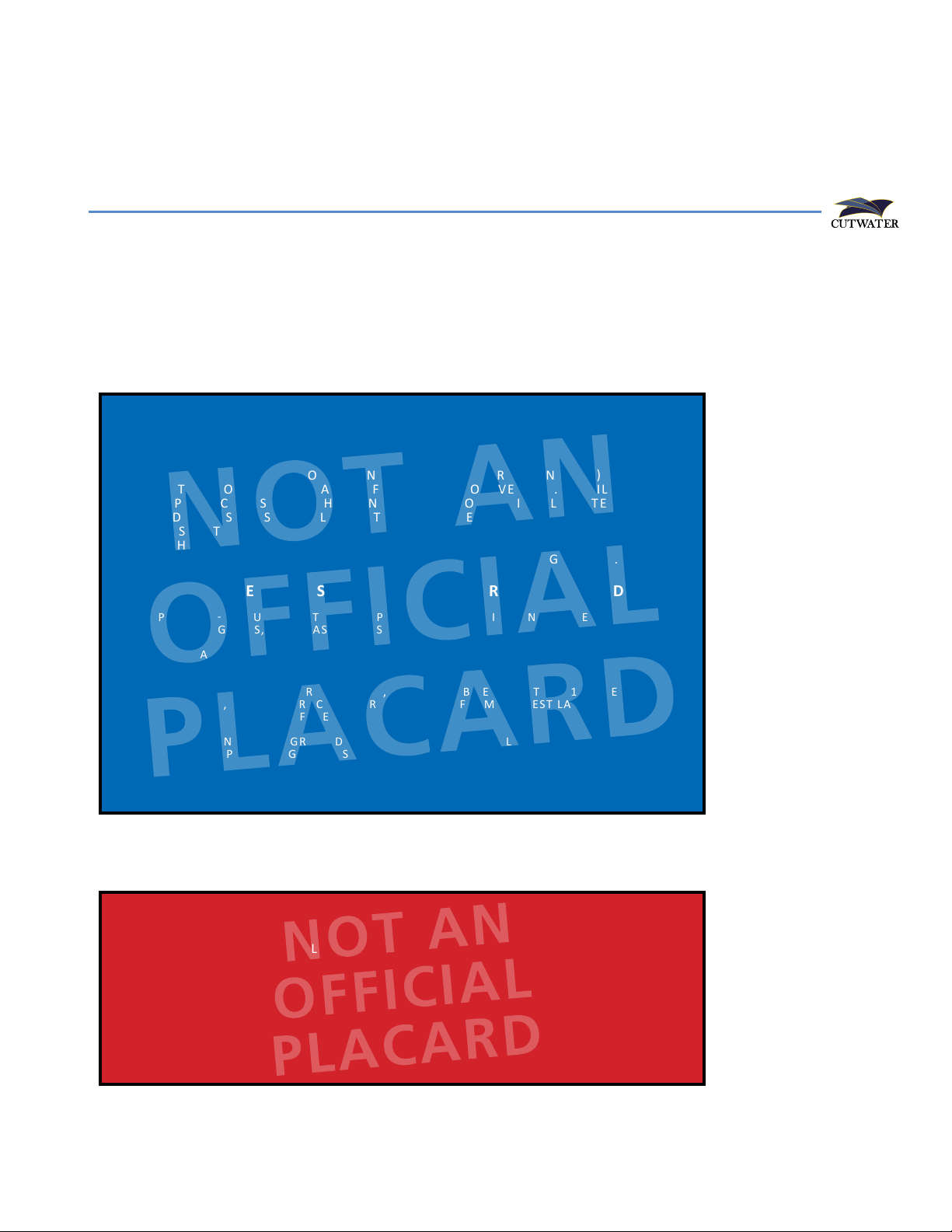
Garbage Disposal & Oil Overboard Placards .................................................................. 5
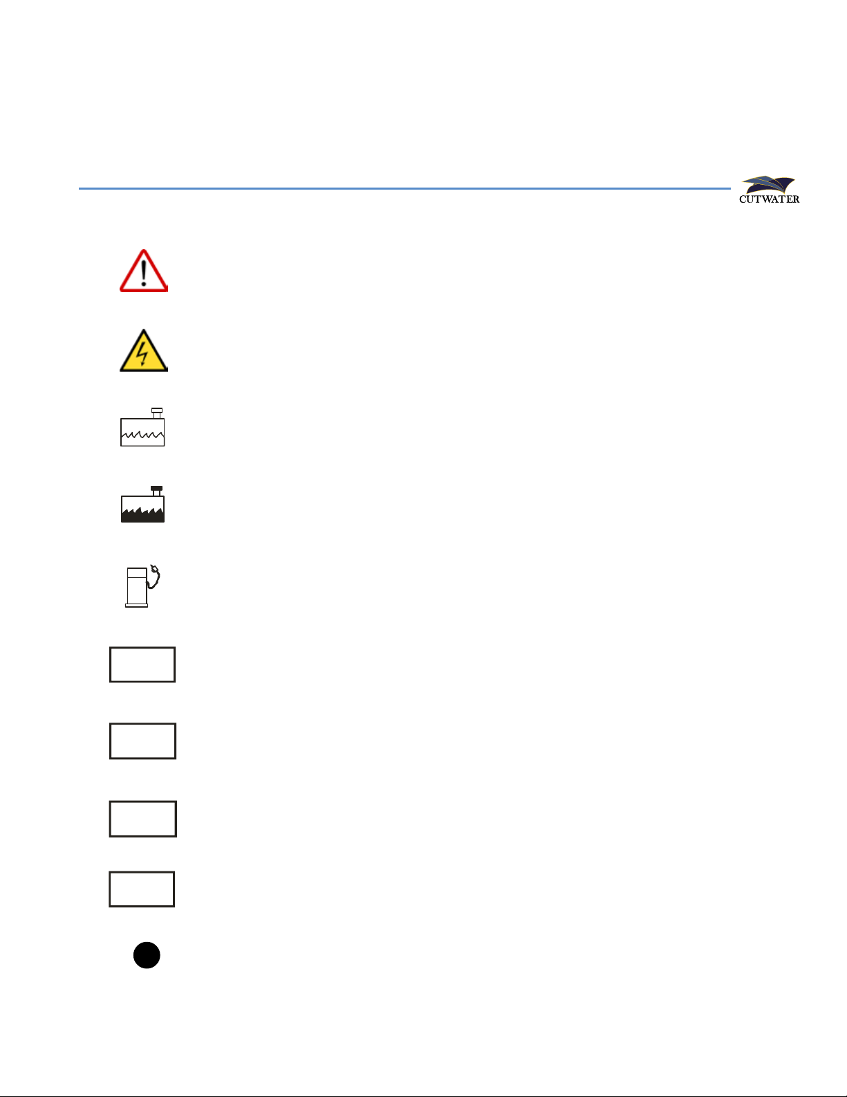
Symbol Glossary ........................................................................................................... 6
Specifications (Subject To Change Without Notice) .................................................................. 7
Sanitation of Potable Water System .............................................................................. 8
Equipment Location ..................................................................................................... 9
Starboard Fittings .................................................................................................. 9
Port Fittings ........................................................................................................... 10
Main Cabin Top Deck Components ....................................................................... 11
Stern Components ................................................................................................. 12
Fuse Location & Values .......................................................................................... 13
Main Cabin And Cockpit Lights ............................................................................. 15
Battery Compartment ............................................................................................ 16
Power Distribution Center ..................................................................................... 17
Systems Control Center.......................................................................................... 18
AC Distribution Panel, Switch & DC Volt Meter ...................................................... 19
Inverter ................................................................................................................. 20
Shore Power Layout ............................................................................................... 21
Solar Panel ............................................................................................................ 22
Generator ............................................................................................................. 23
Fuel System - Engine and Generator ...................................................................... 24
Webasto Furnace .................................................................................................. 25
Air Conditioning System ........................................................................................ 26
Sea Strainer System ............................................................................................... 27
Fresh Water Plumbing System ................................................................................ 28
Shower Sump ........................................................................................................ 29
Bilge Pump System ................................................................................................ 30
Waste System with Macerator Pump ..................................................................... 31
Mast Set Up And Take Down ................................................................................. 32
Cutwater 32 Wiring Schematic (Acc. 1) ................................................................. 33
Cutwater 32 Wiring Schematic (Acc. 2) ................................................................. 34
Cutwater 32 Wiring Schematic (Acc. 3) ................................................................. 35
Cutwater 32 Wiring Schematic (Lighting) .............................................................. 36
Cutwater 32 Wiring Schematic (P.D.P.) ................................................................... 37
Working Deck .............................................................................................................. 38
Care And Maintenance ................................................................................................ 39
Example Of A Preparation For The Road Checklist .................................................. 39
Example Of A Spring Pre-Launch Checklist ............................................................. 40
Example Of Winter Storage Checklist .................................................................... 41
Contacts ...................................................................................................................... 42
Notes ........................................................................................................................... 43
TABLE OF CONTENTS

3
CONGRATULATIONS
The Cutwater family has a passion for boating. We are committed to continuous
process improvement in all areas that affect our customer’s satisfaction with our
products and providing great customer service.
SAFETY
Safety is always a concern at Cutwater. Please read all manuals to ensure that equip-
ment is used in a safe manner. We highly recommend attendance in a Coast Guard
approved boating safety course. Such courses are available from the Coast Guard
directly or from boating organizations. Owners should have annual inspections to
ensure that all safety equipment is current.
MAXIMUM HORSEPOWER
DESIGNED FOR TWIN OUTBOARDS
MAX 300 HORSEPOWER EACH
Operating, servicing and maintaining
a recreational marine vessel can expose
you to chemicals including engine exhaust,
carbon monoxide, phthalates, and lead,
which are known to the State of California
to cause cancer and birth defects or other
reproductive harm. To minimize exposure,
avoid breathing exhaust, service your vessel
in a well-ventilated area and wear gloves or
wash your hands frequently when servicing
this vessel. For more information go to
www.P65warnings.ca.gov/marine.
Prop 65 Boat Owner’s
Manual Image
Notes on use of the above:
27 CCR § 25607.18
§ 25607.18. Recreational Vessel Exposure Warnings -
Method of Transmission. [Operative August 30, 2018]
(a) A warning for exposures that occur during the operation
or maintenance of a recreational vessel as defined in California
Harbor and Navigation Code Section 651(t) meets the
requirements of this subarticle if it complies with the content
requirements in Section 25607.19 and is provided as follows:
(1) The warning is printed in the owner's manual for the
specific recreational vessel, in no smaller than 12-point type
enclosed in a box printed or affixed to the inside or outside
of the front or back cover of the manual or on the first page
of the text, and;
(2) The warning is provided on a hang tag readily visible from
the helm of the vessel printed in no smaller than 12-point type.

4
SAFETY STICKER LOCATION

5
Required by the USCG in a language all passengers understand. These are installed
at the factory. If damaged or missing after use they should be replaced.
Text should cover approximately the following:
GARBAGE DISPOSAL
OIL OVERBOARD
GARBAGE DISPOSAL & OIL OVERBOARD PLACARDS
DISPOSAL OF ALL GARBAGE PROHIBITED
EXCEPT OTHERWISE SPECIFIED
THE ACT TO PREVENT POLLUTION FROM SHIPS (MARPOL ANNEX V) PLACES
LIMITATIONS ON THE DISCHARGE OF GARBAGE FROM VESSELS. IT IS ILLEGAL TO
DUMP PLASTIC TRASH ANYWHERE IN THE OCEAN OR NAVIGABLE WATERS OF THE
UNITED STATES. IT IS ALSO ILLEGAL TO DISCHARGE GARBAGE IN THE NAVIGABLE
WATERS OF THE UNITED STATES, INCLUDING THE GREAT LAKES. THE DISCHARGE
OF OTHER TYPES OF GARBAGE IS PERMITTED OUTSIDE OF SPECIFIC DISTANCES
OFFSHORE AS DETERMINED BY THE NATURE OF THAT GARBAGE.
VIOLATION MAY RESULT IN HEAVY PENALTIES
TYPE OF WASTE
PLASTICS - INCLUDES SYNTHETIC ROPES,
FISHING NETS, AND PLASTIC BAGS
FLOATING DUNNAGE, LINING AND
PACKING MATERIALS
FOOD WASTE, PAPER, RAGS, GLASS,
METAL, BOTTLES, CROCKERY, OR
SIMILAR REFUSE
COMMINUTED OR GROUND FOOD
WASTE, PAPER, RAGS, GLASS, ETC.
DISCHARGE PERMITTED
PROHIBITED IN ALL AREAS
PROHIBITED LESS THAN 25 MILES
FROM NEAREST LAND
PROHIBITED LESS THAN 12 MILES
FROM NEAREST LAND
PROHIBITED LESS THAN 3 MILES
FROM NEAREST LAND
DISCHARGE OF OIL PROHIBITED
THE FEDERAL WATER POLLUTION CONTROL ACT PROHIBITS THE DISCHARGE
OF OIL OR OILY WASTE INTO OR UPON THE NAVIGABLE WATERS OF THE
UNITED STATES, OR THE WATERS OF THE CONTIGUOUS ZONE, OR WHICH MAY
AFFECT NATURAL RESOURCES BELONGING TO, APPERTAINING TO, OR UNDER
THE EXCLUSIVE MANAGEMENT AUTHORITY OF THE UNITED STATES. IF SUCH
DISCHARGE CAUSES A FILM OR DISCOLORATION OF THE SURFACE OF THE WATER
OR CAUSES A SLUDGE OR EMULSION BENEATH THE SURFACE OF THE WATER,
VIOLATORS ARE SUBJECT TO SUBSTANTIAL CIVIL PENALTIES AND/OR CRIMINAL
SANCTIONS INCLUDING FINES AND IMPRISONMENT.

6
SYMBOL GLOSSARY
STD
OPT
Attention! – Important Operating or Maintenance Instructions
Attention! – Electrical Shock Hazard
Fresh Water
Black Water
Fuel
Standard Equipment
Optional Equipment
Northwest Edition
LE
NW
Luxury Edition
Hints

7
SPECIFICATIONS
(Subject to Change Without Notice)
C-32 SEDAN
LOA (motors down) ....................................................................... 37’ 8” 11.5 m
LOA (motors up) ............................................................................ 39’ 10” 12.1 m
Beam............................................................................................. 10’ 3.05 m
Draft (motors up)........................................................................... 26” .66 m
Draft (motors down) ...................................................................... 33” .84 m
Weight (dry)................................................................................... 10,000 lbs 4,536 kg
Bridge clearance (mast/down) ........................................................ 9’ 9” 3m
Height on trailer............................................................................. 13’ 6” 4.1 m
Fuel capacity.................................................................................. 300 U.S. Gal 1,135.6 L
Water capacity............................................................................... 80 U.S. Gal 302.8 L
Holding tank capacity .................................................................... 40 U.S. Gal 151.4 L
C-32 CB
LOA (motors down) ....................................................................... 37’ 8” 11.5 m
LOA (motors up) ............................................................................ 39’ 10” 12.1 m
Beam............................................................................................. 10’ 3.05 m
Draft (motors up)........................................................................... 26” .66 m
Draft (motors down) ...................................................................... 33” .84 m
Weight (dry)................................................................................... 10,780 lbs 4,890 kg
Bridge clearance (mast/down) ........................................................ 9’ 9” 3m
Height on trailer............................................................................. 13’ 6” 4.1 m
Fuel capacity.................................................................................. 300 U.S. Gal 1,135.6 L
Water capacity............................................................................... 80 U.S. Gal 302.8 L
Holding tank capacity .................................................................... 40 U.S. Gal 151.4 L

8
SUGGESTED METHOD OF DISINFECTION
Perform the following steps in the order indicated at least once a year:
a. Flush entire system thoroughly by allowing potable water to flow through it.
b. Drain system completely.
c. Fill entire system with a chlorine solution having a strength of at least 100 parts
per million, and allow to stand for one (1) hour. Shorter periods will require
greater concentrations of chlorine solution. See Table Below
d. Drain chlorine solution from entire system.
e. Flush entire system thoroughly with potable water.
f. Fill system with potable water.
Table I shows how much disinfecting agent is required to make up various quantities
of 100 parts per million chlorine solution.
CHLORINE CONCENTRATIONS
Amount of chlorine compound required for 100 ppm solution
NOTE: This table contains information taken from the Handbook on Sanitation of
Vessel Water Points, Public Health Service Publication No. 274 - Reprinted June 1963.
SANITATION OF POTABLE WATER SYSTEM

9
3 8
1 2 4 5 6 7 9 10 11
Keep all vents, drains and exhausts clear of any obstructions
to ensure proper performance of each system.
STD
➌
➎
➊ Fuel Fills & Vents
➋ Bilge Pump Outlets
➌ Generator Air Blower
➍ Swim Ladder
➎ Stern Thruster
➏ Waste Pumpout
➐ Waste Vent
➑ Macerator
➒ Head Sink Drain
➓Bow Thruster
Docking Lights
11
EQUIPMENT LOCATION
STARBOARD FITTINGS
➊
➊
➋
11
➓
➑➒
➏
➐
➍

10
1 2 3 4 5 6 7 8 12 14 16
9 10 13 15
Keep all vents, drains and exhausts clear of any obstructions
to ensure proper performance of each system.
➌
➎
11
➊ Docking Lights
➋ Anchor Locker Drain
➌ Bow Thruster
➍ Shower Sump
➎ Air Conditioner Drains
➏ Cabin Sink Drain
➐ Freshwater Vent
➑ Webasto Air Intake
➒ Webasto Exhaust
➓ Diesel Fill
Freshwater Fill
Generator Blower
Fish Locker Drain
Generator Exhaust
Bilge Drain
11
12
12
13
13
14
15
14 15
STD
PORT FITTINGS
➊
➋
➓
➑
➒
➏➐
➍

11
MAIN CABIN TOP DECK COMPONENTS
STD
1 2 3 6 7
4 5 8
➊ Searchlight
➋ Horn
➌ Digital TV Antennae
(satellite ready - not included)
➍ Radar
➎ XM-Weather Antennae
➏ Anchor Light
➐ Port Navigation Light
➑ Solar Panel
Sedan
Command Bridge
➊
➊
➋
➋
➌
➌
➎
➎
➏
➏
➍
➍
➐
➐
➑
➑

12
STERN COMPONENTS
STD
1 2 3 4 5 6 7
➊ Courtesy Lights
➋ Cockpit Drains
➌ Underwater Lights
➍ Fenders
➎ Stern Thruster
➏ Swim Platform Retractable Ladder
➐ Trim Tabs
➑ Drain Plug
➊ ➊
➋
➎
➌ ➌
➐ ➐
➍ ➍ ➏
➑

13
FUSE LOCATION & VALUES
STD
The dash fuse blocks are located behind the hinged mirror located inside of the bathroom.
Fuses are automotive blade type and all values are shown in amps.
Dash Fuse Block #1 Dash Fuse Block #2
Last Update:6/12/19
Volt Meter
(Battery#2)
CW-30/32
Fuse Block Layouts
Thruster Battery
Seat Sensor +
Engine Battery
LPG Controller
Hatch Switch
Outboard Engine
Pod Pump
FWDBilgePump
AFTBilgePump
Volt Meter
(Battery #3)
COMonitor(AFT)
CO Monitor (FWD)
Bilge Alarm
Battery Panel LT
PDP
12VOutlet(QuarterBerth)
Downrigger(Star)
Downrigger(Port)
Refrigerator(Aft)
InboardPanel(4Switch)
Refrigerator
AutopilotPump
FreshWaterPump
Cockpit Pump Panel
CabinLights
Misc. Lights
Spotlight
Light Switch (V-berth)
Dash #1
TV#1
InboardPanel(4Switch)
Head
OutboardPanel (8Switch)
12V Outlet (Dinette)
OutboardPanel(8Switch)
Radar(Option)
Webasto Heater
TV#2
TV Antenna
Radar(Option)
Network(Option)
Transducer(Option)
Navigation (Optional)

14
Thruster Battery
Engine Battery
Last Update:6/12/19
Volt Meter
(Battery#2)
CW-30/32
Fuse Block Layouts
Thruster Battery
Seat Sensor +
Engine Battery
LPG Controller
Hatch Switch
Outboard Engine
Pod Pump
FWDBilgePump
AFTBilgePump
Volt Meter
(Battery #3)
COMonitor(AFT)
CO Monitor (FWD)
Bilge Alarm
Battery Panel LT
PDP
12VOutlet(QuarterBerth)
Downrigger(Star)
Downrigger(Port)
Refrigerator(Aft)
InboardPanel(4Switch)
Refrigerator
AutopilotPump
FreshWaterPump
Cockpit Pump Panel
CabinLights
Misc. Lights
Spotlight
Light Switch (V-berth)
Dash #1
TV#1
InboardPanel(4Switch)
Head
OutboardPanel (8Switch)
12V Outlet (Dinette)
OutboardPanel(8Switch)
Radar(Option)
Webasto Heater
TV#2
TV Antenna
Radar(Option)
Network(Option)
Transducer(Option)
FUSE LOCATIONS AND VALUES CONTINUED
STD
These four blocks and fuses are located in the Quarter Berth aft storage area and under
the Helm on the Bridge.
The bilge pumps operate automatically even when all switches and breakers are in the OFF position.
They will detect for water for 1 second once every 2 and a half minutes and run if needed.
However, the FORWARD BILGE PUMP and AFT BILGE PUMP will run continuously once their helm
switches are placed in the on position. Monitor the outflow accordingly. Do not run when dry.
Thruster Battery and Engine Battery fuse blocks are energized even when the battery switch is off.
Optional: Located under Helm on Bridge
PDP

15
MAIN CABIN AND COCKPIT LIGHTS
STD
Switch for ➑
Switch for ➏
Switch for ➊& ➋& ➒
Switch on fixture for ➌
Switch on fixture for ➎➎ ➎
➍
➍
➍
➍
➍
➊
➊
➊
➊
➊
➊
➊➊
➒➒
Switch for ➌
Switch for ➍& ➐
➋➋
➌
➌➌➌
➌
➌➌
➌
➌
➏
➏
➏
➐
➑
➑

16
BATTERY COMPARTMENT
STD
House Batteries, Engine Battery, Thruster Battery, Inverter/Charger
Inverter Fuse (150 AMP), Inverter/Charger Cutoff Switch.
Inverter / Charger
322
1 1
1 1
Batteries
1= House
2= Engine
3= Thruster

17
POWER DISTRIBUTION CENTER
The parallel switch should always remain in the off position.
While in the on position, the house and engine batteries will be
combined as one for emergency start only.
STD
Located in the upper cockpit hatch on the starboard side of the
main cabin door. House, Engine, Thruster, and Crossover switches.
O
OFF
EMERG
PARALLEL
O
OFF
EMERG
PARALLEL
O
OFF
BOW
THRUSTER
O
OFF
STERN
THRUSTER
O
OFF
HOUSE
+ -
O
OFF
HOUSE
+ -
—
ON
HOUSE
+ -
O
OFF
ENGINE
STBD
O
OFF
ENGINE
PORT
ON
OFF
VOLTAGE SENSOR RELAY VOLTAGE SENSOR RELAY
VOLTAGE SENSOR RELAY
Bow Thruster 200 Amp ANL Bus Fuse
Stern Thruster 200 Amp ANL Bus Fuse
50 Amp Bridge Breaker (optional)
50 Amp Quarter Berth Breaker
510 Amp Dash

18
Located in midberth
SYSTEMS CONTROL CENTER
STD
Water Pump
gauge/switch
ELCI
Battery Voltage
Meter
SolarRear Heat Control
Inverter/Battery
Charger
SHORE
12 VOLTS DC
LINE VOLTAGE
DC V
RESET TEST
WARNING!
TEST BEFORE
EACH USE
POWER
ON
30
OFF
FAULT
G
R
O
U
N
D
F
A
U
L
T
S
E
N
S
I
N
G
M
O
D
U
L
E
MeTer
Charge
MT-1
1 2
12.9
max
NEXT
ON/STATUS
SET
Error
HOUSE
ENGINE
THRUSTER
ON
KISAE
SELECT
Status
Charger
Inveter
Fault
DV Volts
KiloWatts
Display
Abso Inverter Charger
POWER
Water Pump
gauge/switch ELCI
Battery Voltage
Meter
SolarBlowersGenerator
Inverter/Battery
ChargerAir Conditioner
12 VOLTS DC
LINE VOLTAGE
DC V
MeTer
Charge
MT-1
1 2
12.9
max
NEXT SET
Error
SHORE 1
RESET TEST
WARNING!
TEST BEFORE
EACH USE
POWER FAULT
G
R
O
U
N
D
F
A
U
L
T
S
E
N
S
I
N
G
M
O
D
U
L
E
ON
30
OFF
SHORE 2
RESET TEST
WARNING!
TEST BEFORE
EACH USE
POWER FAULT
G
R
O
U
N
D
F
A
U
L
T
S
E
N
S
I
N
G
M
O
D
U
L
E
ON
30
OFF
HOUSE
ENGINE
THRUSTER
BLOWERS
PORT
STBD
ON
KISAE
SELECT
Status
Charger
Inveter
Fault
DV Volts
KiloWatts
Display
Abso Inverter Charger
POWER
FCF
START
SPEED
OIL PRESSURE
ENGINE TEMP EXHAUSTTEMP
EXT. ALARM
CHECK ENGINE
STOP
NW
LE

19
AC DISTRIBUTION PANEL, SWITCH & DC VOLT METER
NW
LE
LE
AC Selector Switch. Available with Generator
The AC Switch Selector Switch will determine which source of incoming 120 Volt power to use
for your AC Distribution Panel. Slide gate for shore/generator power selection.
AC Distribution Panel
NW
AC Distribution Panel
AC Distribution Panel with optional Air Conditioning and/or Generator
House
Engine
Thruster
POWER
ON
HAZARD
30A
OFF OFF
ACCESSORY
GRILL
WATER
HEATER
OFF
MICROWAVE
OFF
GALLEY
OUTLET
OFF
FWD
OUTLET
OFF
SALON
OUTLET
OFF
OFF
ICE
MAKER
OFF
120 VOLT AC 60 HZ
AC
AC
AC
LINE VOLTAGE LOAD CURRENT
DC AMPERES
House
Engine
Thruster
SHORE 1
SHORE 1 SHORE 2
GENERATOR
POWER
ON
HAZARD
30A
OFF OFF
MICROWAVE
OFF
GALLEY
OUTLET
OFF
FWD
OUTLET
OFF
SALON
OUTLET
OFF OFF
ICE
MAKER
OFF
30A
OFF OFF
120 VOLT AC 60 HZ
SHORE 2
PARALLEL
POWER
ON
HAZARD
30A
OFF OFF
30A
OFF OFF
ACCESSORY
AC
AC AC
AC
AC
OFF
AFT AIR
CONDITIONER
FWD AIR
CONDITIONER
OFF
RELAY AIR
CONDITIONER
OVEN
COOKTOP
OFF OFF OFF OFF
GRILL
WATER
HEATER
LINE VOLTAGE LOAD CURRENT
DC AMPERES
Power in
Power in
Shore 1
Shore 2
Shore 1
Power being used
Power being used
Located in midberth

20
INVERTER
STD
Fuse 150 amp ANL
Inverter Rotary Switch
Inverter powers microwave and 110V outlets.
To power on inverter:
• Turn the rotary switch to the ON postion (located in port lazarette).
• Press the power button on the inverter panel in the system control center.
• Switch on load at AC Panel.
This manual suits for next models
2
Table of contents
Other Cutwater Boat manuals
Popular Boat manuals by other brands

Rondar Raceboats Limited
Rondar Raceboats Limited VIPER 640 owner's manual

Quicksilver
Quicksilver 675 Pilothouse owner's manual

Highfield
Highfield Ocean Master 350 owner's manual

Palfinger
Palfinger RSQ 450 Series Operation and maintenance manual

Dehler
Dehler 35 cws Owner's handbook

feelfree
feelfree Moken 12.5 owner's manual

Silver Marine
Silver Marine Phoenix 530 owner's manual

Grady-White Boats
Grady-White Boats Freedom 192 owner's manual

Pro-Line Boats
Pro-Line Boats 27 Walkaround owner's manual

Yamaha
Yamaha XL700 WaveRunner 2001 Owner's/operator's manual

poolstar
poolstar Coasto RUSSEL 1P user manual

Anderson Model
Anderson Model Pro 600 Assembly instructions