XPOtool MIG/MMA-160 User manual

Operation Manual
MIG/MMA-160 Welder
62994
Illustration similar, may vary depending on model
Read and follow the operating instructions and safety information before using for the first time.
Technical changes reserved!
Due to further developments, illustrations, functioning steps, and technical data can differ insignificantly.
Updating the documentation
If you have suggestions for improvement or have found any irregularities, please contact us.

https://www.XPOtool.com Item 62994 Page 2
The Tool Experts
01 2022-1
The information contained in this document may alter at any time without previous notice. It is prohibited
to copy or spread any parts of this document in any way without prior written allowance. All rights re-
served.
The WilTec Wildanger Technik GmbH cannot be held accountable for any possible mistakes in this
operating manual, nor in the diagrams and figures shown.
Even though, the WilTec Wildanger Technik GmbH has undergone biggest possible efforts to ensure
that the operating manual is complete, faultless, and up to date, mistakes cannot be entirely avoided.
If you should find a mistake or wish to make a suggestion for improvement, we look forward to hearing
from you.
Send an e-mail to:
or use our contact form:
https://www.wiltec.de/contacts/
The most recent version of this manual in various languages can be found in our online shop via:
https://www.wiltec.de/docsearch
Our postal address is:
WilTec Wildanger Technik GmbH
Königsbenden 12
52249 Eschweiler
Germany
Do you wish to pick goods up? Our pick-up address is:
WilTec Wildanger Technik GmbH
Königsbenden 28
52249 Eschweiler
Germany
To shorten the waiting time and allow for a rapid on-site transaction, we ask you to call us previously or
placing your order via the webshop.
E-mail: service@wiltec.info
Tel: +49 2403 55592–0
Fax: +49 2403 55592–15
To return orders for exchange, repair, or other purposes, please use the following address. Attention!
To allow for a smooth execution of your complaint or return, it is important to contact our customer
service team before returning the goods.
Returns Department
WilTec Wildanger Technik GmbH
Königsbenden 28
52249 Eschweiler
E-mail: service@wiltec.info
Tel: +49 2403 55592–0
Fax: +49 2403 55592–15

https://www.XPOtool.com Item 62994 Page 3
The Tool Experts
01 2022-1
Introduction
Thank you for purchasing this quality product. To minimise the risk of injury we urge that our clients
take some basic safety precautions when using this device. Please read the operation instruc-
tions carefully and make sure you have understood its content.
Keep these operation instructions safe.
Product properties
•Being a handy and at the same time powerful ultra-light, this welding machine can easily be
carried on the shoulder strap. The device is suitable for a wide range of different applications
and can easily be used in different places using a long extension cable. On construction sites it
can be operated with an electricity generator, too.
•The welding voltage and wire speed are adjusted with a single control depending on the thick-
ness of the welding plate. This makes it particularly easy to set the correct values.
•The welding arc length, determining the welding temperature, is set with a second control; once
you have found the right values, it is usually not necessary to change them again, even if you
continue with thicker or thinner sheets.
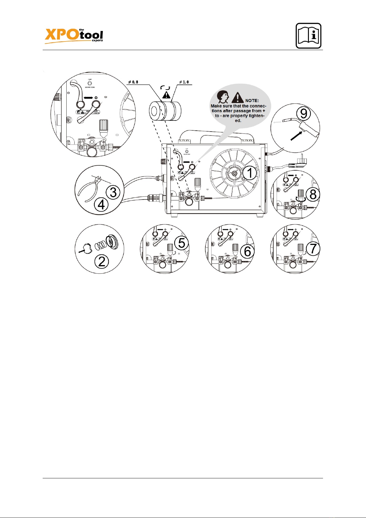
•The device welds best when the welding wire has a diameter of 0.8 mm. In addition, solid or
filler wire with a diameter of 0.6 mm, 0.9 mm, or 1.0 mm can be used as welding wire. However,
it should be noted that the device is only suitable for steel wire welding.
Welding
•The welding result does not only depend on the respective welding machine, but also on the
workpiece and the working environment. Therefore, the user must strictly follow the instructions
in this manual.
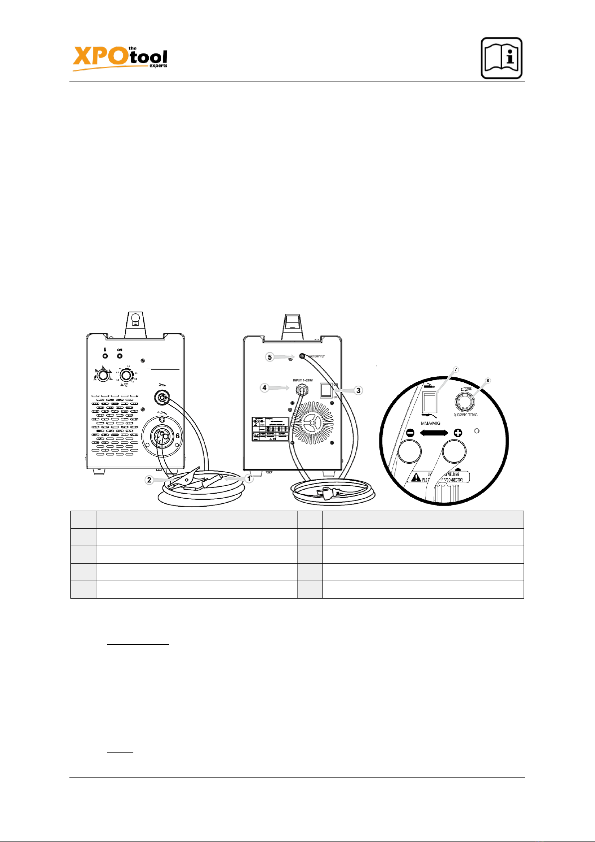
•During welding, electrical current is passed through the welding nozzle to the welding wire and
from there to the workpiece. An earth cable attached to the workpiece returns power to the
device, thereby completing the circuit. The current can flow unhindered if the earth clamp is
properly attached to the workpiece and the point at which the clamp rests on the workpiece is
clean, colourless, and rust-free.
•Shielding gas must be used for welding so that no air mixes with the weld. Carbon dioxide or a
mixture of carbon dioxide and argon is suitable as shielding gas. Some welding wires generate
shielding gas themselves, which is produced when the wire filling melts, which means that there
is no need to use an additional shielding gas.
Safety instructions
The device is safe to use as the plastic cover does not conduct electricity. The welding gun is equipped
with an overheating protection that prevents the device from becoming excessively hot. It also has a
protection from too low or too high input voltage. Nevertheless, numerous dangers can arise from weld-
ing work, and it is imperative that you read the safety instructions carefully and follow them.
Protective equipment
•Do not look into the arc with unprotected eyes, only use a welding protection shield with protec-
tive glass in accordance with DIN. The welding shield must always be used during welding. It
protects your eyes from harmful UV rays and heat from the electric arc.
•The arc and weld spatter cause burns to the skin. Therefore, always wear protective gloves and
clothing when welding.
•When working with a higher setting, also wear a leather apron to protect yourself from welding
spatter.

https://www.XPOtool.com Item 62994 Page 4
The Tool Experts
01 2022-1
Safety during welding gun use
•Parts of the machine, such as the end of the welding wire and the welding gun itself, become
very hot during use. The welding wire is sharp and moves quickly. So be careful when threading
it.
•Never carry the device around while welding with it. It must stand on a level surface. The device
must not be hung up on the shoulder strap. The shoulder strap is only intended for carrying the
device.
•The device must not be placed in the immediate vicinity of or on top of hot objects; otherwise,
the plastic cover could melt.
•Do not move the shielding gas cylinder when the control valve is connected. The gas cylinder
must stand upright and be secured against falling over, e.g., on a wall shelf or a gas bottle
carrier.
Safety and fire protection
•Welding work is hot work. Therefore, the fire protection regulations must be complied with. Pro-
tect your surroundings from weld spatter. Remove flammable materials, such as flammable liq-
uids, from near the place where you will weld. Have suitable firefighting equipment ready at this
point.
•Note that some workplaces also present special dangers, such as fire or explosion hazard, if
welding is carried out in closed environments.
•Danger! Sparks can still start a fire hours after they have been generated!
•Attention! It is strictly forbidden to carry out welding work in places where fires and explosions
can easily occur.
Safety and input voltage
•Do not take the welding machine with you into the workpiece to be processed, for example in a
large container or a car.
•Do not place the welding machine on a wet surface.
•Replace damaged cables immediately; they are life-threatening and can cause a fire.
•The cables must not be pinched or rest on sharp edges or on a hot workpiece.
Safety and welding circuit
•Wear dry and undamaged protective clothing to isolate yourself from the welding circuit.
•Do not work on a wet surface.
•Do not use damaged welding cables.
•Do not place the welding gun or earth clamp on the welding machine or any other electrical
device.
Safety and welding fumes
•Provide adequate ventilation.
•Take special precautions when welding metals that contain lead, cadmium, zinc, mercury, or
beryllium.
•A fresh air mask can ensure adequate fresh air supply.
Using the welding machine
The welding machine comes to you ready for use and with a 0.8 mm diameter welding wire attached. If
you are using a welding wire not recommended, make sure that its size and type are appropriate for the
welding gun contact tip, welding wire feed, and device polarity.

https://www.XPOtool.com Item 62994 Page 5
The Tool Experts
01 2022-1
Before using the machine
•The device is delivered in a specially shaped, robust packaging. Nevertheless, upon receipt,
check whether any damage has occurred during transport. Also check if you have received the
device that you have ordered and if all the necessary instructions are included. Please recycle
the packaging material.
•The device must be transported upright.
•Danger! Always lift the device by the handle, never by the welding gun or a cable.
•The device is suitable for both outdoor and indoor use, but should be shielded from heavy rain
and direct sunlight. Store it in a dry and clean place, and protect it from sand and dust when
using or storing it. We recommend using the device only at temperatures between –20 ℃ and
+40 ℃.
•Place the device so that it does not touch hot surfaces or come into contact with sparks and
weld spatters.
•Make sure that air can flow unhindered through the device.
Main components and their names
№
Name
№
Name
1
Welding gun
5
Shielding gas hose connector
2
Earth cable
6
Electrode holder connector
3
Main switch
7
MMA/MIG switch
4
Supply voltage cable
8
Fast wire feeding switch
Cable and hose connections
•Power supply:
◦The device has a 3.3 m long power cable with a plug. Insert the plug into the power supply
socket.
◦Note! The power supply must have a 16 A delayed fuse.
◦If you use an extension cable, its cross-section must at least correspond to the cross-section
of the voltage input cable (3×2.5 mm²). The extension cable must not be longer than 50 m.
◦The welding machine can also be operated via a generator. The minimum output of the
generator must be 3.5 kVA, 6.0 kVA being recommended to use the entire capacity of the
device.
•Earth: The earth cable is already connected to the device. Clean the surface of the workpiece
and attach the earth clamp to it to create a closed and interference-free circuit necessary for
welding.

https://www.XPOtool.com Item 62994 Page 6
The Tool Experts
01 2022-1
•Welding gun:
◦The welding gun is already connected to the device. It conducts the welding wire, the shield-
ing gas and the electric current to the weld. When the welding gun trigger is pressed, shield-
ing gas is released and the wire feed begins. The arc ignites when the welding wire touches
the workpiece.
◦The welding gun neck can be rotated 360°. When you turn the welding gun neck, make sure
that it is turned almost all the way towards the ground. This will prevent it from being dam-
aged and overheating.
◦Note! Before using a welding wire with a diameter other than 0.8 mm, the contact tip of the
welding gun must be changed to match the thickness of the wire.
•Shielding gas:
◦Carbon dioxide or a mixture of argon and carbon dioxide, which displaces the air in the area
of the arc, is used as shielding gas for steel wire welding. Both the workpiece thickness and
the welding performance determine how much shielding gas has to be released.
◦A protective gas hose 4.5 m long is supplied with the device. Connect the bayonet lock of
the shielding gas hose to the hose connection of the device and the other end of the shield-
ing gas hose to the control valve of the gas cylinder.
№
Explanation
1
Connect the hose to the control valve
on the gas cylinder and tighten the
connection.
2
Adjust the flow rate with the control
valve screw. A suitable flow rate is
between 8 and 15 ℓ⁄min.
3
Close the control valve again after
use.
Note! Use a shielding gas appropriate for the material being welded. The gas cylinder must stand upright
and must not tip over. Only then do you connect the control valve.
Welding wire
The welding gun is already connected to the positive pole of the device. This means that solid steel wire
can be welded with no further adjustments.
The wire feed roll groove is set at the factory so that welding wires with a diameter of 0.8–1.0 mm can
be used. If you want to use welding wire with a diameter of 0.6 mm, you must adapt the feed roll groove.

https://www.XPOtool.com Item 62994 Page 7
The Tool Experts
01 2022-1
1. Open the wire feeder from the pressure control lever.
2. Switch on the device at the main switch.
3. Press the welding gun trigger and move the feed roller to a position in which the locking screw
is facing up and can be loosened.
4. Switch the device off again at the main switch.
5. Using a 2.0 mm Allen key, turn the feed roller set screw approximately half a turn.
6. Pull the feed roller off the spindle.
7. Turn the feed roller and place it back on the spindle until it is all the way down. Make sure that
the screw is facing up.
8. Re-tighten the feed roller locking screw.

https://www.XPOtool.com Item 62994 Page 8
The Tool Experts
01 2022-1
Threading in the welding wire
1. Open the spool housing by pressing the open button and insert the wire spool so that it can
rotate counter-clockwise. Either a 5 kg (200 mm diameter) or 1 kg (100 mm diameter) wire spool
can be inserted into this device.
2. Secure the spindle with the spindle lock.
3. Loosen the wire end from the spindle, but always hold it tight.
4. Pull the wire end about 20 cm (8 inches) away from the spool and straighten the pulled-out wire
end; then cut the wire where it has just been pulled.
5. Open the pressure control lever, which in turn opens the feed gear.
6. Thread the wire through the rear wire feed and up to the welding gun wire feed.
7. Close the feed gear again and secure it with the pressure control lever. Make sure that the wire
runs in the feed roll groove.
8. Set the compression pressure on the pressure control lever, but no more than to the middle of
the scale. If the pressure is too high, metal particles are removed from the surface of the wire,
which can damage the wire. If the pressure is too low, the feed gear will slip and the wire will
not run smoothly.
9. Press the welding gun trigger and wait for the wire to come out.
10. Close the cover of the spool housing.
Caution! Do not point the welding gun at yourself or at others when the wire is going in and out, or put
your hand in front of the contact tip; the cut end of the wire is very sharp! Also, keep your fingers away
from the feed rollers as they could be pinched between the rollers.

https://www.XPOtool.com Item 62994 Page 9
The Tool Experts
01 2022-1
Reversing polarity
When using certain welding wires, the welding gun should be connected to the negative pole, which
reverses the polarity. Check the welding wire packaging to find out which polarity is recommended.
1. Pull out the power plug.
2. Bend the rubber cover of the earth cable so that the cable can be pulled out.
3. Remove the nuts and washers holding the poles in place. Pay attention to the order in which
the washers are attached!
4. Swap the cables.
5. Reinstall the washers and tighten the nuts with a wrench.
6. Reattach the rubber cover of the ground cable terminal firmly. This rubber cover must always
sit on the ground cable pole as protection.

https://www.XPOtool.com Item 62994 Page 10
The Tool Experts
01 2022-1
Controls and indicator lights
Front panel of the machine
№
Name
№
Name
1
Overheat indicator light
4
Arc length trimmer
2
Welding power control
5
MMA/MIG switch
3
Standby indicator light
•The settings described apply to MMA welding.
•The welding power is adjusted depending on the thickness of the welding plate. The device also
has an arc length regulator.
•The indicator lights show when the machine is on standby or when overheating occurs.
•When the device is switched on, the green standby lamp lights up. The main switch light also
lights up at the same time. If the device overheats, the input voltage is too low or too high,
welding will stop immediately and the yellow overheat indicator light will illuminate. It goes out
again when the device is ready for operation again. Make sure that there is enough space
around the device for an unobstructed flow of air, which is used to cool the device.
Welding power adjustments
•When the welding power is adjusted depending on the welding plate thickness, this also influ-
ences the wire feed speed and the electrical current transmitted to the wire. This enables weld-
ing work in many different situations. But the type of connection and the root gap also influence
how much welding power is required.
•Set a suitable value with the aid of the welding power control, which is matched to the thickness
of the welding sheet on which the fillet welds are to be made. If you want to process sheets of
different thicknesses, set an average value.
•The sheet thickness scale is given in millimetres and relates to 0.8 mm wire. If you are using a
0.6 mm wire, set the welding power a little higher than the sheet thickness, and a little lower
with 0.9–1.00 mm wire.

https://www.XPOtool.com Item 62994 Page 11
The Tool Experts
01 2022-1
•Note! When welding for the first time, we recommend that you set the arc length regulator to
the medium value.
Arc length regulator
•The arc length control shortens or lengthens the arc and influences the welding temperature. A
shorter arc is less hot, a longer arc is hotter. The arc length regulator also influences the welding
properties of the arc and the formation of weld spatter, depending on the diameter of the welding
wire and the shielding gas used.
•If the weld is too convex, the arc is too short/cold. In this case, the arc should be made
longer/hotter by turning the control clockwise.
•If, on the other hand, you want a colder arc, e.g., lest a hole be burned in the base material,
shorten the arc by turning the control counter-clockwise. In this case, adjusting the welding
performance can also help.
•As soon as the arc is shortened, it usually no longer needs to be readjusted if the sheet thickness
changes.
Service
When servicing the device, the frequency of use and the environmental conditions should also be con-
sidered. If it is used properly and regularly maintained, you will be spared unnecessary malfunctions.
Caution! Unplug the power cord before handling electrical cables.
Daily service
•Remove welding spatter from the contact tip of the welding gun and check the condition of the
parts. Replace damaged parts immediately.
•Check that the insulating tips of the welding gun neck are intact and in the right places. Replace
damaged insulating parts immediately.
•Check if the cables of the welding gun and the earth cable are tight.
•Check the condition of the input power cable and the welding cable and replace any damaged
cables.
Servicing the wire feed
•Service the wire feed at least every time a different wire spool is used.
•Check if the wire feed roller groove is worn, and replace the wire feed roller if necessary.
•Clean the welding wire feed of the welding gun with compressed air.

https://www.XPOtool.com Item 62994 Page 12
The Tool Experts
01 2022-1
Cleaning the wire guide
The pressure exerted by the feed roller on the welding wire causes metal dust to be removed from its
surface; this dust then reaches the wire guide. If it is not cleaned, it will gradually clog, causing the feeder
to malfunction. Clean the wire guide as follows:
1. Remove the welding gas nozzle, the contact tip and the contact tip adapter from the welding
gun.
2. Use a compressed air gun to blow compressed air onto the wire guide.
3. Blow out the wire feeder and the spool housing with compressed air as well.
4. Reinstall the parts of the welding gun. Tighten the contact tip and adaptor with a wrench.
Replacing the wire guide
If the wire guide is too worn or completely clogged, it must be replaced with a new one as follows:
1. Loosen the connection between the welding gun and the device:
a) Loosen the connection of the cable clamp of the welding gun power cable by unscrewing
the screws.
b) Disconnect the power cable of the welding gun from the connection terminal of the device.
c) Remove the connector of the trigger conductors from the device.
d) Unscrew the fastening nut of the welding gun.
e) Gently pull the gun away from the device. This will allow all parts to come out through the
cable opening on the front.
2. Turn the wire guide fastening nut; this will expose the end of the wire feed.
3. Pull the welding gun cable straight and pull the wire guide out of the gun.
4. Slide a new wire guide into the gun. Make sure that the end of the wire guide also slides into
the adaptor of the contact tip and that an O-ring sits on the device-side end of the feed.
5. Re-tighten the mounting nut to secure the wire guide.
6. Cut the wire feed 2 mm in front of the fastening nut and file the sharp edges of the cut.
7. Reattach the welding gun to its place and tighten the individual parts with a wrench.
Troubleshooting
Problem
Cause
Solution
Welding wire does
not move or wire
feeder is tangled.
Wire feed roller, wire guide
or contact tip defective
Check if the feed roller is too tight or too loose.
Check if the guide groove is too worn.
Check if the wire guide is clogged.
Check if there are weld spatters on the contact tip
and if the hole is cramped or has become too large
due to wear.
Operating light is not
lit.
No supply voltage
Check the fuses.
Check the input power cord and plug.
Poor welding result
Welding performance is in-
fluenced by various cir-
cumstances.
Check the settings of the welding power regulator
and the welding arc length regulator.
Check if the earth clamp is properly attached, the
connection point is clean, and the cable and con-
nectors are undamaged.
Check the shielding gas flow at the welding gun tip.
Check if the input voltage is uneven, too low or too
high.

https://www.XPOtool.com Item 62994 Page 13
The Tool Experts
01 2022-1
Overheat protection
is lit.
Device overheated
Check if the air used for cooling can flow unhin-
dered.
Wait until the indicator light goes out again after the
device has been overloaded.
Check if the supply voltage is too low or too high.
Technical specifications
Model
MIG/MMA-160
Wire feed
inner
Input voltage (
V
)
1~220 V ±10 %
1~230 V ±10 %
Wire feed speed (m⁄min)
2.5–12
Frequency (㎐)
50/60
Roller diameter (㎜)
R=200
Apparent power (
kVA
)
4.5
Wire diameter (㎜)
0.6/0.8/1.0
Current (
A
)
50~160
Dimensions (㎜)
420(L)×220(B)×350(H)
Rated duty cycle (
%
)
60
Weight (㎏)
10.6
Power factor
0.93
Insulation class
H
Efficiency (
%
)
85
Degree of protection
IP21S

https://www.XPOtool.com Item 62994 Page 14
The Tool Experts
01 2022-1
Disposal regulations
EU guidelines regarding the disposal of scrap electric appliances (WEEE, 2012/19/EU) were imple-
mented in the law related to electrical and electronic equipment and appliances.
All WilTec electric devices that fall under the WEEE regulations are labelled with the crossed-out
wheeled waste bin logo. This logo indicates that this electric equipment must not be disposed with the
domestic waste.
The company WilTec Technik GmbH has been registered in the German registry EAR under the WEEE-
registration number DE45283704.
Disposal of used electrical and electronic appliances
(intended for use in the countries of the European Un-
ion and other European countries with a separate col-
lection system for these appliances).
The logo on the article or on its packaging points out
that this article must not be treated as normal house-
hold waste but must be disposed to a recycling collec-
tion point for electronic and electrical waste equipment.
By contributing to the correct disposal of this article you
protect the environment and the health of your fellow
men. Environment and health are threatened by inap-
propriate disposal.
Material recycling helps reduce the consumption of raw materials.
Additional information on recycling this article can be provided by your local community, municipal waste
disposal facilities, or the store where you purchased the article.
Address:
WilTec Wildanger Technik GmbH
Königsbenden 12 / 28
D-52249 Eschweiler
Important notice:
The reprint or reproduction, even of excerpts, and any commercial use, even in part, of this instruction
manual require the written permission of WilTec Wildanger Technik GmbH.
This manual suits for next models
1
Table of contents
Other XPOtool Welding System manuals
Popular Welding System manuals by other brands

Clarke
Clarke AT165 Operation & maintenance instructions

MasterCraft
MasterCraft 058-8194-4 instruction manual

Pro Spot
Pro Spot PR-205 instruction manual

Lincoln Electric
Lincoln Electric INVERTEC V350-PRO CE Service manual

Saf-Fro
Saf-Fro AVISO 300 AC/DC SYNCHRO manual

HBS
HBS ACCU-TWIN 92-10-2380A operating manual

WARPP
WARPP INTIG 316 AC/DC Operator's manual

tresnar
tresnar 4614 MMA-145 instruction manual

KICKING HORSE
KICKING HORSE P40 Operation manual

Sealey
Sealey MIGHTYMIG170.V2 quick start guide

P.Lindberg
P.Lindberg Extreme 160III Original manual

Lincoln Electric
Lincoln Electric PIPELINER 11498 Operator's manual