XPOtool MIG-120 User manual

Operating Manual
IGBT Welding Machine 120A (MIG, MMA, TIG, FCAW)
64234
Illustration similar, may vary depending on model
Read and follow the operating instructions and safety information prior to initial operation.
Technical changes reserved!
Illustrations, functional steps, and technical data may deviate insignificantly due to continuous further
developments.
Updating the documentation
If you have suggestions for improvement or have found any irregularities, please contact us.

https://www.XPOtool.com Item 64234 Page 2
The Tool Experts
09 2023-1
The information contained in this document may alter at any time without prior notice. No part of this
document may be copied or otherwise duplicated without prior written consent. All rights reserved.
WilTec Wildanger Technik GmbH cannot be held liable for any possible mistakes in this operating man-
ual, nor in the diagrams and illustrations shown.
Although WilTec Wildanger Technik GmbH has made every possible effort to ensure that this operating
manual is complete, accurate, and up-to-date, errors cannot be ruled out entirely.
If you have found an error or wish to suggest an improvement, we look forward to hearing from you.
Send us an e-mail to:
or use our contact form:
https://www.wiltec.de/contacts/
The most recent version of this manual in several languages can be found in our online shop:
https://www.wiltec.de/docsearch
Our postal address is:
WilTec Wildanger Technik GmbH
Königsbenden 12
52249 Eschweiler – Germany
To return your goods for exchange, repair, or other purposes, please use the following address. Atten-
tion! To allow for a trouble-free complaint or return, it is important to contact our customer service team
before returning your goods.
Retourenabteilung
WilTec Wildanger Technik GmbH
Königsbenden 28
52249 Eschweiler – Germany
E-mail: service@wiltec.info
Phone: +49 2403 55592–0
Fax: (+49 2403 55592–15)

https://www.XPOtool.com Item 64234 Page 3
The Tool Experts
09 2023-1
Introduction
Thank you for choosing to purchase this quality product. To minimise the risk of injury, we ask you to
always take some basic safety precautions when using this product. Please read this operating manual
carefully and make sure that you understand it.
Keep these operation instructions in a safe place.
Safety instructions
Read
operating manual!
Use
welding mask!
Use
face mask!
Wear
protection clothes!
Wear
hand protection!
Wear
hearing protection!
Wear
foot protection!
ATTENTION: If you hand the unit over to another person, please hand over these operating instruc-
tions/safety instructions as well. We assume no liability for any accidents or damage caused by non-
compliance with this manual or the safety instructions.
ATTENTION: For your own safety, do not operate the welding machine until AFTER reading the safety
instructions.
ATTENTION: Do ONLY use the device in accordance with the intended use defined in this manual. The
welding machine must NOT be used:
•in rooms with insufficient ventilation
•in damp or wet environments
•in explosion-endangered areas
•for thawing pipes
•near persons with a pacemaker
•near inflammable materials
Incorrect use of this machine might be dangerous for persons, animals and objects. The user of this
device is responsible for his or her own safety and the safety of other persons. Make sure to read and
follow the instructions.
Safety instructions
General safety and accident prevention regulations
•In addition to the instructions in this operating manual, the general safety and accident pre-
vention regulations of the legislator must be regarded.
•Hand over this manual to third parties. Make sure that third parties only use this product after
receiving the necessary instructions.
•The device is not intended for use by persons (including children) with impaired or limited phys-
ical and mental abilities or lack of experience and/or real knowledge, unless they are supervised

https://www.XPOtool.com Item 64234 Page 4
The Tool Experts
09 2023-1
by a person responsible for their safety or follow the instructions made by this person on how to
correctly use the device. Children should be supervised to ensure that they do not play with the
device. Children must not use this device.
•Always pay attention and concentrate on what you are doing. Do not perform work with this
product when being unalert or influenced by alcohol, drugs, or medicine. Even a short moment
of inattention during the use of this device might cause severe accidents and injuries.
Safety instructions concerning the use of the welding machine
•Ensure a secure stand. Make sure to mount the device on a stable and safe surface.
•Avoid contact with hot parts. Do not touch any hot parts of this device. Keep in mind that
various components, storing heat, might cause burns even after the use of this device.
•Check for any damages. Before using the device, check it for possible damages. If the device
is damaged, it must not be put into operation.
•Do not use sharp objects. Never introduce sharp and/or metallic objects in the inside of the
device.
•Do not use the device incorrectly. Only use the device according to the intended use defined
in this manual.
•Perform regular checks. The use of this device can cause wear and tear of certain parts.
Therefore, regularly check the device for possible damages and faults.
•Correct use of the power cable. Never disconnect the plug by pulling on the power cord.
Protect all cords from oil, sharp edges, and high temperatures. During work, make sure not to
touch the cables with hot objects. The power cable must not be damaged. If the power cable is
damaged, it must be replaced with a new one.
•The unit should not be enclosed by objects, nor should it be placed directly against a
wall, so that sufficient air can get through the opening slots.
•Arc welding produces sparks, welded metal parts and smoke. Therefore, make sure to
remove all flammable substances and/or material from the work area.
•Do not weld on containers, tanks or pipes that may have contained flammable liquids or
gases.
•Avoid any direct contact with the welding circuit; the open-circuit voltage between the electrode
holder and the earth clamp can be dangerous.
•Do not store or use the device in damp/wet areas or in the rain.
ATTENTION:
•Welding arc radiation can cause eye damages and skin burns.
•Arc welding produces sparks and drops of molten metal. The welded piece begins to glow and
remains hot for a long time.
•Arc welding produces vapours that can be harmful. An electric shock can be fatal.
•Define safety distances for the welding zone and make sure that unauthorised persons and/or
persons not wearing protective clothing cannot enter the work zone. Danger caused by flying
sparks!
•Protect yourself and bystanders from all possible dangers caused by arc welding.
Hazard sources during arc welding
Arc welding involves a number of potential hazards. Therefore, it is very important that the
welder observes the following regulations in order not to endanger him/herself and other per-
sons, to avoid injury to persons and to avoid damage to the machine.
•Should contact voltages form, immediately switch off the device and have it checked by a
qualified person.
•Make sure that the electrical contacts and the device are always in perfect condition.
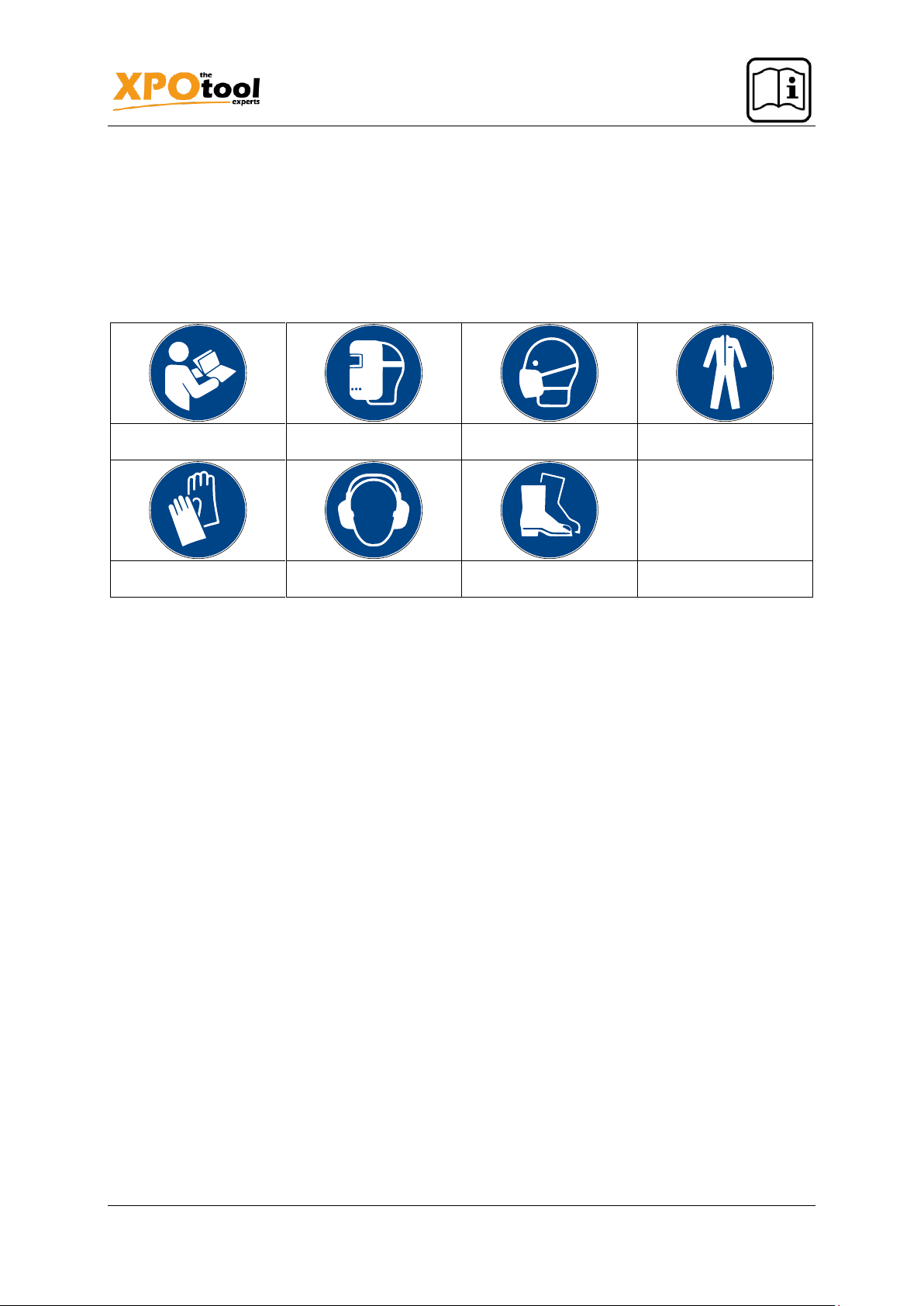
•During welding, always wear insulating gloves on both hands. These offer protection
against electric shocks (e.g., when the welding circuit is at open-circuit voltage), harmful radia-
tion (heat and UV rays), glowing metal, and weld spatter.
•Wear sturdy footwear with insulation Low shoes are not suitable as falling, glowing metal
drops can cause burning.
•Wear suitable clothing no synthetic clothing.

https://www.XPOtool.com Item 64234 Page 5
The Tool Experts
09 2023-1
•Do not look into the arc without protecting your eyes. Only use welding shields with DIN-
compliant protective glass. Besides light and heat radiation causing glares and burns, the weld-
ing arc also emits ultraviolet rays. If the protection is inadequate, these invisible ultraviolet rays
cause very painful conjunctivitis (pinkeye) that only becomes noticeable a few hours later. In
addition, UV radiation has a comparable effect to sunburn on unprotected parts of the body.
•Persons or assistants in the vicinity of the arc must be informed of the dangers and
equipped with the necessary protective equipment. If necessary, install protective walls.
•No welding works may be performed on containers where gases, fuels, mineral oils, etc.
are stored or have been stored, even in case they have been emptied a long time ago;
residues might cause explosions.
•Special regulations apply in potentially explosive atmospheres.
Risk of accident caused by electric shock
With no welding arc burning, there is a no-load voltage U0 between the earth terminal and elec-
trode holder. This voltage can be dangerous to life if the welder touches the metal clamping jaws
of the electrode holder and the piece with unprotected hands.
Narrow and hot rooms
•Performing work in narrow or hot rooms is a special risk situation that necessitates additional,
special protective clothing to be worn. Insulating pads (e.g., rubber mats, wood grates, etc.)
must possibly be used.
•Risk of accidents caused by deficiency of air in narrow rooms. Considerable quantities
of vapour and gas form during welding. Make sure that vapours and gases can escape
through suitable vents. However, do not take in oxygen. This would increase the risk of fire.
Protective clothing
During work, the welder’s entire body must be protected from radiation and burns by wearing clothing
and facial protection.
Fire hazard due to flying sparks
If melted or glowing metal and slag fall on flammable material, it may ignite and cause a fire. Therefore,
remove any inflammable objects from the work zone before beginning to weld.
Explosion hazard
Both welding sparks and the hot welding spot can cause explosions. Therefore, do not use the unit in
potentially explosive zones where flammable liquids, gases and paint mists are present.
Furthermore, note the following:
•Immediately remove the electrode from its holder after finishing welding work to avoid a welding
arc from accidentally forming.
•During operation of the device, do not put the electrode holder on the welding machine or on
any other electric device.
•Before finishing work, do not touch the electrode or another metal objects in contact with the
electrode.
•Immediately disconnect the power supply after finishing welding work.
•Make absolutely sure that no cable wraps around your body.
•Make absolutely sure that you do not stand between the earth terminal and electrode
holder during welding. The electrode holder and earth terminal must always be on the
same side.
Handling shielding gas bottles
•Incorrect handling of shielding gas bottles! Wrong handling of shielding gas bottles can lead
to severe injuries or even death.

https://www.XPOtool.com Item 64234 Page 6
The Tool Experts
09 2023-1
•Obey all instructions given by the manufacturer of the gas and the decree on pressure gas!
•Place the shielding gas bottle in the spot previewed and secure it with fixing elements!
•Avoid any heating up of the shielding gas bottle!
Residual risks
Despite obeying to the intended use, residual risks cannot be fully excluded.
Due to the type and design of the device, the following risks can result:
a) eye injuries by glazing,
b) injuries caused by burns after touching hot parts of the device or piece,
c) risks of accident and fire caused by flying sparks or slag particles when not being sufficiently
protected,
d) harmful consequences for health due to smoke and gases in case of insufficient extraction in
closed rooms
To ensure that you can enjoy your welding machine for a long time, it should regularly be main-
tained and cleaned. It is advisable to have the device checked every six months. Adjust the
maintenance interval when used frequently. Completely disconnect the welding machine from
the power supply before performing maintenance works. The unit is in most cases maintenance-
free. However, the following works should be performed:
•Keep the safety guards, air vents and motor housing as free of dust and dirt as possible. Rub
the device with a clean cloth and remove rougher dirt with the help of compressed air the pres-
sure of which should be as low as possible. Hereby, apply the lowest possible pressure.
•The device should be cleaned after each use.
•Check the condition of the welding cables, electrode holder, and earth terminal.
•The electrode holder must regularly be cleaned from weld spatters and contaminations. Apply
release agent after cleaning to reduce adhesiveness for spatters.
•Cables with worn or damaged insulation are potential hazards that may affect the operation of
the unit.
•Check whether all screw, bolts, and nuts are firmly tightened. Should they be loose, re-tighten
them.
Description
The MIG 120 is a 3 in 1 welding machine which can be used for MIG, TIG and MMA welding.
When in MIG mode, you can choose between welding with gas and welding with flux cored wire (FCAW).
(Selection button on the welding machine front)
In addition, you can choose between manual and synergic operation. When operating in synergic mode,
the operating voltage and the feed speed do not need to be set separately. This makes operation easy
and helps to achieve a good welding effect. Manual operation, on the other hand, allows the user to
adjust both the output voltage and the output current.
To use the machine in lift TIG welding mode, a lift TIG torch is required (not included in the scope of
delivery).
The MMA mode is suitable for electrodes from 1.6 to a maximum of 3.2 mm.
Other advantages of the welding machine:
•reliable and stable IGBT inverter technology
•tolerance with unstable working voltage
•electric choke control, easy arc start, less weld spatter and stable welding current
•synergic characteristics for easy use
•manual adjustment for individual user requirements

https://www.XPOtool.com Item 64234 Page 7
The Tool Experts
09 2023-1
•greatly reduced number of electronic components used and improved reliability of the circuit,
compared to conventional welders
•can achieve an efficiency of more than 85 %
Technical specifications
Control panel
№
Description
№
Description
1
Operation light
9
Digital display
2
OC – LED
10
Controller output voltage
3
Controller output current
11
Setting speed of wire feed
4
Negative terminal (–)
12
MIG torch
5
Positive terminal (+)
13
Gas connection
6
Input current
14
Earthing screw
7
Power switch
15
Cable for changing polarity*
8
Fan
16
Control panel
Model name
MIG-120
Input voltage (V)
220V-240V
Frequency (㎐)
50
Current (A)
120
No-load voltage (V)
62
Duty cycle (%)
35 %
Wire feed
Integrated
Electrode diameters (㎜)
1.6–3.2
Wire Spool (㎜⁄㎏)
0.8–0.9⁄0.45–1
Insulation class
F
IP code
IP21S

https://www.XPOtool.com Item 64234 Page 8
The Tool Experts
09 2023-1
*It is possible to change between positive and negative polarity for different welding procedures.
During MIG welding with gas, the cable for changing polarity (15) is plugged into the positive terminal (5).
During FCAW welding with flux cored wire, the cable for changing polarity (15) is plugged into the neg-
ative terminal (4).
Preparation MIG welding
Connection to power supply
The MIG 120 welder requires a 230 V AC connection with 50 Hz. Use the appropriate power supply and
ensure that the unit is earthed.
Installation
Attention! The welding unit is delivered ready for use, with a 0.8 mm welding wire already fitted. When
using a welding wire that is not recommended, make sure that its size and type are suitable for the
contact tip of the welding gun, the wire feed, and the polarity of the machine.
Adapting the wire feed
The machine is prepared for the use of 0.8 mm cored wire on delivery. If you want to use 1.0 mm wire,
the guide groove needs to be adjusted. Adapt the guide groove as follows:
1. Open the cover of the welding machine.
2. Lift the pressure regulator (1) and shift the pressure control lever (2) away from the feed roll.
3. Remove the locking screw (3) of the feed roll by turning it counter-clockwise and moving it off
the roll.
4. Remove the feed roll and pay attention to the wire sizes engraved on both sides of the roll.
5. Insert the roll so that the engraved size on the side of the roll is directed towards you.
6. Reinstall the locking screw (3) of the feed roll.
7. Move the pressure control lever (2) back to the original position and re-adjust the pressure reg-
ulator (1).
Inserting the wire spool
This welding machine is only suitable for wire spools with a diameter of 10 cm. Insert the wire spool as
follows:

https://www.XPOtool.com Item 64234 Page 9
The Tool Experts
09 2023-1
1. Open the welding machine cover, remove the locking screw (1) and the spacer from the wire
spool.
2. Slide a 10 cm diameter wire spool onto the wire shaft and reattach the spacer and the locking
screw.
Note! This welder can only be used with welding wire in sizes 0.8 or 1.0 mm.
Threading the welding wire to the welding gun
1. Switch off the power switch and disconnect the welding machine from the power supply.
2. Remove the contact tip and nozzle from the end of the welding gun.
3. Make sure the feed roll is installed in the correct position for the wire size you are using.
4. Release the pressure regulator (1) and lift the pressure control lever (2). Make sure that the feed
roll matches the size of the welding wire used (see previous section). The feed roll is pre-in-
stalled for 0.8 mm wire.
5. Carefully unwind the welding wire from the wire spool.
Note! Do not let go of the wire. Otherwise, the entire coil could unwind.
6. Cut the bent end of the wire and straighten the welding wire to a length of about 8 cm.
7. Thread the welding wire into the wire feed (4) via the feed roll up to the wire feed of the welding
gun.
8. Move the pressure control lever (2) back to the original position and re-adjust the pressure reg-
ulator (1).
9. Now reconnect the welder to the power supply and turn the power switch back on. Set the wire
feed speed as desired.
10. Point the gun away from yourself and others and pull the trigger to start feeding the wire. Note!
While doing this, watch the feed roll to see if there is any slippage between the feed roll and the
wire spool. If there is one, switch the machine off and tighten the pressure regulator (1). Then
check again to see if it occurs again.
11. As soon as the wire comes out of the gun, re-place the contact tip and nozzle. Cut off approx.
0.5–1 cm wire in front of the contact tip.
Attention!
Do not point the welding gun towards your own body or towards other persons while the wire is being
inserted or coming out; never hold the hand in front of the contact tip; the cut-off end of the wire is
extremely sharp! Neither hold your fingers near the feed rolls; they risk to be pinched between them.
Use
Using this welding machine, you will be able to perform many different welding applications; however,
these must be trained and tested before you can embark on a real project. The welding process de-
scribed in the following is to be considered as base for beginners.

https://www.XPOtool.com Item 64234 Page 10
The Tool Experts
09 2023-1
1. Always wear a welding helmet, gloves, a long-armed shirt, and long-legged trousers when weld-
ing.
2. Connect the earth clamp to the pieces that you will be welding. Make sure that the contact point
of the earth clamp is a clean piece of metal free from paint, grease, rust, oil, etc. It is advisable
to connect the earth clamp as close to the welding area as possible.
3. Check the welding area making sure that it is free from paint, grease, rust, oil, etc., too.
4. Connect the welding machine to the power supply and switch on the power switch.
5. Press the trigger of the welding gun. The gun must point away from your body. Then release
the trigger and cut the wire to a length of about 0.6 cm.
6. Introduce the wire end protruding from the gun into the spot to be welded.
7. Hold the welding gun perpendicularly to the material base and tilted back by 15–20°.
8. When you pull the trigger and the arc has ignited, a puddle of molten material will form. This is
the weld bead that follows the movement of the welding gun. The size of the puddle of molten
material dictates how fast the welding gun should be moved.
9. Release the trigger of the welding gun to pause while welding.
10. After welding, switch off the device and disconnect it from the power supply.
Preparation MIG welding
Welding with shielding gas
Connect the cable for changing polarity (15) to the positive terminal (+) and the earth clamp to the neg-
ative terminal (–).
MIG synergic mode
In synergic mode, mainly controller 3 is needed for the output current. Controller 10 for the output voltage
is only needed for fine tuning.
MIG manual mode
Controller 10 is used to set the output voltage, controller 3 to set the output current / wire feed speed.
•Shielding gas:
◦The shielding gas used is an inert gas that displaces the air in the area of the arc. The
amount of shielding gas to be used is determined by the thickness of the welding piece and
the welding power.
◦Connect the bayonet coupling of the shielding gas hose with the hose connection of the
device; the other end of the shielding gas hose is connected to the regulating valve of the
gas cylinder.
№
Explanation
1
Connect the hose to the regulating
valve of the gas cylinder and tighten
the connection.
2
Adjust the flow with the help of the
screw of the regulating valve. A suit-
able flow rate ranges between 8 and
15 ℓ⁄min.
3
After use, close the regulating valve.

https://www.XPOtool.com Item 64234 Page 11
The Tool Experts
09 2023-1
Note! Only use shielding gases suitable for the material that you are welding on. The gas cylinder must
stand upright. It must be prevented from tipping over. Only then connect the regulating valve.
FCAW mode / flux cored welding
Connect the cable for changing polarity (15) to the negative terminal (–) and the earth clamp to the
positive terminal (+).
When using self-protecting flux cored wires, no external gas is required. Ensure that the wire size, torch,
and contact tip match before using the unit.
Preparation MMA welding
Connect the earthing cable to the positive terminal (+) and the electrode holder cable to the negative
terminal (–) on the front. Then select the MMA mode on the control panel (16). The LED lights up to
confirm the selection. You can now start the welding process.
Preparation TIG welding
Connect the earthing cable to the positive terminal (+) and the TIG torch to the negative terminal (–) on
the front. Then select the TIG mode on the control panel (16). The LED lights up to confirm the selection.
You can now start the welding process.
Problem
Possible solution
Fan does not work, no output current
1. Check if the power switch is switched off
or if it is defective.
2. Check for loose cables inside the ma-
chine.
3. The unit is not plugged in.
Display normal, fan is working normally, yet there
is no output current
1. Check if the inner cable is in good condi-
tion.
2. Check that the internal connections are
correct.
3. Make sure that all switches are ready for
operation.
Fan works, but OC LED is on
1. Overvoltage protection activated – allow
the unit to remain unused for 5 min and
try again.
2. Circuit board damaged.

https://www.XPOtool.com Item 64234 Page 12
The Tool Experts
09 2023-1
Regulations for waste disposal
The Waste Electrical and Electronic Equipment Directive (WEEE Directive, 2012/19/EU) of the EU was
implemented in the German law related to electrical and electronic equipment and appliances.
All WilTec electric devices that fall under the WEEE directive are labelled with the symbol of a crossed-
out wheeled rubbish bin. This symbol indicates that this electric device must not be disposed of with the
domestic waste.
WilTec Technik GmbH is registered with the German registration authority EAR (Stiftung Elektro-
Altgeräte Register) under the WEEE-registration number DE45283704.
Disposal of used electrical and electronic devices (in-
tended for use in the countries of the European Union
and other European countries with a separate waste
collection system for these devices).
The symbol on the packaging or the product itself indi-
cates that this product must not be treated as normal
domestic waste but must be disposed of at a recycling
collection station for electrical and electronic waste.
By disposing of this product correctly, you contribute to
the protection of the environment and the health of your
fellow people. Inappropriate disposal threatens the en-
vironment and health.
Material recycling helps to reduce the consumption of raw materials.
Additional information about the recycling of this product can be provided by your local commune, the
municipal waste disposal facilities, or the store where you purchased the product.
Address:
WilTec Wildanger Technik GmbH
Königsbenden 12 / 28
52249 Eschweiler Germany
Important note:
Reproduction and any commercial use (of parts) of this operating manual, requires a written permission
of WilTec Wildanger Technik GmbH.
This manual suits for next models
2
Other XPOtool Welding System manuals
Popular Welding System manuals by other brands

ESAB
ESAB ESABMig 325 instruction manual

ProMeister
ProMeister MIG 200 Translation of original operating instructions

Oerlikon
Oerlikon CITOSTEEL III 420 Instruction for operation and maintenance

AGM
AGM JS-1 instruction manual

GYS
GYS INVERTER 2500 instruction manual

ESAB
ESAB Caddy Arc 251i instruction manual