XpressFill XF2500 User manual

XpressFill XF2500


Congratulations on the purchase of your XpressFill Bottle filling machine.
Thank you for choosing our handcrafted bottle filler as the technology to bottle your passion. We look forward to
assisting you in experiencing the best performance from your filler.
This manual is written with your safety and convenience in mind. We highly recommend reading the manual before
using your filler for the first time.
If you have any questions or comments, please do not hesitate to contact us.
XpressFill Systems LLC
265 Prado Road, Suite 1
San Luis Obispo, CA 93401
US
805.541.0100
Toll free 844.361.2750
www.xpressfill.com
Important Safety Instructions
Misuse of the bottle-filling machine can result in serious injury or death. Do not use the machine in any way not
covered in this manual or for any purpose other than those explained in the following pages.
Severe product damage and/or injury could result from the use of unqualified Service Technicians or non-original
replacement parts. All repairs must be performed by a qualified Service Technician or with the approval from an
XpressFill Technician. Only original factory replacement parts should be used.
Electrical shock or fi re could result if the electrical supply for the bottle filler covered in this manual is not correctly
installed or if the bottle filler has been improperly grounded. Do not use the bottle filler covered in this manual
unless you are certain the electrical supply has been correctly installed and the bottle filler has been properly
grounded.
265 Prado Road, Suite 1 | San Luis Obispo, CA 93401 | 805.541.0100 | xpressfill.com | [email protected]
3| XpressFill Systems LLC

Safety Warnings

Table of Contents
1Introduction
2Know Your Filler
3Set Up Your Filler
4Operating Procedures
5Troubleshooting
6Cleaning and Sanitizing
7 Additional Information
265 Prado Road, Suite 1 | San Luis Obispo, CA 93401 | 805.541.0100 | xpressfill.com | [email protected]
5| XpressFill Systems LLC
1
Introduction
XpressFill Product Guarantee
We guarantee our products to be free of defects in materials and workmanship. The filler will be repaired or replaced
if, upon inspection at the factory, the filler is found to be defective in materials or workmanship.
This guarantee does not apply to damage resulting from normal wear and tear, accident, abuse, negligence or
shipping. The guarantee may be rendered invalid if the customer has made repairs or alteration to the machine
without first consulting XpressFill Systems LLC.

2
Know Your Filler
1. Fill indicator light
2. Fill sequence start / stop switch
3. Quick pressure release switch
4. Interior bottle pressure gauge
5. Interior bottle pressure adjustment knob
6. Bottle foot rest
7. Upper spout / product filling
8. Lower spout / pressurizing, venting & level sensing
9. Bottle neck filling stopper
10. Pneumatic ram
265 Prado Road, Suite 1 | San Luis Obispo, CA 93401 | 805.541.0100 | xpressfill.com | [email protected]
6| XpressFill Systems LLC
The below diagram highlights the important features on your filler, which will be referenced throughout this manual.
Being familiar with each of these and their functions will make your filling experience easier.
1
2
3
4
5
6
7
8
9
10

1. Fill Indicator Light: This green light will turn on
while the liquid is flowing from the spout.
2. Fill Switch: The three (3) position fill switch turns
the fill cycle on (up position), turns the fill cycle off
but maintains a seal (center position), and releases
the bottle supporting foot rest after the bottle
pressure has been safely released (down position).
3. Pressure Release Switch: This switch electrically
activates a pressure release valve to release the
pressure inside your bottle. It will be used at the end
of each fill sequence or in an emergency.
4. Bottle Pressure Gauge: This gauge displays the
pressure inside the bottle, which should be lower
than the pressure inside your keg or liquid reservoir.
(See our operating procedures on page 10 for our
recommendations for what each of these gauges
should display).
5. Bottle Pressure Adjustment Knob: This knob allows
you to adjust the pressure inside your bottle. Turning
the knob counterclockwise will lower the pressure,
while turning it clockwise will increase the pressure.
This will typically only need to be adjusted when
starting a new filling session and during cleaning.
6. Bottle Foot Rest: These feet will hold your bottle
securely in place once the fill sequence is started.
7. Larger Spout: This spout is used for the gas flush
and filling sequences of the bottle.
8. Smaller Spout: This spout is vented to relieve the
pressure in your bottle and acts as the sensor for the
automatic level filling system.
Warning: Keep your hands clear of the bottle, the
foot rest, or spouts to prevent injury.
9. Stopper: The stopper seals your bottle and helps to
control the level your bottles is filled to. While the
stoppers are already set for the level of a typical
12 oz. beer bottle, they can be adjusted up and down
on the spout to fill to your own specifications.
10. Pneumatic Ram: The pneumatic ram raises the
bottle and foot rest and is activated when the filling
sequence begins.
265 Prado Road, Suite 1 | San Luis Obispo, CA 93401 | 805.541.0100 | xpressfill.com | [email protected]
7| XpressFill Systems LLC

Required Equipment
•XF2500 bottle filler
•Pressurized CO2 tank and 1/4" hosing (an additional CO2 tank can be used or a ‘Y’ fitting from your CO2 tank)
•Air compressor and 1/4" hosing
•Outlet container and 1/4" hosing
•Vent catch container
(See Figure 2 on page 9)
265 Prado Road, Suite 1 | San Luis Obispo, CA 93401 | 805.541.0100 | xpressfill.com | [email protected]
8| XpressFill Systems LLC
3
Setting Up Your Filler
and Filling Your First Bottle
Connect the air/CO2 and inlet from the keg hosing
to their respective attachment points shown in
Figure 1.
Note: Some air/CO2 and liquid will come out of
the vent in operation. The output labeled “Vent”
should be connected to a container to collect any
liquid.
Inlet Vent
Air CO2
Figure 1

265 Prado Road, Suite 1 | San Luis Obispo, CA 93401 | 805.541.0100 | xpressfill.com | [email protected]
9| XpressFill Systems LLC
Figure 2
1. Air compressor
2. CO2 tank
3. CO2 regulator
4. CO2 line to keg inlet
5. Pressurized keg
6. Line to “Inlet” input on filler
7. CO2 line to “CO2” input on filler
8. Compressed air line to “Air” input on filler
The recommended operating pressures for the CO2 and air compressor are listed below. Please keep in mind that
varying temperatures and product properties will mean that adjusting the pressures will be necessary for your
product. You are encouraged to adjust these pressures carefully until you find a combination that works for your
product and bottling environment.
Pressure Recommendations
Air: 30 psi recommended
CO2: 30 psi recommended
Tip: Please see page 11 for “Adjusting Pressures” to set pressures outside the recommended settings.
Warning: Please follow the recommended settings of the equipment you are using. Exceeding manufacture
recommended settings may result in injury to self and others, as well as damage and/or failure of the machine.

265 Prado Road, Suite 1 | San Luis Obispo, CA 93401 | 805.541.0100 | xpressfill.com | [email protected]
10 | XpressFill Systems LLC
4
Operating Procedures
Step By Step
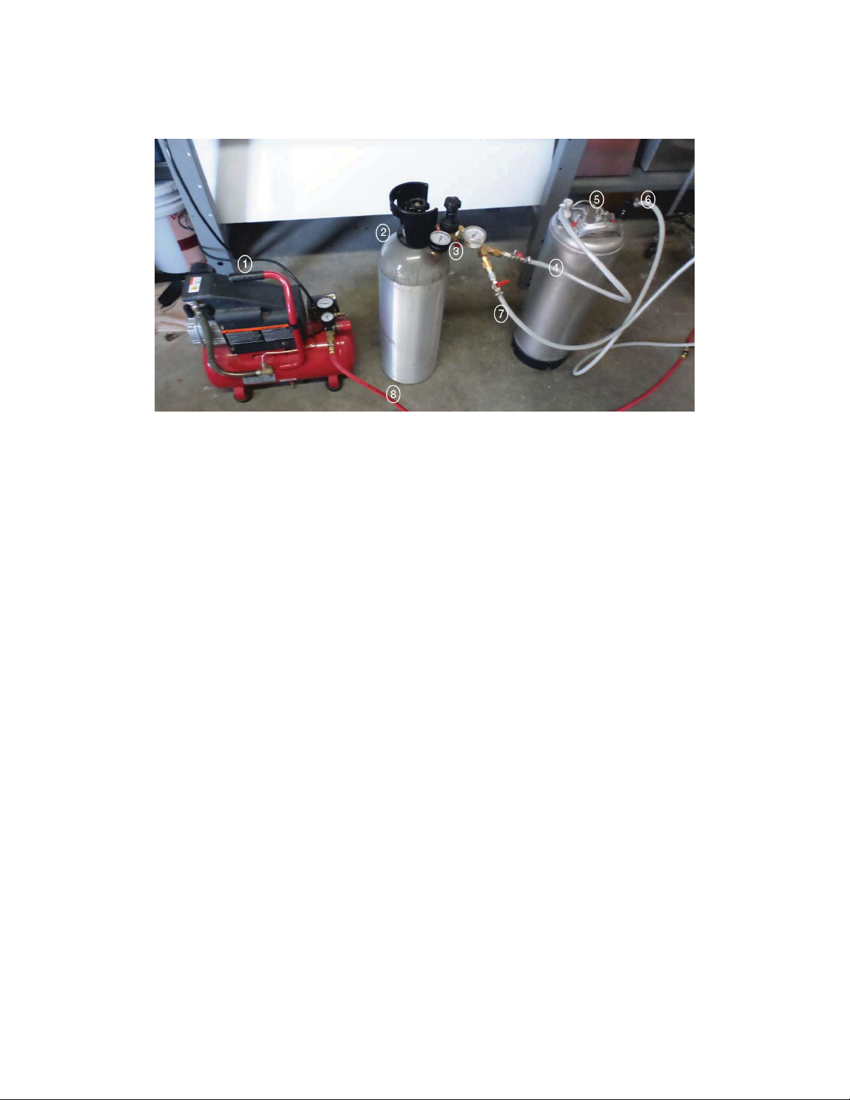
1. You will first want to unpack your filler from the
shipping box and spread the components out on a
large flat surface. Make sure that you also have the
following:
a. Pressurized CO2 tank with regulator and
connecting hosing (we recommend a wye as well,
see setup diagram for details).
b. Air compressor and 1/4" hosing
c. A small (.5 liter or so) catch container for
collecting vented liquid.
2. Place your filler on a flat surface where you plan to
bottle, ensuring that you have access to a standard
wall outlet or extension cord. Some type of surge
protection / power conditioner is recommended.
Place the liquid and CO2 tanks, as well as the air
compressor, nearby. Attach the support legs by
sliding the legs between the enclosure and the rubber
feet. The support legs should extend forward,
however if you extend them out the back you need to
clamp them to the flat surface.
3. Begin by plugging the provided power cord into your
machine, and then plug it into the wall. Now is a
good time to make sure that when you turn the
machine on, the green power switch lights up
4. Once you are sure that you have power to the
machine, flip all switches to their down or off
position. This includes all Fill Switches and all
Pressure Release Switches.
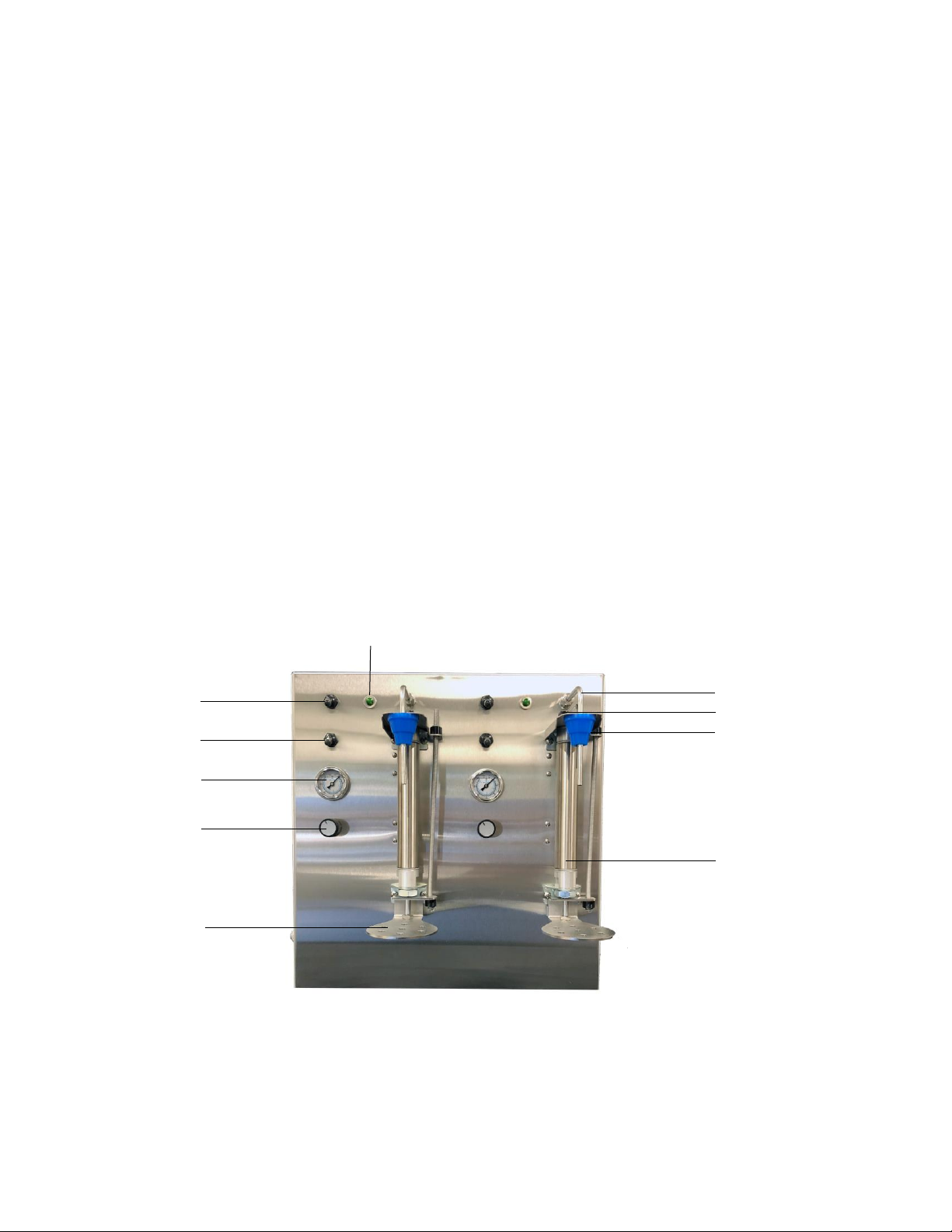
5. Plug the hose from your liquid container into the
port marked “Inlet” on the left side of the machine
using one of the provided 3/8” barbed fittings. See
“Adjusting Pressures” on page 11.
6. Plug one end of the provided 4’ x 1/4” hose into
the port marked “Vent” on the left side of the
machine, and place the other end into your catch
container.
7. Plug your air compressor into the port marked
“Air” on the left side of the machine using one of
the provided 1/4” barbed fittings. See “Adjusting
Pressures” on page 11.
8. Plug your CO2 tank into the port marked “CO2”
on the left side of the machine using one of the
provided 1/4” barbed fittings.
9. Once you are sure that all components are plugged
in correctly, you can open the valves on your tanks
and turn the air compressor on.
10. Turn on your machine by flipping the power
switch on the right side of your machine so that it
is lit up.
11. You are now ready to place a bottle on your
machine. While pressing down on the Bottle Foot
Rest, place a bottle on the Bottle Foot Rest and
allow the Bottle Foot Rest to lift the bottle towards
the stopper. The bottle does not seal yet, let it rest
in place near the stopper.
It is highly recommended that water be used during the initial set up procedure. Water allows you to familiarize
yourself with the filler by removing most variables related to your product, for ease of operation, and the
reduction of waste of your product.

265 Prado Road, Suite 1 | San Luis Obispo, CA 93401 | 805.541.0100 | xpressfill.com | [email protected]
11 | XpressFill Systems LLC
12. While the bottle is in place, turn on the Fill Switch to
the full up position. This begins the fill cycle: first
the bottle will purge for a few seconds, then the foot
will lift and the bottle will pressurize for a few
seconds. When the fill begins, the LED at the top of
the machine will light and the fluid solenoid will
open. If no liquid is flowing, adjust the bottle
interior pressure. Adjust the knob counter clockwise
(open) to the desired flow rate. If the flow is too
fast, you may adjust the bottle interior pressure knob
clockwise (close) to slow down the flow rate.
13. When the fluid has reached the desired level, the fill
light will go out and the fluid solenoid will close.
Place the fill switch to the center position which will
deactivate the fill light and solenoid circuit. In the
center position the Bottle Foot Rest is still engaged.
14. While the Bottle Foot Rest is still engaged, turn on
the Pressure Release Switch (UP). This allows the
bottle to depressurize. Place the fill and pressure
release switch to the full down position and the
Bottle Foot Rest will disengage, allowing you to
remove the bottle for capping. After removing the
bottle and before you place your next bottle on the
filler, turn off the Pressure Release Switch
(DOWN).
Congratulations, you have now filled your first bottle using the XF2500 Counter-Pressure Filling System!
Note: You can use the silicone surgical tubing included to fill from the bottom of the bottle or even halfway to the
bottom.
Adjusting Pressures
Should your filler pressure need to be adjusted, follow the steps listed below. Adjusting the pressure takes some
coordination, so it is recommended that you read through and understand all of the following steps before
attempting.
1. Follow steps 1-11 outlined in the setup instructions, setting the keg and CO2 pressures to your required values
rather than to the recommended settings.
2. Turn the bottle pressure adjustment knob counterclockwise until it becomes difficult to turn. Using too much
force may damage the valve.
3. Follow step 12-14 outlined in the setup instructions. Once the bottle foot rest is engaged, quickly switch to
turning the bottle pressure adjustment knob clockwise while watching the bottle pressure gauge until the desired
internal pressure is reached. This value should be roughly 5 psi lower than the keg pressure, but the optimal
value for your needs may vary.
4. Once you have reached the desired internal bottle pressure as indicated on the bottle pressure gauge, it is
recommended that you fill 1-3 test bottles to ensure the desired results have been achieved. Small adjustments
can be made using the same steps as above.
5. Repeat process on other spout.

If at any time you have issues with the setup or adjustment of your XF2500 bottle filling machine, or any other
questions about filling your product, please contact us at the number listed at the front of this manual. We are always
happy to assist you.
Excessive Foaming
Excessive foaming is usually the result to the keg pressure not being high enough, too high fluid temperature, or the
indicated pressure on the filler gauge is too low. The difference between the keg pressure and the counter pressure
indicated on the filler should be around 5 psi. The higher the pressure, the more CO2 will stay in solution.
Turning the Bottle Pressure Adjustment Knob clockwise will increase the bottle pressure and reduce foaming.
The higher the bottle pressure and lower the temperature, the more CO2 will stay in solution.
265 Prado Road, Suite 1 | San Luis Obispo, CA 93401 | 805.541.0100 | xpressfill.com | [email protected]
12 | XpressFill Systems LLC
5
Troubleshooting
Premature Shut Off
The XF2500 is a Level Fill Machine, meaning when liquid
touches a spout and probe, it will automatically shut off. If
moisture is allowed to collect between the spout and the probe,
the filler will shut off prematurely, stopping the fill or not
allowing the fill to begin at all, which is characterized by the
green LED fill indicator light to flash quickly and stay off as the
machine senses a full bottle is in place.
Dry the area between the spout and the probe with a clean
towel or use the compressor to air dry. Once completely dry, the
fill will resume.

6
Cleaning and Sanitizing
Cleaning your XpressFill is quick and easy, and is the single most important maintenance you can administer to
ensure long life and solid performance from your filler. Please use extreme caution when using any cleaning
product.
For general cleaning, we highly recommend a product called PBW by Five Star Chemicals. It is safe, fast, and
effective, and our customers have been happy with the results. To clean your XpressFill, begin by flushing your
filler with 2 gallons of plain warm (not boiling) water from a pressurized keg, which is pressurized with air. Follow
that with a 3-gallon mix of PBW cleaner, and let the PBW sit inside your filler for a few minutes in order to do its
cleaning job. Follow the cleaning with a sanitizer.
For sanitizing, we recommend Saniclean, from the same manufacturer. Saniclean has low foaming
characteristics, is highly effective, and completely food grade if diluted correctly per the manufacturer’s instructions.
Use the sanitizer with about 3 gallons of water, and follow the steps according to the manufacturer’s instructions.
After sanitizing, flush your filler with 2 gallons of warm water. Before storing your XpressFill filler, make sure you
get all water out of the flow path. Allow to run until pressurized keg with cleaning solution is empty and runs dry,
blowing the remaining water out of the filler vent.
See step-by-step instructions and diagrams on the following pages.
265 Prado Road, Suite 1 | San Luis Obispo, CA 93401 | 805.541.0100 | xpressfill.com | [email protected]
13 | XpressFill Systems LLC

1. Flip the Fill/Flush switch to flush mode (Rocker
switch located on left side of filler).
2. Place bottles under spouts.
3. Turn on the main power switch (Green rocker
switch located on right panel of the filler).
4. Turn on spout switch, full on position, all the way
up. Turn on the Pressure Release Switch (UP) to
allow flushing through the vent flow path.
5. Let solution fill the bottle completely and allow it to
run for a while after full.
6. Turn the spout switch to the middle position (stop
fill).
7. Turn on the spout switch again all the way up (This
runs the purge cycle again and allows the CO2
flow path to be cleaned as well). Repeat step 6 &7
a few times.
8. When satisfied with the cleaning process, put the
Fill/Flush switch back to Fill mode (DOWN).
9. Turn off the Fill Switch completely (DOWN). This
will allow you to remove the bottle and empty it of
the remaining cleaning solution. Also, turn off the
Pressure Release Switch (DOWN).
10. This is the end of part one of the two-part process
for cleaning your filler.
265 Prado Road, Suite 1 | San Luis Obispo, CA 93401 | 805.541.0100 | xpressfill.com | [email protected]
14 | XpressFill Systems LLC
Part One
Attach cleaning hoses as pictured below. Hosing and connectors are supplied in the accessory packet.

1. Turn on main power switch with bottles in place
(Green switch located right side).
2. Make sure the Pressure Release Switch is in the off
position (down).
3. Place bottles under spouts.
4. With gas line inserted, turn on spout switch and
allow gas to flow through the filling system.
5. Turn spout switch to middle position, and then back
up to full on position. Repeat this several times to
fully allow the purge path to ventilate.
6. Turn the release pressure knob at top of machine
clockwise to close valve about half way,
approximately ten turns.
7. Turn on the Pressure Release Switch for maximum
ventilation through the flow path.
8. When you are satisfied with the results, turn off
both the Fill Switches and Pressure Release
Switches (down) and then you can remove the
bottles.
9. Turn off the air/gas supply and remove all the hoses
10. Turn off the filler.
Note: Instead of using CO2, you can use an oil free air
compressor as well.
265 Prado Road, Suite 1 | San Luis Obispo, CA 93401 | 805.541.0100 | xpressfill.com | [email protected]
15 | XpressFill Systems LLC
Part Two
Attach cleaning hoses as pictured below. Hosing and connectors are supplied in the accessory packet.

265 Prado Road, Suite 1 | San Luis Obispo, CA 93401 | 805.541.0100 | xpressfill.com | [email protected]
16 | XpressFill Systems LLC
7
Additional Information
Collet Release Tool
Our fillers use “Push-to-Connect” type connectors which are standard in the beverage industry. Installation simply
requires pushing a hose into the fitting and pulling lightly to check that the connection is secure. Removal requires
using the collet release tool to firmly push the collet and remove the tube. A tool is included with the filler and can
be found inside the filler.
Push collet in with tool to remove hosing
Collet

265 Prado Road, Suite 1 | San Luis Obispo, CA 93401 | 805.541.0100 | xpressfill.com | [email protected]
17 | XpressFill Systems LLC
Delay-Timer Adjustment
Spare Fuse
There is a spare fuse in the power cord receptacle. Unplug the machine and set a screwdriver on the notch (do not
remove screws) and pop the spare fuse holder toward you, then replace the fuse. XpressFill Part No. 200002 –
Bussmann Series by Eaton, Model BK/GDB-2A, 250V Fast Acting, 5mm x 20mm.
The exposed fuse in the clip is the active fuse. The fuse stored in the box holder is the spare.
Each spout has two delay timers and
easily accessible with the filler tipped
forward to lay on the spouts and foot
brackets.
Both timers are activated when the spout
is put in “Fill Mode.”
The small blue dial is the time adjustment
from .1 second to 10 seconds.
The top timer controls the lift of the foot,
lifting the bottle against the stopper, after
the desired purge time.
The lower timer operates the total CO2
output time, this should always be
adjusted for a bit longer period than the
top timer to allow for the bottle to
pressurize after purging.

265 Prado Road, Suite 1 | San Luis Obispo, CA 93401 | 805.541.0100 | xpressfill.com | [email protected]
18 | XpressFill Systems LLC
Fluid Solenoid Valve Deep-Cleaning Instructions
Note: This maintenance is needed only when the filler is not performing properly.
Remove the solenoid valve from the filler. Use the
release tool provided to disconnect the push-to-connect
fittings. If you disconnect the two wires, it does not
matter which wire goes back into which terminal.
Loosen the hex nut at the top of the coil assembly.
Unscrew the base from the coil assembly. Use a
screwdriver as needed. Remove the center shaft. Note
and keep track of the flat O-ring. A pair of pliers may
be needed to grip the metal shaft to “crack” open for
unscrewing the shaft.
Now clean out all openings inside and outside of the
solenoid valve, removing any particulates and
stickiness that may have accumulated.
Reassemble and replace in the filler.
The white plastic body is marked #1 for output and
#2 for input. The valve may leak if installed back-
wards.

265 Prado Road, Suite 1 | San Luis Obispo, CA 93401 | 805.541.0100 | xpressfill.com | [email protected]
19 | XpressFill Systems LLC
CO2 Purge Solenoid Valve Deep-Cleaning Instructions
Remove the solenoid valve from the filler. Use the
release tool provided to disconnect the push-to-connect
fittings from the tubes.
Slide off the clip from the top of the coil assembly.
Remove the coil assembly off the center shaft. Unscrew
the shaft from the stainless steel base. It is not necessary
to unscrew the tubing adaptors from the stainless steel
base.
Now rinse out all the openings inside and outside of the
solenoid valve, removing any particulates and
stickiness that may have accumulated.
Reassemble and replace in the filler.
Stainless steel valve body is marked #1 for input,
#2 for output. Note: Valve may leak if installed
backwards.
Note: This maintenance is needed only when the filler is not performing properly.

265 Prado Road, Suite 1 | San Luis Obispo, CA 93401 | 805.541.0100 | xpressfill.com | [email protected]
20 | XpressFill Systems LLC
Accessory Kit
Part Number Key
300042 –1/4”ID Polyethylene hosing
300081 –3/8”Hose barb connector
300083 –3/8”x3/8”x1/4”Reducing tee
300084 –3/8”x1/4”Reducing elbow
300090 –3/16”ID Surgical tubing
300091 –3/8”Union connector
900003 –1/4”Hose barb connector
Other manuals for XF2500
1
Table of contents
Popular Beverage Dispenser manuals by other brands

Perlick
Perlick HP15TS-3 A Series installation manual

Cornelius
Cornelius Agitator Motor 569000207 installation manual

Curtis
Curtis CFB1 Service manual

Flavor Burst
Flavor Burst TS 44SS manual

Grindmaster
Grindmaster Crathco MG236-2B Operation and instruction manual

Klarstein
Klarstein Hazlehov Sixtett manual

Bunn
Bunn HC-1 OPERATING & SERVICE MANUAL

Crathco
Crathco PIC 4 Service manual

Hamilton Beach
Hamilton Beach 40516R manual

INTERNATIONAL CARBONIC
INTERNATIONAL CARBONIC SPACE CADET SCR Installation and service manual

ELME
ELME BIG BIZ Use and maintenance manual

MICROMATIC
MICROMATIC PRO-LINE WINE MDD58W Series Installation, use & maintenance guide