Operation Manual 20
Labels
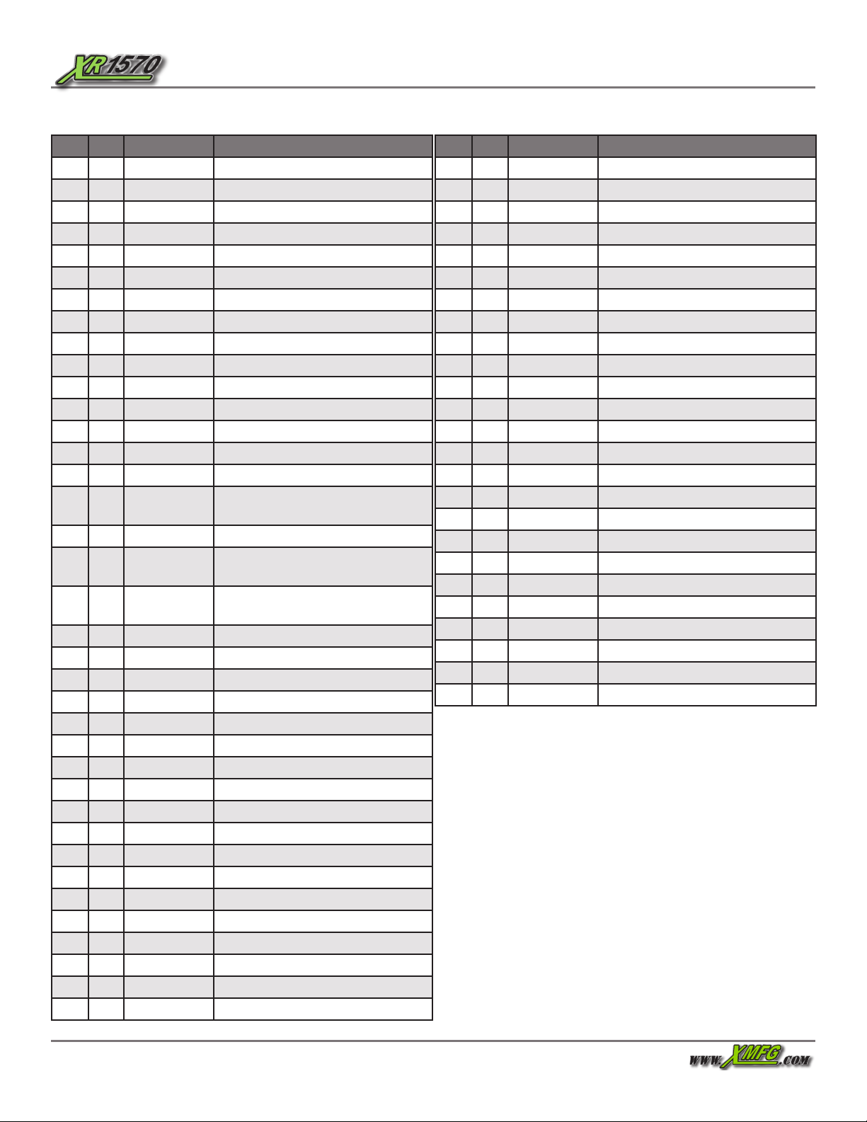
Item Qty Part No. Description
11 18008-000 Data Plate
21 18004-060 Dash Overlay
31 18010-001 Caution, Slip/Trip Hazard
41 18011-001 Caution, Engine Damage Hazard
51 18013-001 Diesel Only (Tier 4)
61 18014-001 Check Engine Oil (Tier 4)
71 18015-001 Check/Fill Coolant
81 18016-001 Caution, Burn Hazard
92 18017-001 Danger, Crushing Hazard
10 8 18018-001 Danger, Electrocution Hazard
11 1 18018-002 Danger, Electrocution Hazard
12 3 18019-001 Danger, Crushing Hazard
13 1 18020-001 Warning, Tip-Over Hazard
14 1 18021-001 Danger, Crushing Hazard
15 1 18022-001 Warning, Tip Over Hazard
16 1 18023-001 Warning, Welding and Modication
Hazard
17 1 18025-001 Warning, Falling Hazard
18 1 18026-001 Warning, Unrestrained Operator
Hazard
19 1 18027-001 Danger, Rotating Equipment
Hazard
20 1 18031-001 Warning, Safe Operation Checklist
21 1 18032-001 Warning, Improper Use Hazard
22 1 18033-000 Auxiliary Handle Control
23 1 18034-000 Boom Handle Control
24 1 18039-000 Boom Angle Indicator
25 6 18041-001 Warning, Pinch Point Hazard
26 3 18042-000 Xtreme logo (chassis)
27 2 18066-001 Caution, Crushing Hazard
28 1 18067-100 Frame Sway Handle
29 1 18334-001 Handle Auxiliary Controls
30 1 18069-000 Hydraulic Tank Fluid Level
31 1 18082-001 Warning, Injection Hazard
32 2 18083-001 Warning, Explosion Hazard
33 1 18086-001 Hydraulic Fluid, Use Dexron III
34 4 18090-001 Warning, Tip Over Hazard
35 2 18300-001 Warning, Falling Hazard
36 2 18312-000 Warning, Falling Hazard
37 4 18315-000 Tie Down Point
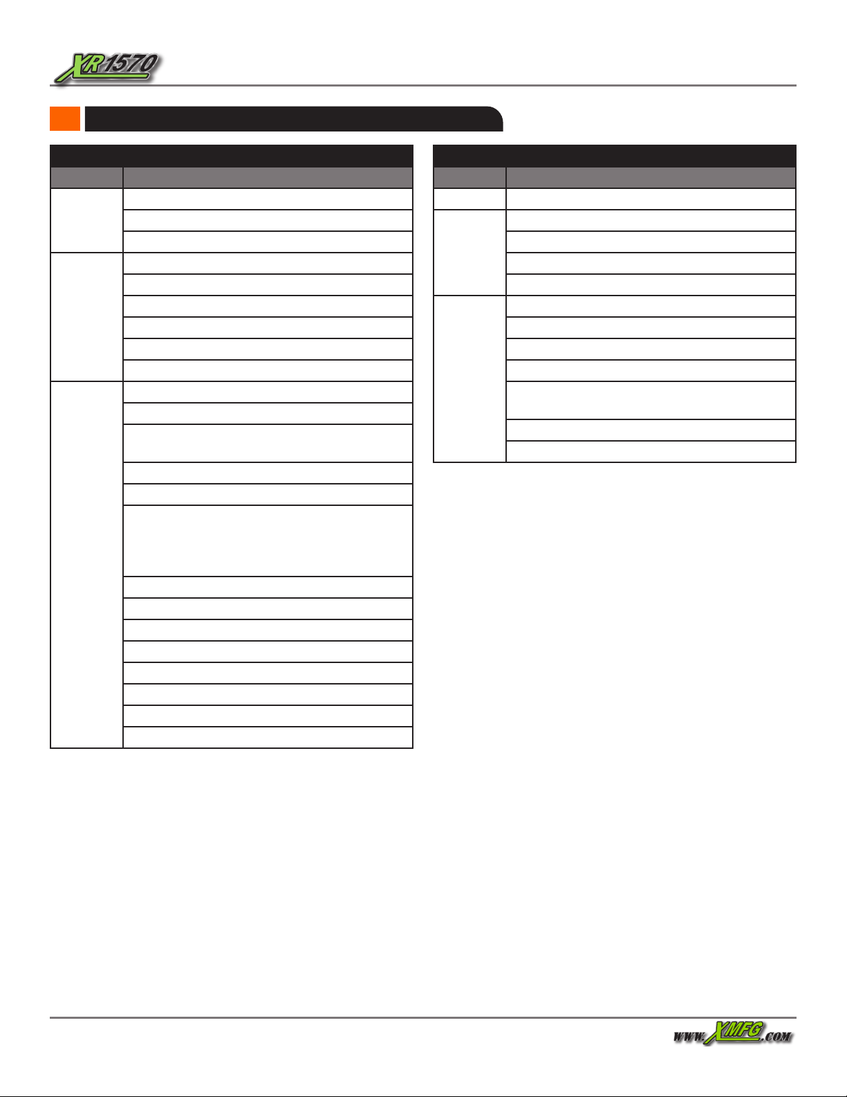
Table 1. Labels
Item Qty Part No. Description
38 1 18043-000 Xtreme logo
39 1 18044-000 Xtreme X
40 1 18046-000 Boom Swoosh Left Front
41 1 18047-000 Boom Swoosh Left Rear
42 1 18048-000 Boom Swoosh Right Front
43 1 18049-000 Boom Swoosh Right Rear
44 2 18472-000 XR1570
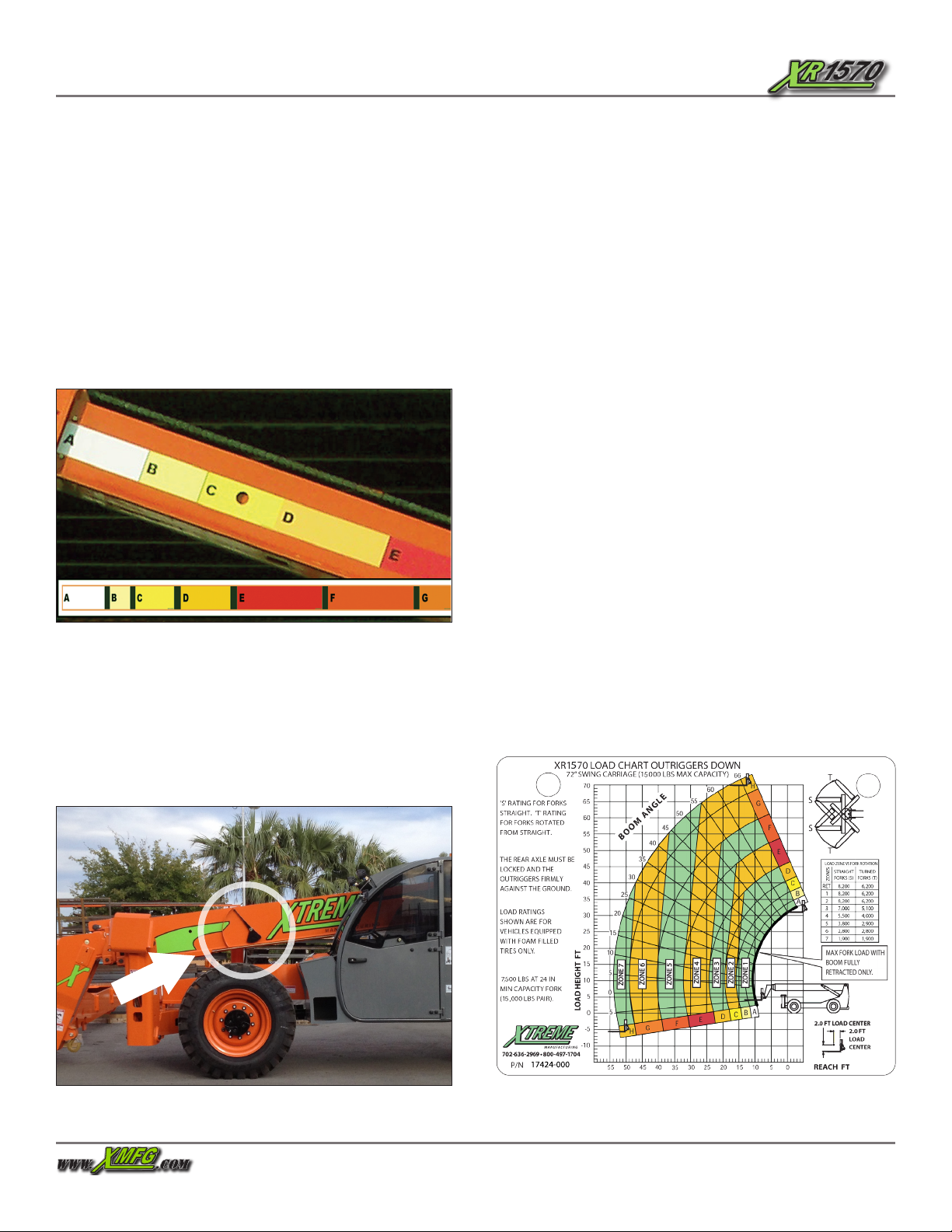
45 1 18056-000 Boom Lettering A-B-C-D
46 1 18057-000 Boom Lettering E-F
47 1 18058-000 Boom Lettering G-H
48 1 18311-003 Boom Hook 15k
49 1 18331-000 Caution, Adjustable Carriage
50 1 18332-000 Warning, Tow Capacity
51 1 18307-001 Warning, Falling Hazard
52 1 18306-001 Danger, Crushing Hazard
53 1 18306-000 Danger, Crushing Hazard
54 1 18241-015 Label, XR1570 CG Lifting Points
55 1 18413-000 Fill DEF Tank
56 1 18409-000 “DEF ONLY” Label
57 1 18412-000 Caution, Equipment Damage
58 2 18241-016 Decal, CG & Lift Points, XR1570
~1 17423-000 Load Chart,1570 Std. Carr. OR up
~1 17424-000 Load Chart,1570 Std. Carr OR down
~1 17423-001 Load Chart 1570 Swing Carr OR up
~1 17424-001 Load Chart 1570 Swing Carr OR dn.