Yacht Devices YDTA-04N User manual

User Manual
Tank Adapter YDTA-04
also covers models
YDTA-04N
Firmware version
1.00
2021

© 2021 Yacht Devices Ltd. Document YDTA04-001.February 15, 2021. Web: http://www.yachtd.com/
Yacht Devices Tank Adapter YDTA-04 is certied by the National Marine
Electronics Association.
NMEA 2000® is a registered trademark of the National Marine Electronics
Association. SeaTalk NG is a registered trademark of Raymarine UK Limited.
Garmin® is a registered trademark of Garmin Ltd.

Contents
Introduction 4
Warranty and Technical Support 5
I. Product Specication 6
II. Installation and Connection of Device 8
III. LED Signals 15
IV. Device Conguration and Settings 16
V. Conguration with Presets (Button) 18
VI. Conguration with Installation Description Strings 20
VII. Digital Switching 27
VIII. Firmware Updates 32
Appendix А. Troubleshooting 34
Appendix B. NMEA 2000 Messages Supported by Device 36
Appendix Appendix C. Digital Switching with NMEA 2000 Bridge 38
Package Contents
Device 1 pc.
Screws 2 pc.
This Manual 1 pcs.
Paperclip for reset 1 pcs.
NMEA 2000 Drop Cable not supplied

— 4 —
Introduction
The NMEA 2000 Tank Adapter YDTA-04 (hereinafter Adapter or Device) allows you to connect an existing
resistive or voltage-output type uid level sensor installed on a tank and display the uid level on NMEA
2000 devices, including chart plotters and instrumental displays.
The Adapter can be congured to report one of the 15 uid types dened in the NMEA 2000 standard,
including Diesel Fuel, Gasoline Fuel, Oil, Fresh Water, Waste Water, Black Water (Sewage), or Live Well.
The Device can be used with European (10 to 180 Ohm range), American (240 to 33 Ohm range) or Japanese
(0 to 310 Ohm range) standard uid level sensors as well as with any nonstandard sensors with maximum
resistance less than 400 Ohm. The Device can also be used with uid level sensors, which output an analog
voltage signal in the range of 0 to 16 Volts.
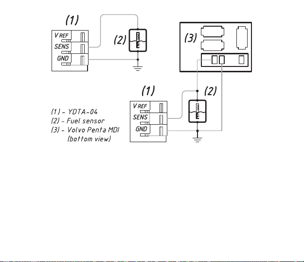
The Adapter can be installed as a standalone measuring device, in parallel with an existing analog gauge
(2-coils and 1-coils gauges are supported), or in parallel with a Volvo Penta engine’s MDI (Mechanical Diesel
Interface) box. The four measuring channels of the Device may have individual settings. Fluid tank level
sensor readings can be calibrated with 12 calibration points to get accurate readings on tanks of any shape.
The Adaptor can switch the load channels of NMEA 2000 digital switching equipment on or o. Up to eight
dierent conditions for each measuring channel can be used.
Firmware updates are available only with Yacht Devices gateways (Wi-Fi, USB or Ethernet), see Section
VIII for details.
The Device is powered from the NMEA 2000 network and provides high voltage galvanic isolation between
NMEA 2000 and sensor inputs.
We thank you for purchasing our Devices and wish you happy voyages!
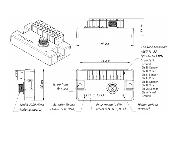
The Device is equipped with a hidden button that allows switching among 15 conguration
presets (see Section V). However, for advanced conguration (calibration curves, digital
switching functions, connection in parallel with analog gauges, using voltage sensors)
the NMEA 2000 PC gateway (from any manufacturer) or MFD which allows editing of
installation description strings (see Section VI) is required.

— 5 —
Warranty and Technical Support
1. The Device warranty is valid for two years from the date of purchase. If a Device was purchased
in a retail store, the sale receipt may be requested when applying for a warranty claim.
2. The Device warranty is terminated in case of violation of the instructions in this Manual, case
integrity breach, or repair or modication of the Device without the manufacturer’s written
permission.
3. If a warranty request is accepted, the defective Device must be sent to the manufacturer.
4. The warranty liabilities include repair and replacement of the goods and do not include
the cost of equipment installation and conguration, as well as shipping of the defective Device
to the manufacturer.
5. Responsibility of the manufacturer in case of any damage as a consequence of the Device’s operation
or installation is limited to the Device cost.
6. The manufacturer is not responsible for any errors and inaccuracies in guides and instructions
of other companies.
7. The Device requires no maintenance. The Device’s case is non-dismountable.
8. In the event of a failure, please refer to Appendix A before contacting technical support.
9. The manufacturer accepts applications under warranty and provides technical support only
via e-mail or from authorized dealers.
10. The contact details of the manufacturer and a list of the authorized dealers are published on our
website: http://www.yachtd.com/

— 6 —
I. Product Specification
Figure 1. Drawing of Tank Adapter YDTA-04N

— 7 —
Device parameter Value Unit
Supply voltage (from NMEA 2000 network) 7..16 V
Current consumption (from NMEA 2000 network), avg./max 51 / 62 mA
Load Equivalency Number 2 LEN
Galvanic isolation between NMEA 2000 interface and sensor inputs 2500 V
RMS
Number of measurement channels 4
Maximum voltage on sensor and gauge reference voltage inputs 16 V
Voltage output sensor supported range 0..16 V
Fluid level sensors resistance range 0..400 Ohm
Analog gauge coils resistance range 0..10 000 Ohm
Sensor resistance/voltage measurement accuracy ±1 %
Device case dimensions (LxWxH) 85 x 46 x 29 mm
Weight 50 g
Operating temperature range -20..55 °С
Yacht Devices Ltd declares that this product is compliant with the essential requirements of EMC
directive 2004/108/EC.
Dispose of this product in accordance with the WEEE Directive. Do not dispose of electronic refuse
with domestic or industrial waste.

— 8 —
II. Installation and Connection of Device
All connections should be made when the power is cut o at the circuit breaker. This will
protect against accidental short circuits during installation.
Connect the Device to the tank level sensor before making the connection to the NMEA 2000
network. This will protect against accidental sparks which can be hazardous when working
with fuel tanks.
The Device requires no maintenance. When deciding where to install the Device, choose a dry mounting
location. Despite the fact that the Device’s case is waterproof, its wire terminals are open, and seawater can
cause corrosion or a short circuit. Do not place the Device where it can be ooded by water, get wet in rain
or be sprayed by water.
The Device has two mount holes (see Section I), 4 mm in diameter. Use the supplied screws to x the Device
on a at surface. The orientation is not important. However, when the holes of wire terminals are pointing
down, they are better protected from occasional spray.
1. Tank level sensor connection
The Device has four measurement channels (A, B, C, D) which share a common electrical ground (two
Ground wire terminals, labeled as GND, are connected inside and galvanically isolated from the NMEA
2000 ground).
The channel contains two individual inputs: a sensor input (labeled as SENS), which should be connected
to the tank sensor, and a voltage reference input (labeled as VREF), used in parallel connection with analog
gauges.
Dierent channels may have dierent connection schemes and settings. In this section, we will show an
example of the possible connections for one channel, and channel name will be omitted on the drawings.

— 9 —
1.1 Standalone sensor connection
If you do not have a gauge connected to your tank level sensor (e. g. you have installed the sensor yourself),
you should connect only two wires to the Adapter: from SENS to the sensor «Signal» or «+» output and
from GND to sensor «Ground» or «−». The VREF input should be left unconnected. The CONNECTION
setting for the channel should be set to RESISTIVE (refer to Section VI); this is the factory setting.
1.2 Sensor for Volvo engines with MDI unit
If the fuel tank level sensor is connected to the Volvo engine MDI (Mechanical Diesel Interface) unit, you
can connect the Adapter in parallel with the MDI unit «Fuel level» input: the SENS terminal should be
connected to MDI pin 11 (or the sensor’s Green wire) and GND terminal to the MDI pin 12 (or sensor
Green/Black wire). VREF terminal should be left unconnected. You should also congure the channel and
set the CONNECTION setting to MDI (refer to Section VI).

— 10 —
Figure 1. Standalone sensor connection (left) and connection in parallel with Volvo MDI unit (right)
1.3 Connection in parallel with an existing analog gauge
An analog gauge connected to your tank level sensor can be of two types: with one measuring coil (the gauge
has only two terminals) or with two measuring coils (the gauge has three terminals).
You may have a «combined» gauge equipped with several buttons (see Figure 2), one of which activates
measurement of the tank level. The Adapter detects whether the button pressed or not, and this does not
aect the measurement results.

— 11 —
1.3.1 Connection to a 1-coil gauge
If the gauge has one coil, the VREF input should be connected to the gauge’s power terminal (up to 16
Volts), the SENS terminal to the gauge «Signal» input, and the GND terminal to the fuel sensor’s ground
terminal. If you have the «combined» gauge, connect the SENS terminal to the uid level sensor output (or
«+») before the button. You should also congure the channel and set the CONNECTION setting to 1COIL
(refer to Section VI.3.1).
(1) — YDTA-04, (2) — Gauge, (3) — Fuel Sensor, (4) — Optional Button, (5) and (6) — Parallel Sensors
(optional)
Figure 2. Connection in parallel with an existing 1-coil analog gauge

— 12 —
1.3.2 Connection to a 2-coil gauge
If the gauge has two coils, the VREF terminal should be connected to the gauge’s power terminal (up to 16
Volts), the SENS terminal to the gauge’s «Signal» input (or to the uid level sensor’s «Signal» wire after the
measurement activation button, see Figure 3), and the GND terminal to the gauge’s «Ground» terminal.
You should also congure the channel and set the CONNECTION setting to 2COIL for connection scheme
shown on the right part of Figure 3 (or if your gauge has no buttons) or to 2COIL_VCC for connection
scheme shown on the left part of Figure 3 (see Section VI.3.1).
(1) — YDTA-04, (2) — Gauge, (3) — Fuel Sensor, (4) — Optional Button, (5) and (6) — Parallel Sensors
(optional)
Figure 3. Connection in parallel with an existing 2-coil analog gauge

— 13 —
1.3.3 Neutralize gauge eects
When using an Adapter with an existing gauge, you will need to measure its coil resistance values with an
ohmmeter or multimeter and set the measured values to the conguration with the command YD:OHMS_
GAUGE (refer to Sections VI.3.3).
To make an accurate measurement, you will need to warm up your gauge: turn it on and let it operate for
approx. 15 minutes. When you are ready, promptly disconnect the gauge and measure the COIL 1 resistance
— between the gauge reference voltage source (+12V) input and sensor «signal» input. For a 2-coil gauge,
you should also measure the COIL 2 resistance — between the gauge «signal» input and gauge «ground»
input. To increase accuracy, make several measurements and take the average value.
1.4 Connection to a voltage-output sensor
Check your voltage-output sensor specications, it should support output of an analog voltage signal in the
range of 0 – 16 Volts. Congure the sensor to activate this output mode if necessary. Connect the SENS
terminal to the «Voltage» output of the sensor and the GND terminal to «Ground» or «−» of the sensor.
If you have a sensor with an additional reference voltage output, connect it with VREF terminal, this will
increase the measurement accuracy. Otherwise, the VREF terminal should be left unconnected. You should
also congure the channel and set the CONNECTION setting to VOLTAGE and congure voltage settings
(refer to Section VI.3).
1.5 Parasitic sensor wire resistance compensation
If you connect the Device directly to a uid level sensor, but the wire which connects the uid level sensor
to a «Signal» input of an analog gauge is too long, it may add an additional xed value to the gauge coil
resistance, which can cause a persistent measurement error. If the total sensor wire length is greater
than 5 meters, it is recommended to measure the resistance with an ohmmeter or multimeter and set the
measured value in the channel’s conguration parameter OHMS_WIRES (refer to Section VI.3.4).

— 14 —
2. Connection to NMEA 2000
The Device should be connected to the NMEA 2000 network backbone with a NMEA 2000 drop cable (not
supplied with the Device). The Device is equipped with a DeviceNet Micro Male connector. For NMEA
2000 networks with other connector types, you will need an appropriate adapter cable.
Before connecting the Device, turn o the bus power supply. If you have any questions regarding the use of
connecting cables, terminators or connectors, please refer to the following documents:
•
• SeaTalk NG Reference Manual (81300-1) for Raymarine networks.
After connecting the Device, close the lock on the connector to ensure its water resistance and reliability.
The Device is powered from the NMEA 2000 network and has LEDs, which ash red or green. After the
NMEA 2000 network power is turned on, the status LED (labeled “N2K”) should produce one long and
three short green ashes. If this does not happen, refer to Appendix A.
You can also check the NMEA 2000 connection and rmware version from a chart plotter. The Device
information including the rmware version is displayed in the list of NMEA 2000 devices (SeaTalk NG,
SimNet, Furuno CAN) or in the common list of external devices on the chart plotter. Usually, access to this
list is in the «Diagnostics», «External Interfaces» or the «External devices» menu entry of the chart plotter.
Technical Reference for Garmin NMEA 2000 Products (190-00891-00)
for standard NMEA 2000 networks;

— 15 —
III. LED Signals
The Devices incorporates a bi-color Device status LED (labeled “N2K”) and four channel status LEDs. Their
locations are pictured in Section I on Figure 1.
1. Powering on
One 1-second long GREEN ash of the status LED after powering on the Tank Adapter conrms successful
initialization. Further, three successive GREEN ashes of the status LED indicate that the Device is
successfully connected to the NMEA 2000 network.
Constant RED ashes (one second on, one o) of the status LED indicate a failure to obtain an NMEA 2000
network address.
2. Normal operation
During normal operation, the Device’s status LED blinks every 2.5 seconds. GREEN ashes mean that all
messages were sent by the Device without errors, RED indicates a problem on the NMEA 2000 backbone.
Channel LEDs do not ash if no problems with the channel are found, otherwise channel LED ashes RED
every 2.5 seconds to indicate the problem with sensor or conguration. If you turned on the Device without
connected sensors, it is normal that all channel LEDs ash RED.
If you have unused measurement channels on the Device, you can turn them o (see Section VI.3.1).
3. Signals during conguration with button
The LEDs' behavior during conguration with hidden button is described in the Section V.
4. Signals during rmware update
The LEDs' behavior during rmware update is described in the Section VIII.

— 16 —
IV. Device Configuration and Settings
The Device can be congured by two dierent methods:
1. By selecting one of predened conguration presets using the hidden button. This method is limited
by standard resistive sensors and connection with Volvo Penta MDI units, and does not allow
conguration of the calibration curves, digital switching functions, setup of the connection in parallel
with analog gauges, or use of the voltage sensors.
2. With a special set of commands which can be entered into the installation description eld of the
Device using PC software like CAN Log Viewer developed by our company, ActiSense NMEA Reader
or Maretron N2KAnayzer. This method is very simple and may be supported in some chart plotter
models.
All settings congured with the second method will be lost after switching the preset with the rst method.
When you selected the preset with the rst method and alter any setting with the second method, the actual
preset number will be changed to 15 (user-dened preset, see the Section V).
The most important settings are:
A. Tank number. Also known as NMEA 2000 data instance. The rst tank should have the number 0.
Numbering is individual for each uid type, e.g. the rst diesel tank and rst fresh water tank both
have number 0.
B. Fluid type. The Devices support all uid types available in NMEA 2000: diesel, fresh water, waste,
live well, oil, sewage (black water), and gasoline. These types have numbers 0 - 6. You can also use
numbers 7 – 15, which are reserved in NMEA 2000 and have no dened meaning. Note that chart
plotters usually support only a few of them, and even gasoline tanks are not supported in many chart
plotters.
Conguration of the Device should not be performed at sea.

— 17 —
C. Connection type. The Adapter support multiple sensor’s types (resistive, voltage, Volvo Penta MDI)
and dierent connection schemes (standalone, in parallel with 1-coil or 2-coil gauges). In case of a
parallel connection, you should measure the resistance of a gauge’s coils and specify it in the Device’s
settings; this is possible with the second conguration method only.
With the factory settings, Device channels are congured for using with USA resistive sensors (240
Ohms when empty, 33 Ohms when full). Tank numbers for channels A, B, C, and D, are 0, 1, 2, and 3
correspondingly. Fluid type is set to diesel for all channels. These settings are correspond to conguration
preset #1.
Aside from the connection type and uid type, the following settings (can be congured with the second
method only) can improve the accuracy of readings:
D. Calibration. Resistive fuel level sensors do not take the shape of the fuel tank into account, therefore,
the readings usually have substantial error. The same issue is applicable to the voltage-output sensors
which do not have an internal calibration mechanism or do have a non-linear output. The Adapter
allows setting a 12-point calibration curve for each channel.
E. Capacity. If the capacity for a tank is specied, your MFD will allow display of a tank’s level not only
in percent, but in liters or gallons also. In factory settings, capacity for all tanks is set to UNKNOWN.
F. Damping. With factory settings, the Adapter transmits the average value measured in last 3 seconds.
This can be too small for rough sea conditions and too big for some applications (e.g., controlling of
live well pump or fuel pump with digital switching).
We recommend learning about both conguration methods before conguring the Device.

— 18 —
V. Configuration with Presets (Button)
Press the hidden button (see Figure 1 in Section I) with the paper clip supplied with the Device. The status
LED of the Device will constantly shine RED and channel LEDs will display the preset number in binary (A
is the lowest bit, D is highest, see the Table 1 below) when the hidden button is pressed.
Wait 2-3 seconds and the LEDs lights will start flashing. Release the button to enter the programming mode.
Otherwise, when LEDs will stop blinking 2-3 seconds later, release the button to return to normal operation.
In the programming mode, each press of the button increases the preset number. After preset 15 (all channel
LEDs are on, binary 1111), the preset number will be reset to 1 (only the channel’s A LED is on, binary 0001).
Settings of the active preset will be applied immediately, and you can check the configuration on MFD screen
or instrument displays (are numbers correct or not).
To save the selected preset, press the button and hold it for 3 seconds until all LEDs start blinking. After
saving, the Device will return to normal operation mode.
To return to normal operation mode without saving, do not press the button for 30 seconds, and the Device
will restore the configuration that was active before entering the programming mode, and return to normal
operation.
Table 1. Conguration presets
Preset (DCBA) Description
1 (0001) Factory settings. Channels ABCD are congured to USA (240..33 Ohm) resistive
sensors of fuel tanks with numbers 0..3.
2 (0010) Channels ABCD are congured to EUR (10..180 Ohm) resistive sensors of fuel tanks
with numbers 0..3.
3 (0011) Channels ABCD are congured to JAP (0..310 Ohm) resistive sensors of fuel tanks
with numbers 0..3.

— 19 —
4 (0100) Channels AB are connected to fuel tanks (0 and 1), and CD to water tanks (0 and 1).
Sensors are of resistive type (USA, 240..33 Ohm).
5 (0101) Channels AB are connected to fuel tanks (0 and 1), and CD to water tanks (0 and 1).
Sensors are of resistive type (EUR, 10..180 Ohm).
6 (0110) A – fuel tank (0), B – waste tank (0), CD – fresh water (0 and 1). Sensors are of
resistive type (USA, 240..33 Ohm).
7 (0111) A – fuel tank (0), B – waste tank (0), CD – fresh water (0 and 1). Sensors are of
resistive type (EUR, 10..180 Ohm).
8 (1000) A – MDI unit (fuel tank 0), B – waste tank (0), CD – fresh water (0 and 1). Sensors are
of resistive type (USA, 240..33 Ohm).
9 (1001) A – MDI unit (fuel tank 0), B – waste tank (0), CD – fresh water (0 and 1). Sensors are
of resistive type (EUR, 10..180 Ohm).
10 (1010) AB – MDI units (fuel tanks 0 and 1), CD – fresh water (0 and 1). Sensors are of
resistive type (USA, 240..33 Ohm).
11 (1011) AB – MDI units (fuel tanks 0 and 1), CD – fresh water (0 and 1). Sensors are of
resistive type (EUR, 10..180 Ohm).
12 (1100) Reserved for future use. In the 1.00 rmware is identical to preset 1 but with
tank numbers 4-7.
13 (1101) Reserved for future use. In the 1.00 rmware is identical to preset 2 but with
tank numbers 4-7.
14 (1110) Reserved for future use. In the 1.00 rmware is identical to preset 3 but with
tank numbers 4-7.
15 (1111) User dened. Settings was congured or altered with installation description
strings (see Section VI).
Table 1 continued

— 20 —
VI. Configuration with Installation Description Strings
Installation description strings are stored in the Device’s memory and are usually written by installers to
specify the device location or to leave notes or contact information. They can be set with a PC software
and a hardware gateway to the NMEA 2000 network. Some models of chart plotters also allow editing of
installation description strings. Please refer to your software or chart plotter documentation for details.
Figure 1. Programming with CAN Log Viewer
Table of contents