Yaesu FC-50 User manual

1
Automatic Antenna Tuner FC-50
Installation Instructions
Thank you for your purchase of the model FC-50 Automatic Antenna Tuner. The FC-50 is designed specically for
the FT-891 HF/VHF Transceiver. A cooling fan is incorporated in the tuner to ensure thermal stability of the critical
matching elements mounted within the compact case.
The FC-50 Automatic Antenna Tuner responds to control commands from the FT-891 Transceiver, providing
microprocessor-based impedance matching on the 160 through 6 meter Amateur bands. On the HF bands the
impedance matching range is from 16 Ω to 150 Ω (up to 3:1 SWR) and on the 50 MHz band the impedance
matching range is from 25 Ω to 100 Ω (up to 2:1 SWR). Accordingly, the FC-50 should not be expected to match “long
wire” type antennas unless specic design steps are taken to ensure that the impedance presented to the FC-50 is
within these specications.
Please refer to the FT-891 Operating Manual for operating instructions.
The FC-50 tuner can be activated during receive (refer to "Activate the tuner during receive" on page three of these
instructions).
Front & Rear Panel Information
The ventilator
air intake ducts
are for cooling.
Do not place any
objects that restrict
air flow near the
ducts.
Connect the Control Cable
from the FT-891 to this
miniature DIN connector.
Use this “M” type
( “SO-239” ) jack
for connection of
the coaxial cable
from the FT-891.
This “M” type
(“SO-239”) coaxial
jack accommo-
dates the antenna
input for the FC-50.
The ventilator air intake ducts
are for cooling. Do not place any
objects that restrict air flow near
the ducts.
Front Side Rear Side
Installation to the FT-891
1. Referring to the gure below, remove the four feet and reattach the feet on the bottom of the transceiver with
the supplied screws A (M3x8B) (use a screwdriver).
Do not attach any parts other than the supplied mounting parts .
2. Remove the four rubber caps on the top case of the FC-50.
3. Slide FT-891 with the supplied feet toward the rear of the FC-50, into the slots from which the rubber caps were
removed in step (2) above.
Replace the feet on the
bottom of the transceiver
with the supplied feet.
Slide FT-891
forward into the
slots of FC-50.
Attach the supplied
feet.
A
When installing the FC-50 and the FT-891 separately, purchase an additional Mobile Mounting
Bracket(MMB-82), and mount both units securely.

2
4. Attach the joining plates on both sides of the FC-50 and the FT-891 respectively with the supplied screws (use
a screwdriver).
When operating the FC-50 attached to the FT-891 without the Mobile Mounting Bracket, attach them with the
supplied screws B (M4x6B).
When operating the FC-50 attached to the FT-891 with the Mobile Mounting Bracket (MMB-82), attach the plates and the
bracket with the supplied screws C (M4x10B) and the Cushion Adhesive tapes.
Attachment with the Mobile
Mounting Brackets (MMB-82)
Normal Attachment
B
Mount the bracket
using the the
bracket screws,
nuts and washers, into
the screw holes at the
four corners of the Mobile
Bracket(MMB-82), to
secure it during intense
vibration.
C
Stick the supplied
Cushion Adhesive
Tape on the upper
edge of the joint-plate.
Interconnections to the FT-891
Turn the power OFF before connecting the cables to
the FC-50.
Do not connect or disconnect the control cable or
the coaxial cable with wet hands. Do not connect or
disconnect the control cable or the coaxial cable while
transmitting, this may cause an electric shock or injury.
Do not place any objects near the FC-50 ventilator ducts.
CONTROL
ANT
ANT
TUN/LIN
TRX
Supplied Control Cable
To HF/50 MHz Antenna
Supplied Coaxial Cable

3
Activate the tuner during receive
By conguring the internal DIP switches, the RF signal path may be changed to enable the tuner on both receive
and transmit.
Remove case
1. Turn the FT-891 POWER switch OFF and Remove all cables that are connected to the FC-50.
2. Turn FC-50 upside down.
3. Remove the 8 screws securing the case of the FC-50, and then remove the bottom case (Figure A).
4. Remove the 2 screws*1 securing the top case of the FC-50, and then remove the top case.
Activate the tuner during receive
Do not activate the tuner for receive during cross-band operation. If the difference in frequency between TX and RX is more than
100 kHz, the receive signals will be degraded.
1. Turn the FT-891 POWER switch OFF.
2. Remove the 10 screws securing the case of the FC-50, and then remove the top case (Figure A).
3. Move the 8th DIP switch toward the rear of the FC-50 circuit board (use a pin) (Figure B).
4. Replace the case, using the 10 screws removed in step (2) above.
8th position switch
(Activating the Tuner)
Front Side
Rear Side
*1
Do not over
tighten the
2 screws*1
into the plastic
top case. Top Case
*1
Bottom
Case
Figure A Figure B (inside of the top case)
Cautions
● Note the default positions of the internal DIP switch components. All switches on the circuit board, except for the 8th switch,
are for factory setup use only, and they should not be touched.
● Switch the FC-50 OFF before connecting the cables to the transceiver.
● If the FC-50 does not tune when the FT-891 tuner operation is started, there may be a serious antenna or coaxial cable
problem (very high or low impedance due to an “open” or “short”). Please check the antenna and coax if this happens.
● Do not place any objects near the FC-50 ventilator ducts.
● It is normal to hear the sound of the relays while tuning is in progress.
●Depending on the installation and location of some antennas, it may not be possible to tune to a low SWR.
● Do not operate the FC-50 and the FT-891 in a place with intense vibration.
Supplied Accessories
Coaxial Cable (0.5 m)..........................................1
Control Cable (0.5 m) ..........................................1
Feet attached on the bottom of the FT-891 .........4
Screws A(M3x8B) ................................................4
Screws B(M4x6B)................................................8*
Screws C(M4x10B)..............................................8*
Joint-Plates..........................................................2
Cushion Adhesive Tapes .....................................2
* Either Screws B or Screws C are used through the attaching method.

4
This equipment has been tested and found to comply with the limits
for a Class B digital device, pursuant to Part 15 of the FCC Rules.
These limits are designed to provide reasonable protection against
harmful interference in a residential installation. This equipment
generates, uses and can radiate radio frequency energy and, if not
installed and used in accordance with the instructions, may cause
harmful interference to radio communications.
However, there is no guarantee that interference will not occur in a
particular installation.
If this equipment does cause harmful interference to radio or
television reception, which can be determined by turning the
equipment off and on, the user is encouraged to try to correct the
interference by one or more of the following measures:
●Increase the separation between this equipment and the receiver.
● Connect the equipment into an outlet on a circuit different from that
to which the receiver is connected.
●Consult the dealer or an experienced radio/TV technician for help.
This device complies with part 15 of the FCC Rules. Operation is
subject to the following two conditions: (1) This device may not cause
harmful interference, and (2) this device must accept any interference
received, including interference that may cause undesired operation.
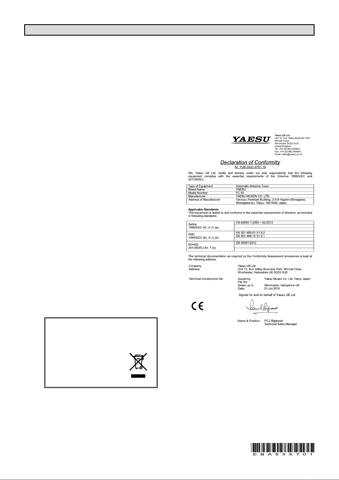
Disposal of your Electronic and
Electric Equipment
Products with the symbol (crossed-out wheeled bin) can-
not be disposed as household waste.
Electronic and Electric Equipment should be recycled
at a facility capable of handling these items
and their waste byproducts.
In EU countries, please contact your local
equipment supplier representative or service
center for information about the waste col-
lection system in your country.
Specications
Frequency Range : 1.8 MHz ~ 29.7 MHz , 50 MHz ~ 54 MHz
Input Impedance : 50 Ω
Maximum Power : 100 Watts
Tune-up Power : 4 W ~ 60 W
Tune-up Time : 5 seconds or less
Impedance Matching Range : 1.8 ~ 29.7 MHz = 16 Ω ~ 150 Ω
50 ~ 54 MHz = 25 Ω ~ 100 Ω
Impedance Matching Memories : 100 channels
Input Voltage Requirement :13.8 V ±15 % (supplied from transceiver)
Operating Temperature Range : 14° F ~ 122° F (−10 °C ~ +50 °C)
Case Size (WHD) : 6.1” x 1.8” x 8.3” (155 x 45 x 210.5 mm)
Weight : 1.35 kg (3 lb.)
Specications subject to change without notice or obligation.
YAESU MUSEN CO., LTD.
Tennozu Parkside Building
2-5-8 Higashi-Shinagawa, Shinagawa-ku, Tokyo 140-0002 Japan
YAESU USA
6125 Phyllis Drive, Cypress, CA 90630, U.S.A.
YAESU UK
Unit 12, Sun Valley Business Park, Winnall Close
Winchester, Hampshire, SO23 0LB, U.K.
1608O-AO
YETA00412
Other manuals for FC-50
1