TABLE OF CONTENTS
SRM-2620ES, SRM-2620TES
T262XS, C262S
T262TXS, C262TS 1
Page Page
1 SERVICE INFORMATION.....................................2
1-1 Specifications...................................................2
1-2 Technical data ..................................................3
1-3 Torque limits.....................................................5
1-4 Special repairing materials...............................5
1-5 Service limits....................................................6
1-6 Special tools.....................................................7
2 STARTER SYSTEM..............................................8
2-1 Disassembling starter assembly.......................9
2-2 Replacing starter rope....................................10
2-3 Replacing rope guide .....................................12
2-4 Installing rewind spring...................................12
2-5 Assembling starter..........................................13
2-6 Replacing starter pawl....................................15
3 IGNITION SYSTEM.............................................17
3-1 Troubleshooting guide....................................17
3-2 Testing spark..................................................18
3-3 Inspecting spark plug .....................................18
3-4 Inspecting ignition switch................................19
3-5 Replacing ignition switch................................20
3-6 Inspecting ignition coil resistance...................23
3-7 Replacing spark plug cap and coil..................24
3-8 Replacing ignition coil.....................................24
3-9 Setting pole shoe air gaps..............................25
3-10 Inspecting flywheel and key ...........................25
4 FUEL SYSTEM ...................................................27
4-1 Cleaning air filter ............................................28
4-2 Checking fuel cap and fuel strainer................28
4-3 Inspecting fuel tank and tank vent..................29
4-4 Replacing fuel line, fuel return line, tank vent
line and grommet............................................30
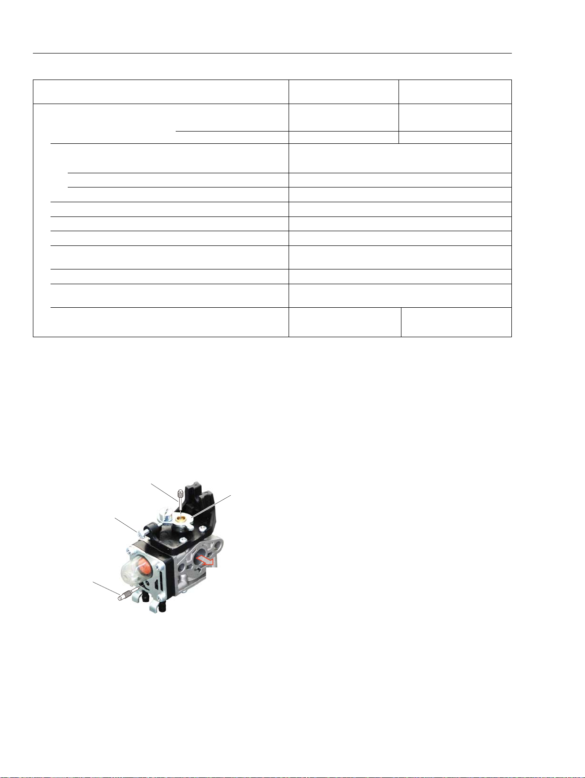
4-5 Adjusting carburetor.......................................32
4-5-1 General adjusting rules ..................................32
4-5-2 Initial setting Throttle adjust screw, L mixture
needle and H mixture needle ........................32
4-5-3 Adjusting carburetor.......................................33
4-6 Testing carburetor...........................................34
4-7 Inspecting crankcase pulse passage .............35
4-8 Inspecting metering lever height ....................35
4-9 Inspecting inlet needle valve..........................36
4-10 Inspecting diaphragm and others...................36
4-11 Replacing throttle cable and control parts......37
4-12 Checking and adjusting throttle cable ............37
5 CLUTCH SYSTEM..............................................38
5-1 Removing clutch shoes and springs...............39
5-2 Installing clutch shoes....................................39
5-3 Removing clutch drum....................................40
5-4 Removing clutch drum bearings.....................41
5-5 Installing bearings and clutch drum................41
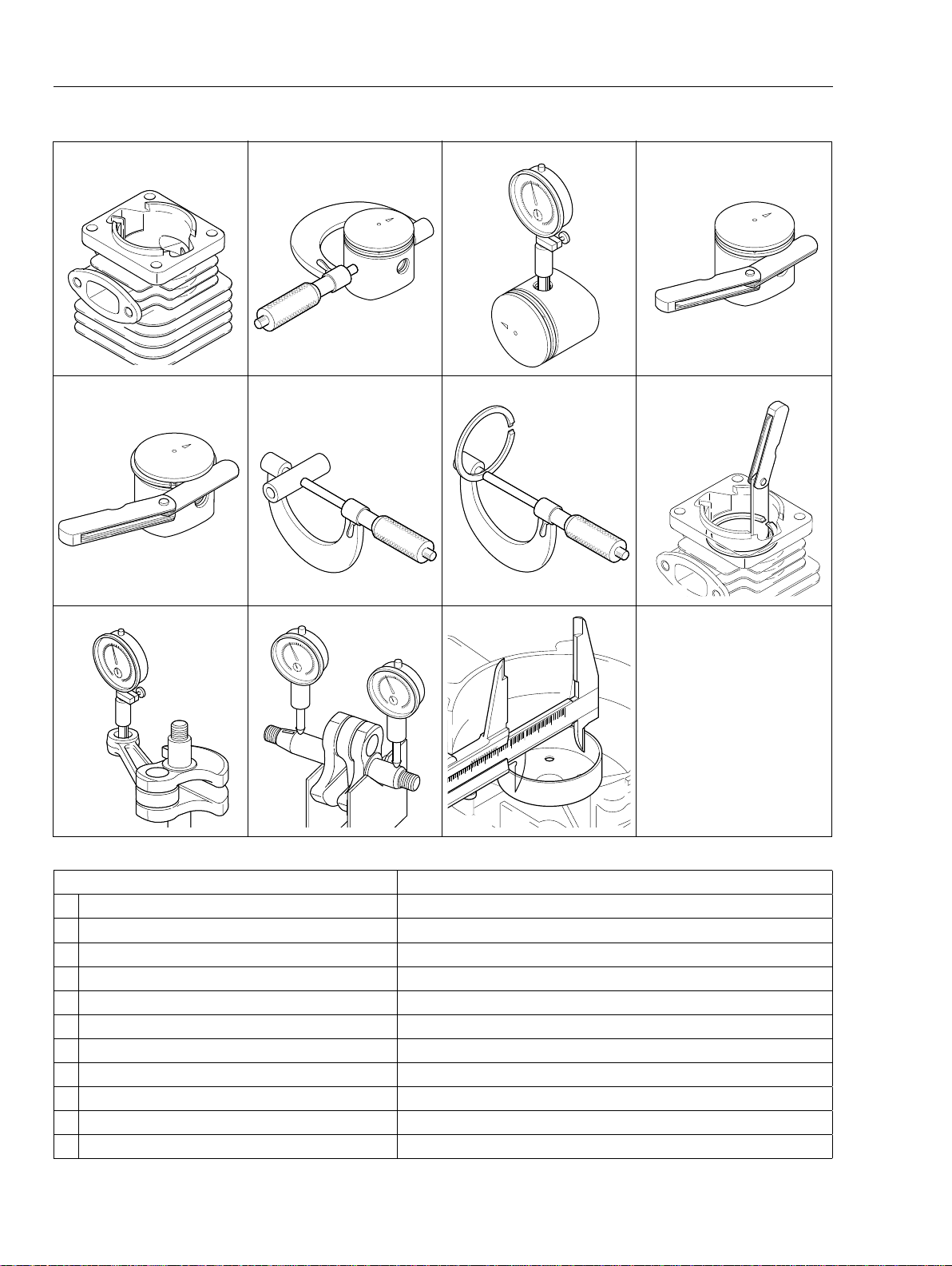
6 ENGINE...............................................................42
6-1 Testing cylinder compression.........................43
6-2 Cleaning cooling air passages .......................43
6-3 Inspecting muffler and exhaust port...............44
6-4 Testing crankcase and cylinder sealing..........45
6-5 Removing and inspecting cylinder..................45
6-6 Inspecting piston and piston ring....................46
6-7 Replacing needle bearing...............................46
6-8 Inspecting crankcase and crankshaft.............47
6-9 Replacing oil seal...........................................47
6-10 Replacing ball bearing....................................48
6-11 Assembling crankshaft and crankcase...........48
6-12 Installing piston...............................................49
6-13 Installing piston ring and cylinder...................49
7 CUTTER DRIVE SYSTEM..................................50
7-1 Disassembling gear case...............................52
7-2 Replacing gears and PTO shaft.....................53
7-3 Assembling gear case....................................55
8 MAINTENANCE GUIDE......................................56
8-1 Service Intervals.............................................56
8-2 Disassembly Chart.........................................57
8-3 Troubleshooting guide....................................58