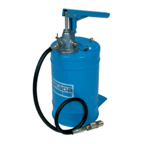
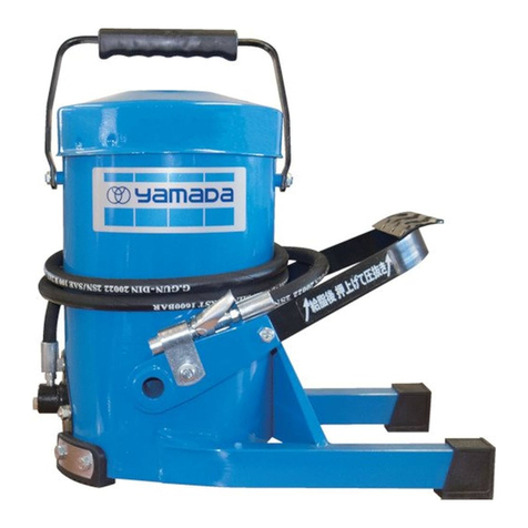
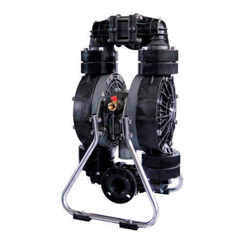
YAMADA VO-50 User manual

Doc. No. OSA 042U-03
VOLUME BUCKET PUMP
VO-50 MODEL No.880133
WARNING
Prior to operating this pump, be sure to read this operation manual for safety. After reading the manual, please
keep it at hand any time for your quick reference.
INSTRUCTION

1
Preface
This instruction manual describes how to use this product properly and what care should be
taken, intended that it will serve you well without fault.
Before reading the manual, never operate the product.
Read precautions carefully. Keep this manual handy.
If you find any questions, doubts, or problems in our products, contact our distributors from which
you made a purchase or our sales offices described on the back of this manual.
If this instruction manual or caution labels are damaged or lost, buy other ones from which you
made a purchase. Save this manual and affix the labels properly.
Contents
1. Purpose of use ········································································ 2
2. Warning / Caution ···································································· 2
2-1.Definition of warning and caution ············································ 2
3. Precautions ············································································ 2
4. Name of each section ······························································· 3
4-1.Packing············································································· 3
5. Preparation before use······························································ 4
6. How to use ·········································································· 5
7. Maintenance and Inspection ···················································· 6
7-1. Inspection of malfunctions and troubleshooting ························· 6
7-2. Maintenance and Inspection·················································· 6
7-3. Disassembly and Assembly ················································· 6
7-4.Exploded parts view / Parts list ··············································· 8
8. Specifications ········································································ 9
8-1. Specifications ···································································· 9
8-2. Accessories······································································· 9
9. Limited Warranty······································································ 10

2
1. Purpose of use
This machine is a pump to supply oil, in particular, high-viscosity oil to construction machines by
using a lever type manual pump. It cannot be used for grease. The machine can keep a large
quantity of oil in its cabinet and is most suitable for lubrication work in an outdoor place where no
compressor is available. The oil supply port base is a button head type that permits quick and
sure lubrication.
2. Warning / Caution
2-1.Definition of warning and caution
WARNING
The following definitions and warning indications are given to specify "warning" and "caution" in
this instruction manual.
A warning indication is indispensable to your safe work.
Be sure you understand these indications well before use since the important items to prevent
personal injury and physical damage are described on it.
Warning: Given when it is assumed that mishandling may cause death or serious injury.
Caution: Given when it is assumed that mishandling may cause injury and physical
damage.
*NOTE:The above labels are intended to improve efficient operation and perform device
maintenance.
3.Precautions
WARNING
-Some types of oil to be used may contain carcinogens. Read the precautions provided by oil
manufacturer thoroughly and handle the oil with care.
- Gasoline is a high-volatility fuel. Do not use it to clean the pump in any case. Otherwise,
ignition or explosion may be caused.
CAUTION
- This machine is a pump for high-viscosity oil. The machine cannot be used for gasoline, light
oil, kerosene, and other solvents.
For your safe use
A warning label is affixed on this product and with which precautions are described to call
attention to your safe use.
Never fail to observe precautions to prevent any personal injury, physical damage, and accidents
Be sure to observe warning and caution described below since they are very important.
CAUTION
WARNING

3
4.Name of each section
4-1 Packing
The main devices and accessories of this machine are packaged in respective corrugated
fiberboard cases. Open the upper part of each corrugated fiberboard case and check the pump
assembly and oil tank for damage, and also check whether the package includes all the
accessories.
Pump Assy
Nipple
Cove
r
Wing Bolt
Check Valve
Delivery Hose
Coupler

4
5. Preparation before use
1) Install the attached oil resisting hose at the oil
discharge port of the pump assembly. Screw the
hose completely by hand and tighten it with a
spanner so that it may not loosen. (Fig. 1)
2) Raise the pump handle and loose the 2 left and
right thumbscrews that fix the top-surface cover of
the oil tank. Then, shift the cover toward the right.
(Fig. 2)
3) Lower the handle and push it toward the right with
force to shift the handle position about 45ºC.
(Fig. 3)
When shifting the handle toward the right, step on
the footboard so as not to move the oil tank and
shift the handle by pushing the upper part of the oil
tank with a single hand.
4) Wipe the inside of the oil tank with a clean waste
cloth and change the applied oil. Take care not to
mix sand or dust in the oil.
5) Return the handle and the cover to their initial
positions and tighten the thumbscrews of the cover.
(Fig. 4)
6) Tighten the check valve provided on the right side
of the pump and operate the handle up/down to
bleed air in the pump and hose.
Continue this operation until oil is discharged from
the base.
Fig.1
Fig.2
Fig.3
Fig.4

5
6. How to use
1) Wipe the base and the opposite oil supply port base
with a clean waste cloth.
2) Adjust the base groove to the oil supply port base and
set it securely by sliding.
Note that oil leakage may occur if this set status is
incomplete.
3) Tighten the check valve. If the check valve is loose,
the pressure cannot be increased. (Fig. 5)
4) Step on the footboard so as not to move the oil tank
and operate the handle up/down slowly to supply oil.
(Fig. 6)
5) After completion of the oil supply, loosen the check
valve to bleed the internal pressure of the pump and
hose. Then, remove the base from the oil supply port
base.
CAUTION
If the base is removed from the oil supply port base
before the check valve is loosened, oil will be
discharged from the pump and hose, thereby
contaminating the surroundings.
6) After completion of lubrication for all positions,
loosen the check valve to bleed the internal
pressure of the pump and hose, and hang the base
on the base hanger without being contaminated.
(Fig. 7)
CAUTION
- When operating the handle, do not insert the hand into a clearance between the handle
and the handle stopper. An unexpected injury may be caused by nipping.
Fig.7
Fig.6
Fig.5

6
7. Maintenance and Inspection
7-1. Inspection of malfunctions and troubleshooting
Symptom Cause
Contents of inspection and
corrective measure
Oil does not come out by
operating the handle.
Check whether the check valve is
closed.
- Check whether oil is used up.
Check the check valve.
Check and replenish.
Oil comes out but the pressure
or flow rate is insufficient.
- The valve is clogged with dust.
-The plunger packing is
worn away.
Check and clean the valve.
Check and replace.
Oil comes out from the top of
the gland.
- The gland packing is
worn away.
Tighten and replace with a
new one.
7-2. Maintenance and Inspection
* The hose is a consumable part. Check it periodically. If any flaw or leak is found, replace it a
little early.
7-3. Disassembly and Assembly
[Disassembling and inspecting the suction section]
1) Unscrew the oil resisting hose to remove it.
2) Loosen the pan-head screws that fix the pump unit on the oil tank and take out the pump
assembly from the oil tank. At this time, the ball spring provided between the pump unit and
hose hanger will jump out. Take care not to lose it.
3) Fix the main unit on the vice.
4) Loosen the 2 bolts/nuts of the tube adapter that fix the flange.
5) When the suction tube is loosened with a pipe wrench set on this tube, it can be separated
from the main unit.
6) Fix the suction tube on the vice and unscrew it with the pipe wrench set on the valve adapter.
Then, the valve can be taken out.
WARNING
Gasoline is a high-volatility fuel. Do not use it to clean the pump in any case. Otherwise,
ignition or explosion may be caused.

7
7) Next, fix the lot on the vice and unscrew it with a spanner set on the ball sheet. Then, the
arm-shaped packing, ball, and spring can be taken out. Clean and check each part. If any
flaw or abrasion is found, replace it with a new one. In particular, check the sheet surfaces of
the valve and ball carefully.
8) After checking and replacement, assembly parts as they were taking care about the direction
of each part. For assembly, reverse the disassembly procedure.

8
No. Parts No. Descriptions Q’ty
1 703972 Handle 1
2 830410 Lever Support Assy 1
3 703575 Pin 1
4 703576 Pin 1
5 703577 Pin 1
6 631013 Washer 3
7 632039 Cotter pin 3
8 703161 Cap 1
9 703162 Packing Gland 1
10 770328 Packing 1
11 830267 Check Valve 1
12 640005 O-Ring 1
13 703164 Body 1
14 701923 Union 1
15 770329 Ring Packing 1
16 703116 Flange 1
17 703169 Tube Adapter 1
18 627010 Nut 2
19 611099 Bolt 2
20 703167 Suction Tube 1
21 703168 Rod 1
22 703153 Plunger 1
23 770326 L-Packing 1
24 703154 Washer 1
25 703152 Spring 1
26 630321 Ball 1
27 703155 Ball Seat 1
28 703170 Washer 1
29 703171 Valve 1
30 703172 Valve Adapter 1
No. Parts No. Descriptions Q’ty
1 703146 Knob 1
2 610619 Wing Bolt 2
3 703974 Cover 1
4 770361 Packing 1
5 830265 Oil Tank Assy 1
6 602299 Screw 3
7 631418 Sprig Washer 3
8 770327 Packing 1
9 602760 Screw 2
10 630321 Ball 1
11 702614 Spring 1
12 702613 Nipple Holder 1
13 703148 Nipple Holder 1
14 850350 Pump Assy 1
15 695055 Delivery Hose 1
16 800894 Coupler 1
17 682636 Tapping Screw 1
7-4. Exploded parts view / Parts list
880133 VO-50
850350 Pump Assy

9
No. Parts No. Descriptions Q’ty
1 704466 Cap 1
2 703000 Washer 1
3 770311 Packing 1
4 703001 Washer 1
5 703002 Spring 1
6 772676 Packing 1
7 703003 Union 1
8 703004 Spring 1
9 630316 Ball 1
10 702589 Washer 1
11 703005 Union 1
12 703006 Spring 1
13 703007 Washer 1
14 770312 L-Packing 1
15 703009 Uion 1
16 703008 Cap Nut 1
800894 Coupler
8.Specifications
8-1. Specifications
The mark * denotes a reference value when machine oil #160, accessory hose, and accessory
base are used.
8-2.Accessories
* When the standard hose is not enough in length or it is used for a large button head nipple, use the
special hose and base that are available as options.
695107 Delivery Hose (length 3m)
800628 Coupler (for big button head nipple)
Product
number Model Capacity Height Weight Accessory
880133 VO-50 15L 530mm 9.6kg
695055 Delivery Hose 1
800894Coupler 1
Pump
number Discharge volume Exhalation pressure*
850350 24CC / 1 stork 5MPa
800628 Coupler
Size (big button head nipple)

10
9. Limited Warranty
If an abnormality occurs during normal operation in accordance with the operating instructions and
other operating cautions within the warranty period (12 months after date of purchase) that can be
attributed to a manufacturing defect, the defective parts of this product will be serviced or the product
will be replaced free of charge. However, this warranty will not cover compensation for incidental
damage or any malfunction listed below.
1. Warranty period
This warranty will be valid for a period of 12 months after the date of purchase.
2. Warranty
If, during the warranty period, any of the material of the genuine parts of this product or the
workmanship of this product is found defective, and is so verified by our company, the servicing cost
will be fully born by our company.
3. Exclusion
Even during the warranty period, this warranty does not cover the following.
1) Malfunction arising from use of parts other than manufacturer-specified genuine parts
2) Malfunction arising from misuse or operating errors, or lack of storage or maintenance care
3) Malfunction arising from use with a fluid that may cause corrosion, inflation or dissolution of the
component parts of the product
4) Irregularity arising from repair made by other than by our firm, our regional office, dealer or
authorized service personnel
5) Malfunction arising from modification of the product by other than authorized service personnel
6) Wear and tear of parts that must be regularly replaced in the course of normal operation, such
as packings, O-rings and hose.
7) Malfunction and/or damage due to use with incorrect voltage.
8) Malfunction and/or damage due to transportation, moving or drop page of the product after
purchase
9) Malfunction and/or damage due to fire, earthquake, flood or other force majeure
10) Malfunction arising from use of compressed air that contains impurities or excessive moisture,
or use of gases or fluids other than the specified compressed air
11) Malfunction arising from use of excessively abrasive material or of inadequate grease.
Furthermore, this warranty does not cover the rubber parts, or other parts used in this product and its
accessories, which are subject to wear in normal operation.
・hoses ・packings ・cords
4. Parts
Parts for this product will be kept available for 5 years after discontinuation of production. Once 5
years have elapsed after close of production, availability of parts for this product cannot be
guaranteed.

201805 OSA042U
Manufactured by
YAMADA
CORPORATION
INTERNATIONAL DEPARTMENT
1-1-3 Minami Magome, Ohta-ku, Tokyo 143-8504, Japan
PHONE : +81-(0)3-3777-0241
FAX : +81-(0)3-3777-0584
Table of contents
Other YAMADA Water Pump manuals

YAMADA
YAMADA 40 Series User manual

YAMADA
YAMADA DP-20F/P User manual

YAMADA
YAMADA DP Series User manual

YAMADA
YAMADA 140 Series User manual

YAMADA
YAMADA DP-10F User manual

YAMADA
YAMADA NDP-P50 User manual

YAMADA
YAMADA NDP-25 series User manual

YAMADA
YAMADA SH-160A10 User manual

YAMADA
YAMADA FB-8 User manual

YAMADA
YAMADA NDP-H50 User manual

YAMADA
YAMADA SK-55 User manual

YAMADA
YAMADA VO-8 User manual

YAMADA
YAMADA NDP-40 series User manual
YAMADA
YAMADA DP-Fs Series User manual

YAMADA
YAMADA Global Series User manual
YAMADA
YAMADA Global Series User manual

YAMADA
YAMADA DR-50B1SUS User manual

YAMADA
YAMADA SH-125B Series User manual
YAMADA
YAMADA 110 Series User manual
YAMADA
YAMADA NDP-P20 Series User manual