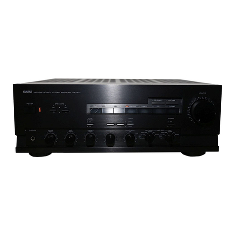
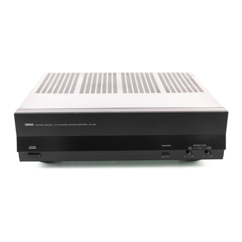
Yamaha P2075 User manual

YAMAHA
Power
Amplifier
P2075
Operating
Manual
CHANNEL
A
CHANNEL
В
PROTECTION
SIGNAL
CLIP
Bru
СЫР
о
o
18 16
14
12
ag
16,14
yo
20,

HOW
TO
USE
THIS
MANUAL
If
you
are
an
engineer
or
technician
who
is
familiar
with
sound
system
design,
much
of
this
manual
will
serve
as
a
review
for
you.
The
basic
features
are
|
presented
in
the
"BRIEF
OPERATING
INSTRUCTIONS”
section.
Check
this
and
the
“SPECIFICATIONS”
section,
and
you
will
see
most
of
what
you
need
fo
know.
If
you
would
like
to
know
more
about
AC
power
distribution
and
safety,
grounding,
speaker
systems,
crossovers,
and
so
forth,
this
information
is
also
presented.
Check
the
Table
of
Contents.
Due
to
common
usage
and
for
convenience,
we
will
sometimes
refer
to
dual-
channel
amplifiers
ағ
"stereo"
models
....
especially
because
they
have
a
rear-
panel
MONO/STEREO
switch.
Bear
in
mind,
however,
that
the
two
channels
may
be
used
for
dual
monaural
programs,
for
two
sections
of
a
bi-amplified
speaker
system,
or
for
bridged
monaural
operation
—
so
"stereo"
is
not
neces-
sarily
an
accurate
description
of
the
amplifier
in
every
application.
TABLE
OF
CONTENTS
ІМТНОПОСТІОМ...........................
2
How
crossover
networks
operate
and
what
they
do
..
25
BRIEF
OPERATING
INSTRUCTIONS
............
3
The
difference
between
low
and
high
level
Front
Рапе!.............................
3
CYOSSOVEIS
.............................
26
Rear
Рапе!..............................
4
The
pros
and
cons
of
low
level
and
high
level
Amplifier
Operation
.......................
5
СГОЗЗОМе!
.............................
26
Precautions
regarding
AC
power
source
for
amplifiers
.
5
The
meaning
of
various
amplifier
power
rating
INSTALLATION
...........................
6
methods
..............................
28
Input
Connections...
6
PROTECTION
FOR
SPEAKERS.
...............
29
Output
Connections
.......................
7
Output
relay
...........................
29
MORE
INFORMATION
ON
SOUND
SYSTEM
WIRING
.
9
Current
limiting
........................
-,
29
Balanced
and
unbalanced
wiring
.............-
9
Speaker
Ғи5ес...........................
29
Why
input
transformers
sometimes
are
used.
......
10
Compressor/limiters
..............
ИО
30
Noise
and
losses
іп
low
impedance
and
high
Equalizers
and
filters
................
0000
ee
30
impedance
Нпез...............
ежа
‚
91
High
frequency
driver
protection
networks
Signal
levels,
dynamic
range
and
headroom
......,
11
(Якев)...............................
30
Сғоипдіпа.............................
14
SPECIFICATIONS
.........................
32
|
AC
outlet
wiring
affects
grounding
and
safety
.....
17
DIMENSIONS
............................
32
|
Speaker
Мігіпе..........................
:19
.
BLOCK
DIAGRAM
........................
33
|
.
Distributed
speaker
systems
and
constant
voltage
lines
22
PERFORMANCE
GRAPHS
...................
24
|
How
to
calculate
amplifier
power
output
in
bridged
|
|
MONO
тоде......:....................
23
MULTI-AMPLIFIED
SPEAKER
SYSTEMS
(Biamping,
triamping
and
so
forth)
...................
...
24
INTRODUCTION
-
This
manual
describes
the
P2075
power
amplifier.
The
P2075
is
dual-channel
amplifier
rated
at
50
watts
into
8
ohms
or
75
watts
into
4
ohms.
This
amplifier
is
equipped
with
features
that
make
it
well
suited
to
a
variety
of
sound
reinforcement,
recording
and
musical
instrument
applications.
Electronically
balanced,
differential
input
circuits
allow
the
use
of
long,
shielded
3-wire
input
cables
to
reduce
susceptibility
to
hum.
Each
input
appears
at
an
XLR
connector
and
a
pair
of
phone
jacks.
The
XLR
inputs
combine
the
advantages
of
electrostatic
and
electromagnetic
noise
rejection,
with
locking
terminals
that
won't
pull
out
accidentally
should
the
cable
be
tugged.
The
phone
jacks
provide
for
fast,
compatible
connection
to
equip-
ment
that
utilizes
phone
jack
outputs.
The
output
circuitry
is
fully
protected
from
overloads
and
short
circuits,
and
the
speaker
outputs
are
relay-protected
against
turn-on
transients
and
DC
offset.
Protec-
tion
circuitry
is
activated
and
the
PROTECTION
LED
blinks
when
the
heat
sink
temperature
exceeds
60°С.
For
General
model,
when
the
heat
sink
temperature
exceeds
85^C,
the
relay
is
turned
off
and
output
is
cut.
Output
connections
are
made
via
either
phone
jacks
or
5-way
binding
posts.
The
binding
posts
provide
more
secure
wiring,
better
current-handling
capability,
and
less
tendency
to
build
up
contact
resistance
than
typical
phone
jack
outputs.
Phone
jack
.
outputs
are
provided
for
convenience
in
fast
setup
situations.
The
amplifiers
are
rated
for
4-ohm
or
higher
impedance
loads.
When
mounting
the
P2075
in
any
standard
19”
electronic
equipment
rack,
cooling
fans
maybe
required
when
it
must
produce
extremely
high
average
power
output.
This
amplifier
is
professional
in
every
detail,
right
down
to
the
input
attenuators
—
recessed
controls
with
31
calibrated
positions
and
rubber
security
caps.
Rather
than
experiment
with
exotic
designs,
Yamaha
has
applied
field-proven
principles
to
design
amplifiers
which
are
highly
stable
and
which
should
deliver
the
kind
of
reliability
for
which
Yamaha
has
earned
a
solid
reputation.
As
with
any
product,
however,
proper
installation
and
use
is
essential
to
success.
This
manual
has
been
prepared
to
assist
you
in
getting
the
most
out
of
your
new
Yamaha
power
amplifier.
We
encourage
you
to
read
it
thoroughly.

BRIEF
OPERATING
INSTRUCTIONS
Front
Panel
PROTECTION
|
POWER
AMPLIFIER
P2075
©
INPUT
ATTENUATOR(S)
The
P2075
has
two
log-linear
input
attenuators.
Each
control
is
marked
in
31
dB-calibrated
steps,
and
detented
for
extra
accuracy.
The
attenuators
provide
a
smooth,
noise-free
transition
from
maximum
level
(zero
attenuation)
to
silence
(“infinite”
attenuation).
The
attenuators
are
recessed
(flush
with
the
front
panel)
to
avoid
damage
or
accidental
setting
changes.
Calibrated
input
attenuators
offer
numerous
advantages.
They
allow
predictable
and
repeatable
setups
in
portable
sound
systems,
as
well
as
in
permanently
installed
systems
which
are
pre-checked
in
the
shop
and
later
installed
at
another
location.
Whether
the
amplifiers
are
used
on
stage
in
portable
sound
systems
or
installed
in
studios,
factories,
meeting
rooms,
theatres,
arenas
or
elsewhere,
their
calibrated
attenuators
allow
easy,
accurate
input
sensitivity
adjustments.
The
calibrated
attenuators
permit
operators
to
adjust
the
level
of
two
channels
with
precise
tracking.
@
INPUT
LEVEL
INDICATORS
(SIGNAL,
CLIP)
A
pair
of
LEDs
above
the
input
attenuator
monitor
the
signal
level.
The
green
"SIGNAL"
LED
turns
on
whenever
the
signal
present
at
the
amplifier
output
is
2
volts
RMS
or
higher.
Since
this
is
equivalent
to
1
watt
into
a
4-ohm
load,
or
1/2
watt
into
an
8-ohm
load,
the
SIGNAL
LED
basically
indicates
that
some
program
material
is
present.
The
red
“CLIP”
LED
turns
on
when
the
output
stage
is
about
to
clip,
either
from
an
overdriven
input
or an
overloaded
output.
This
"flags"
the
operator,
suggesting
the
attenuator
be
turned
down
or
the
speaker
load
corrected
to
avoid
distor-
tion.
Fig.
1
POWER
SWITCH,
POWER
&
PROTECTION
INDI-
CATORS
An
alternate-action
switch
turns
the
AC
power
on
and
off.
When
the
power
is
ON,
a
red
LED
immediately
above
the
switch
is
illuminated.
Immediately
after
turning.
power
оп,
a
second
red
LED
above
the
PROTECTION
label
will
also
be
on,
indicating
the
speaker
output
is
disconnected
from
the
load
by
a
protection
relay.
After
a
few
seconds,
the
PRO-
TECTION
LED
should
turn
off,
indicating
that
the
outputs
is
activated
(the
slight
delay
allows
time
for
the
internal
amplifier
circuits
to
stabilize
and
thus
avoid
turn-on
thump).
The
PROTECTION
LED
blinks
when
the
heat
sink
tempera-
ture
exceeds
60°C.
For
General
model,
at
a
heat
sink
tem-
perature
of
85°
С
the
relay
is
turned
off
and
output
is
cut.
HINT
REGARDING
TURN-ON
OF
THE
POWER
AMPLIFIER
Unless
you
are
turning
on
all
the
equipment
in
the
sound
system
simultaneously
with
a
switched
strip
of
power
outlets,
be
sure
to
turn
on
everything
else
before
you
turn
on
the
amplifier(s).
By
turning
on
the
power
amplifier
last,
you
can
prevent
turn-on
“thumps”
generated
by
the
console,
graphic
EQ,
electronic
cross-
over,
or
other
accessory
signal
processors
from
possibly
damaging
speakers.
The
opposite
procedure
should
be
used
to
shut
off
the
system:
first
turn
off
the
ampli-
fiers,
then
the
rest
of
the
equipment.
This
power
amplifier
has
a
relay
which
is
timed
to
turn
on
the
speaker
outputs
after
the
amplifier’s
power
supply
is
fully
charged
up,
thus
preventing
any
turn-on
noise.
Timing
of
the
amplifier’s
turn-on
circuit
is
usually
sufficient
to
accommodate
all
the
turn-on
anomalies
from
other
pieces
of
gear
in
a
system,
making
it
accept-
able
to
use
a
single
switched
power
strip
in
a
perma-
nently
installed
or
“packaged”
portable
sound
system.

Rear
Panel
CAUTION
то
REDUCE
THE
RISK
OF
ELECTRIC
SHOCK,
DO
NOT
REMOVE
COVER.
NO
USER
SERVICEABLE
PARTS
INSIDE
REFER
SERVICING
TO
QUALIFIED
SERVICE
PERSONNEL
ATTENTION
arin
OE
REDUIRE
LE
RISQUE
DE
CHOC
ELECTRIQUE.
NE
PAS
ENLEVER
LE
COUVERCLE.
IL
NE
SE
TROUVE
A
L'INTERIEUR
AUCUNE
PIECE
POUVANT
ETRE
REPAREE
PAR
L'USAGER
SADRESSER
A
UN
REPARATEUR
COMPETENT.
MONO
MODE
OPERATION-SEE
INSTRUCTION
MANUAL
FOR
CORRECT
SPEAKER
IMPEDANCE
POUR
LE
МООЕ
MONAURALCONSULTEZ
LE
MANUAL
O'OPERATION
POUR
VOUS
ASSURER.
DE
10
IMPEDANCE
ADEQUATE
DES
HAUT-PARLEURS,
MODE
CHANNEL
Bn
INPUT
à
©
INPUT
CONNECTIONS
Input
connectors
for
each
channel
include
one
female
XLR
connector
(electronically
balanced)
plus
1/4-inch
Tip/Ring/
Sleeve
phone
jack
(for
balanced
or
unbalanced
lines).
Pin
2
of
the
XLR
is
wired
as
the
“hot”
lead
satisfying
DIN/JIS
and
IEEE
standards.
This
corresponds
to
the
tip
of
the
T/R/S
phone
jacks.
Unbalanced
T/S
phone
plugs
may
be
used,
as
well
as
balanced
T/R/S
plugs.
©
MODE
SWITCH
(MONO/STEREO)
This
two-position
switch
selects
the
operating
mode
of
the
STEREO
or
MONO:
STEREO
mode
selects
independent
operation
of
each
amplifier
channel.
Facing
the
rear
panel,
the
right-hand
pair
of
(*)
and
(—)
terminals
carry
signal
for
the
Channel
A
speaker
load,
and
the
left
pair
of
(+)
and
(—)
terminals
to
the
Channel
B
load.
:
МОМО
mode
rewires
the
two
channels
for
bridged
mono
operation.
Only
the
Channel
A
input
attenuator
and
input
connectors
are
operative.
Connect
the
speaker
load
to
the
two
red
(+)
terminals
for
Channels
А
and
B;
the
Channel
А
(+)
terminal
has
the
same
polarity
as
pin
2
of
the
XLR
or
the
(*)
input
terminal.
Do
not
allow
either
of
the
speaker
wires
to
contact
any
other
wire,
chassis,
rack
or
connector.
Q
SPEAKER(S)
OUTPUT
CONNECTIONS
Each
channel's
output
is
brought
to
three
connection
points
(all
wired
in
parallel):
a
pair
of
5-way
binding
posts
and
two
1/4-іпсһ
Tip/Sleeve
phone
jacks.
The
red
(+)
and
black
(—)
terminals
of
the
5-way
binding
posts
are
the
preferred
connections
for
normal
operation.
However,
many
speaker
systems
are
equipped
with
phone
jack
inputs,
and
the
amplifier's
phone
jack
outputs
provide
a
convenient
means
to
connect
to
such
speakers
with
standard
phone-to-phone
unshielded
cables.
While
all
three
output
connections
may
be
used
simul-
taneously,
make
sure
the
combined
load
is
no
less
than
4
ohms.
See
the
"Speaker
Wiring"
subsection
of
the
MORE
INFORMATION
ON
SOUND
SYSTEM
WIRING"
section.
TO
RAIN
OR
MOISTURE
МАХ.
RMS
OUTPUT
75W/4Q
+173,
SP
WIRING.CLASS
2
WIRING
MAY
BE
USEO.
STEREO.
MADE
IN
JAPAN
MAX.RMS
OUTPUT
М/С
(34
6V)
АИ
төледік.
|І
CHANNEL
=—=
A
(MONO!
CHANNEL
B
WARNING
то
REDUCE
THE
RISK
OF
FIRE
OR
ELECTRIC
SHOCK
,
DO
NOT
EXPOSE
THIS
PRODUCT
(ЮҮАМАНА
РОМЕН,
кенімен
PRIMARY
"A
FUSE
120V
250W
ЗООМА
БОН;
~
БА
125У
SPEAKERS:
1and2-8-160.
SPEAKER
1012
4-160
/
SPEAKER.
2
FIRE
REPLACE
ONLY
WiTH
SAME
TYPE
FUSE.
ATTENTION
AFIN
DE
REDUIRE
LE
RISQUE
DE
FEU.
REMPLACER
UNIQUEMENT
PAR
UN
FUSIBLE
DE
MEME
TYPE.
U.S.
&
Canadian
models
Fig.
2
CAUTION
NEVER
USE
COIL
CORDS
FOR
SPEAKER
HOOKUP.
Coiled,
and
even
many
non-coiled,
guitar-type
cords
usually
have
higher
internal
resistance
than
the
speakers
themselves.
High
resistance
is
due
to
the
thin
wires
used
to
keep
the
cords
flexible
(guitar
cords
are
not
intended
to
carry
a
lot
of
power,
so
they
don't
need
thick
wires).
Such
cords
prevent
most
of
the
power
from
reaching
the
speakers,
and
instead
heat
up.
In
high
power
operation,
a
guitar-type
cord
can
melt
and
cause
a
fire
hazard.
Use
heavy
gauge
speaker
cords
with
phone
plugs
if
you
must
use
phone
plug
connections
at
all;
shielded
cable
is
not
necessary
or
desirable
for
speaker
connections.
©
FUSE
Given
reasonable
ambient
temperatures,
and
free
air
circula-
tion
for
the
amplifier's
cooling
system,
the
output
transistors
and
heat
sinks
should
be
able
to
handle
maximum
power
output
indefinitely,
but
in
the
event
of
a
power
supply
problem,
or
should
there
be
a
problem
with
the
power
mains
themselves,
some
form
of
protection
is
required.
This
fuse
can
be
of
some
value
in
protecting
the
power
supply
against
power-line
surges
and
long-term
overloads
at
the
outputs.
The
amplifier
is
designed
to
avoid
unwanted
shutoff
during
a
live
performance,
but
it's
better
to
blow
a
fuse
and
replace
it
than
to
loose
the
amp
altogether.
NOTE:
A
thermal
breaker
is
included
within
the
amp,
and
reaches
85°С
for
General
model
and
for
all
models,
a
protec-
tion
LED
will
begin
to
blink
when
the
heat
sink
temperature
exceed
60°C,
If
there
is
no
output,
and
the
fuse
is
not
blown,
the
problem
may
be
overheating;
wait
for
the
unit
to
cool,
and
it
should
come
back
on
line.
|
WARNING
ONLY
USE
FUSES
OF
THE
SAME
RATING
AND
TYPE
AS
THE
ORIGINAL
FUSE
SPECIFIED
FOR
THE
POWER
AMPLIFIER.
This
information
is
prínted
on
the
amplifier
rear
panel,
and
is
repeated
here
for
convenience:
U.S.
&
Canadian
тодйе15...............
5A
125V
General
model
....................
2.5A
250V

Amplifier
Operation
This
procedure
applies
to
mono
systems
(stereo
amp
in
bridged
mode),
as
well
as
to
stereo
sound
systems.
It
applies
to
full-range
speaker
systems
which
have
a
passive
high-level
crossover
(or
none
at
all).
If
you
are
using
the
amplifiers
іп
a
multi-amplified
system
with
an
electronic
or
low-level
passive
crossover,
the
Input
Attenuators
on
the
amplifier
are
generally
set
to
maximum
(zero
loss),
and
all
level
con-
trolling
is
done
at
the
crossover
(skip
step
10).
-—
.
Make
certain
all
equipment
is
OFF.
2.
Plug
the
amplifiers
into
a
grounded
120
Volt,
50—60
Hz
AC
power
outlet.
3.
Connect
the
wiring
from
the
signa!
sources
to
the
ampli-
fier's
input
(XLR
or
phone
jack).
4.
Select
the
appropriate
.setting
for
the
MODE
switch
(MONO
or
STEREO).
5.
Connect
the
speakers
to
the
output
terminals
or
phone
jacks.
If
used
in
the
MONO
mode,
DO
NOT
USE
THE
PHONE
JACKS;
connect
only
to
the
red
(4)
terminals
of
the
two
channels'
5-way
binding
posts.
6.
Adjust
the
input
Attenuators
to
their
minimum
level
(infinite
loss)
setting.
7.
Turn
on
the
entire
sound
system
except
the
amplifiers.
8.
Adjust
the
controls
on
the
signal
source
(typically
a
console)
for
"normal"
indications
on
the
source's
meter
or
level
indicator.
№
there
is
no
metering,
then
set
the
master
control
at
the
"nominal"
position
or
mark.
9.
Turn
the
amplifier
on.
After
a
short
delay,
the
PROTEC-
TION
indicator
should
turn
off
(you
may
hear
a
"click"
from
within
the
amplifier
as
the
output
relay
engages).
10.Gradually
increase
the
Amplifier
Input
Attenuators
until
the
CLIP
LED
just
turns
on;
given
a
*4
dBu
input
signal
and
a
typical
speaker
load,
this
should
occur
just
as
the
controls
reach
the
maximum
(zero
loss)
setting.
*
Immediately
turn
down
the
Amplifier
Input
Attenuators
by
the
number
of
dB
(per
their
calibrated
scale)
that
match
the
amount
of
headroom
you
wish
to
preserve
in
the
sound
system.
For
a
high
quality
music
reproduction
system,
20
dB
of
gain
reduction
(headroom)
is
about
the
most
normally
used.
For
a
live
"rock"
music
performance,
10
to
15
dB
of
gain
reduction
provides
for
a
higher
average
level
while
retaining
adequate
headroom.
For
paging,
or
other
voice-only
or
background
music
systems,
5
to
10
dB
of
gain
reduction
(headroom)
should
be
sufficient.
|
*|f
the
СЫР
LED
does
not
come
on
with
the
amplifier
controls
at
maximum
(zero
loss),
then
the
source
device
nominal
level
is
simply
lower
than
—4
dBu.
This
is
not
a
problem,
but
in
order
to
establish
the
desired
headroom
figure,
you
will
temporarily
have
to
increase
the
source's
output
level.
Turn
it
up
until
the
Amplifier's
CLIP
LED
just
comes
on,
and
note
how
much
extra
level
you
had
to
extract
from
the
source.
Now
bring
the
source
back
to
its
nominal
level.
Take
the
number
of
dB
of
headroom
you
wish
to
establish
for
the
system,
subtract
the
“added
level”
you
just
had
to
extract
from
the
source
from
this
total
figure,
and
turn
down
the
Amplifier
Input
Attenuators
by
the
resulting
figure.
Precautions
regarding
AC
power
source
for
amplifiers
High
power
amplifiers
can
draw
a
lot
of
AC
power.
Be
sure
the
AC
power
source
for
your
AC
distribution
system
has
adequate
current
capability
to
bear
the
entire
load
with
an
extra
margin
of
safety.
If
you
use
a
power
outlet
strip
with
a
built-in
fuse
or
circuit
breaker,
make
sure
the
breaker
is
rated
for
sufficient
current
to
handle
the
combined
load
of
all
equipment
plugged
into
the
strip.
E
In
multiple
amplifier
installations,
we
recommend
sequential
turn-on
(either
manually
or
via
timed
relays)
to
avoid
a
sudden,
major
drain
on
the
AC
line.
You
should
also
keep
in
mind
that
severe
reduction
of
power
line
voltage
affects
the
amount
of
power
you
can
get
FROM
the
amplifier.
If
you
need
to
run
long
AC
extension
cords,
make
sure
their
conductors
are
as
large
as
practical
(small
gauge
number).
Just
as
smaller
diameter
wire
causes
speaker
line
loss,
smaller
power
lines
cause
loss.
However,
the
effect
of
small
AC
lines
is
one
of
intermittent
clipping
under
severe
low-voltage
conditions.
WARNING
DO
NOT
CHANGE
A
THE
FUSE
OR
CIRCUIT
BREAKER
IN
THE
AC
POWER
DISTRIBUTION
SYSTEM
TO
A
HIGHER
VALUE
UNLESS
YOU
ARE
ABSOLUTELY
CERTAIN
THE
WIRING
IS
RATED
FOR
THE
HIGHER
CURRENT.
If
a
high-current
short
occurs,
the
wiring
becomes
the
"fuse,"
which
usually
starts
a
fire
before
the
wiring
can
"blow".
We
recom-
mend
that
you
refer
to
the
National
Electrical
Code
before
attempting
any
such
change.

INSTALLATION
Input
Connections
XLR
CONNECTORS
AND
PHONE
JACKS
The
amplifier
input
circuit
is
electronically
balanced.
Each
channel
is
equipped
with
a
T/R/S
phone
jack
wired
with
the
tip
for
signal
high
(+),
the
ring
for
signal
low
(—)
and
the
sleeve
for
chassis
ground.
These
jacks
are
wired
in
parallel
with each
other
and
with
an
XLR
connector
in
which
pin
2
is
the
"hot"
or
signal
high
(+)
terminal,
pin
3
is
signal
low
(—),
and
pin
1
is
ground.
This
XLR
wiring
conforms
to
the
JIS/
DIN/IEEE
international
standards.
ATTENUATOR
ELECTRONICALLY
BALANCED
INPUT
AMPLIFIER
INVERTING
AMPLIFIER
ELECTRONICALLY
BALANCED
INPUT
AMPLIFIER
Fig.3
INPUT
As
of
this
date,
there
is
no
clear
standard
in
the
United
States
for
the
polarity
of
connections
on
the
XLR
connector.
If
opposite
amplifier
polarity
is
required,
or
if
the
equipment
driving
the
amplifier
uses
pin
3
as
its
“hot”
lead,
the
input
cable
wiring
should
be
reversed
from
this
convention.
If
using
.
an
XLR-fitted
cable,
rewire
it
or,
preferably,
use
a
polarity-
reversal
adaptor.
Both
the
XLR
and
phone
jack
inputs
may
be
used
at
the
same
time
for
the
purpose
of
“daisy
chaining”
the
signal
to
another
input;
the
dual
input
connections
should
not
be
used
to
“mix”
two
signal
sources
to
feed
a
given
amplifier
channel.
(Sole
channel
of
mono
amp,
or
Channel
B
of
stereo
amp)
(Sole
channel
of
mono
amp,
or
Channel
A
of
stereo
amp)
CHANNEL
—
А
(MONO
INPUT
Patch
cord
between
channels
From
Signal
.
Source
Fig.
4A
“DAISY
CHAIN"
WITH
XLR
&
PHONE
JACKS
(Sole
channet
of
mono
amp,
ог
Channel
B
of
stereo
amp)
CHANNEL
B
INPUT
(Sole
channel!
of
mono
amp,
ог.
Channel
A
of
stereo
amp)
CHANNEL
=A
(мою)
Patch
cord
between
channels
From
Signal
Source
Fig.4B
1/4”
INPUT
WITH
XLR
TO
XLR
“DAISY
CHAIN"

Output
Connections.
The
amplifier
output
is
brought
to
both
a
1/4-inch
T/S
phone
jack
and
to
5-way
binding
posts
marked
"SPEAKER"
(or
"SPEAKERS").
With
regard
to
the
binding
posts,
each
amplifier
channel
has
one
red
(+)
and
one
black
(—)
terminal
for
connection
to
the
speaker
load.
In
normal
operation,
the
(+)
SPEAKER
terminal
has
the
same
signal
polarity
as
the
tip
of
the
input
phone
jack
or
pin
2
of
the
XLR
input
(see
"MONO
MODE
CONNECTIONS"
for
an
exception.)
Refer
to
the
discussion
of
"Speaker
Wiring"
in
the
MORE
INFORMATION
ON
SOUND
SYSTEM
WIRING
section
of
this
manual
for
additional
information
on
calculating
load
impedances,
power
loss
in
cables,
and
minimum
wire
gauge
recommendations.
NORMAL
CONNECTIONS
Connect
the
speaker
load
as
illustrated
below.
The
minimum
nominal
load
impedance
in
this
mode
is
4
ohms.
OPTIONAL
SECOND
SPEAKER SPEAKER
——
SPEAKERS:
tand2
-8-160/
SPEAKER
Jor2=4-162,/
SPEAKER
2 2
—Í(MONO)8-320
em
(4+)
Fig.
BA
SPEAKER
OUTPUT
CONNECTIONS.
TOTAL
LOAD
IMPEDANCE
MUST
NOT
BE
LOWER
THAN
4
OHMS.
CHANNEL
B
SPEAKER(S)
TOTAL
LOAD
NOT
LESS
THAN
4
OHMS
FOR
#1,
#2
&
43
CONNECTIONS
CHANNEL
А
SPEAKER(S)
TOTAL
LOAD
NOT
LESS
THAN
4
OHMS
FOR
#1,
#2
&
#3
CONNECTIONS
SPEAKERS
land2
-8-160//
SPEAKER
10г2
>4-1690,/
SPEAKER
(MONO)8-322
Fig.
5B
NORMAL
OUTPUT
CONNECTIONS
(STEREO
MODE
OPERATION)
CHANNEL
B
SPEAKER(S)
TOTAL
LOAD
NOT
LESS
THAN
4
OHMS
FOR
#1,
#2
&
#3
CONNECTIONS
CHANNEL
А
SPEAKER(S)
TOTAL
LOAD
NOT
LESS
THAN
4
OHMS
FOR
#1,
#2
&
#3
CONNECTIONS
(—)
(MONO)8-320
eM
(
-H
Y
Fig.5C
NORMAL
OUTPUT
CONNECTIONS
(STEREO
MODE
OPERATION)

MONO
MODE
CONNECTIONS
The
following
connection
diagram
applies
to
the
P2075
when
operated
in
bridged
MONO
configuration.
SPEAKER(S)
TOTAL
LOAD
NOT
LESS
THAN
8
OHMS
(DO
NOT
USE
PHONE
JACKS)
SPEAKERS
Тапа2
=8-162/
SPEAKER
10г2
=4-160/
SPEAKER
2
A
©)
“27
CHANNEL
(—)—
——
(MONOJ8-320
Fig.
6
BRIDGED
MONO
OUTPUT
CONNECTIONS
The
rear
panel
MODE
switch,
when
set
to
MONO,
prepares
the
amplifier
for
bridged
operation.
In
this
context,
“bridged”
describes
the
special
wiring
of
the
two
channels
of
the
amplifier
so
that
the
outputs
add
together
and
produce
twice
the
voltage
of
one
channel
alone.
Since
power
is
pro-
portional
to
the
square.
of
the
voltage,
bridging
can
develop
up
to
four
times
the
output
power
given
the
same
load
impedance
...
assuming
that
the
amplifier
can
handle
it.
Typically,
however,
the
maximum
available
output
power
in
bridged
mode
is
somewhat
less
than
the
theoretical
4X
increase
due
to
power
supply
restrictions.
Since
amplifiers
generally
cannot
handle
four
times
their
maximum
unbridged
(normal
STEREO
mode)
power
output
when
in
bridged
(MONO)
mode,
a
more
useable
rule
of
thumb
is
that
an
amp
will
deliver
twice
its
“normal”
rated
power
into
twice
its
"normal"
rated
minimum
impedance
when
bridged.
By
using
both
channels
of
a
dual-channel
to
drive
a
single
speaker
load
in
the
bridged
(MONO)
configuration,
it
is
possible
to
achieve
the
wide
headroom
and
dynamic
range
needed
for
accurate
reproduction
of
peaks
and
transient
sounds.
When
a
stereo
program
must
be
reproduced,
then
a
pair
of
bridged
power
amps
can
be
used,
each
in
bridged
MONO
mode.
One
input
(Channel
A)
is
all
that's.
required
to
drive
the
amplifier
when
it
is
operated
in
MONO
mode.
The
rear
panel
MONO/STEREO
switch
"rewires"
the
input
circuits
so
Channel
A
feeds
both
channels
of
the
amplifier
simultaneous-
ly,
and
the
Channel
B
output
is
electronically
reversed
in
polarity
with
respect
to
the
Channel
A
output.
The
Charinel
B
SPEAKER
output
red
(+)
terminal
then
serves
as
the
"low"
(—)
side
of
the
bridged
output,
and
the
channel
A
SPEAKER
output
red
(+)
terminal
is
the
"high"
side
of
the
bridged
output.
Neither
Маск
(—)
SPEAKER
output
terminal
is
used
in
bridged
mode,
nor
are
the
1/4-inch
phone
jack
outputs.
For
MONO
operation,
connect
the
signal
source
to
the
Channel
A
input;
the
channel
B
input
should
remain
unused.
Connect
the
speaker
load
as
illustrated.
When
the
amplifier
is
set
to
MONO
mode,
only
the
Channel
A
input
connectors
and
controls
are
operative,
and
it's
a
good
idea
to
turn
down
the
Channel
B
Input
Attenuator
to.
avoid
confusion.
CAUTION
NEVER
CONNECT
THE
BLACK
(—)
SPEAKER
OUTPUT
TERMINALS
TO
ANYTHING
WHEN
THE
AMPLIFIER
IS
IN
BRIDGED
MONO
MODE.
In
this
mode,
both
of
the
red
(+)
SPEAKER
output
connectors
are
"hot".
Do
not
allow
them
to
short
together,
or
to
any
other
connections
in
your
sound
system.
WARNING
When
operating
in
the
bridged
mode,
the
extra
voltage
warrants
extra
care
to
avoid
touching
speaker
wiring
since
the
amplifier
can
easily
deliver
a
lethal
combina-
tion
of
voltage
and
current.
Make
sure
that
no
return
path
between
speaker
wiring
and
equipment
chassis
or
rack
cabinets,
which
are
probably
grounded,
exists
any
time,
especially
when
you're
using
the
amplifier
in
the
bridged
mode
of
opera-
tion.
In
bridged
mode,
the
red
(+)
output
terminals
of
the
amplifier
are
both
“hot”,
and
are
not
referenced
to
ground
but
only
to
each
other.
Thus
a
return
path
connected
to
ground
would
short
one
or
both
sides
of
the
amplifier,
could
cause
the
amplifier
to
shut
down,
and
might
even
damage
it.
In
mono
mode,
never
use
the
1/4-inch
phone
jacks
on
the
amplifier,
and
avoid
the
use
of
1/4-inch
phone
plugs
at
the
speaker
end
of
the
cable.
Phone
plugs
are
a
poor
choice
in
general
for
speaker
connectors,
especially
in
a
bridged
system,
because
these
plugs
cause
a
momentary
short
circuit
as
they
are
plugged
in
or
pulled
out.

MORE
INFORMATION
ON
SOUND
SYSTEM
WIRING
The
signal-carrying
cables
in
a
sound
system
are
as
much
an
audio
"component"
as
any
other
part
of
the
system.
Improper
cables
between
the
signal
source
and
the
amplifier
can
result
in
exaggerated
or
deficient
high
frequency
response,
degradation
of
signal-to-noise
ratio,
and
other
problems.
Improper
'amplifier-to-speaker
wiring
can
degrade
amplifier
damping
factor,
reduce
power
delivered
to
the
speakers,
and
prematurely
trigger
protection
circuitry.
This
section
of
the.
manual
discusses
the
nature
of
balanced
and
unbalanced
signal
cables,
input
transformers,
.signal
levels,
grounding
techniques,
and
other
aspects
of
system
wiring.
It
is
not
an
all-inclusive
handbook,
although
it
should
provide
a
useful
background
so
that
problems
can
be
understood
and
either
avoided
in
the
first
place
or
more
easily
corrected
should
they
occur.
Balanced
and
unbalanced
wiring
In
a
general
sense,
there
are
two
types
of
signal
transmission
systems
for
low
to
medium
level
audio
signals:
the
balanced
line,
and
the
unbalanced
line.
Either
type
can
be
used
with
high
or
low
impedance
circuits;
the
impedance
of
a
line
bears
no
necessary
relationship
to
its
being
balanced
or
not.
The
UNBALANCED
LINE
is
simply
a
"two-wire"
system
where
the
shield
(ground)
acts
as
one
signal-carrying
wire,
and
the
center
(hot)
wire
enclosed
within
that
shield
is
the
other
signal-carrying
wire.
The
shield
is
typically
a
shell
made
of
fine,
braided
wires,
although
some
cables
have
“served”
(wrapped)
shields
instead.
The
BALANCED
LINE.
is
a
three-wire
system
where
two
signal
wires
carry
an
equal
amount
of
potential
or
voltage
WITH
RESPECT
TO
the
shield
(ground)
wire,
but
of
opposite
electrical
polarity
from
each
other.
The
shield
(ground)
in
a
balanced
line
does
not
carry
any
audio
signal,
and
is
intended
strictly
as
a
"drain"
for
spurious
noise
current
that
may
be
induced
in
the
cable
from
external
sources.
BALANCED
(3-CONDUCTOR)
SHIELDED
CABLE
INSULATING
Wine
c"
ISO
falis
BOPE
JACKET
SHIELD
UNBALANCED
(2-CONDUCTOR)
SHIELDED
CABLE
Fig.
7
BALANCED
AND
UNBALANCED
CABLES
Balanced
wiring
is
more
expensive.
and
complex
than
unbalanced
wiring.
|t is
often
used,
however,
because
it
offers
important
advantages.
There
is
nothing
inherently
"better"
or
more
"professional"
about
balanced
wiring;
the
application
dictates
whether
one
system
or
the
other
is
needed
to
yield
satisfactory
results.
In
electronics
laboratories,
where
critical
measurements
are
made
using
high-precision
test
equipment,
unbalanced
wiring
is
often
used.
Unbalanced
wiring
works
best
when:
high-
quality
wire
is
used,
the
cable
extends
over
relatively
short
distances,
and
one
leg
of
the
AC
power
system
feeds
all
the
gear.
Radio
transmitter
feeds,
computer
high-speed
data
transmission,
and
ultra-wideband
television
signals
are
usually
fed
over
unbalanced
lines.
In
short,
there
is
nothing
inherent-
ly
“unprofessional”
about
unbalanced
wiring.
In
electrically
“noisy”
environments,
balanced
wiring
helps
eliminate
noise
in
an
ingenious
way;
the
two
wires
of
the
"balanced"
cable
carry
the
same.
signal,
but
each
wire
is
opposite
in
signal
polarity
to
the
other.
Balanced
inputs
are
designed
to
recognize
only
the
DIFFERENCE
in
voltage
between
the
two
wires
(hence
the
term
“balanced
differential”
input”),
Should
any
electrostatic
interference
or
noise
cut
across
a
balanced
cable,
the
noise
voltage
will
appear
equally
—
with
the
same
polarity
—
on
both
signal-carrying
wires.
The
noise
is
therefore
ignored
or
“rejected’’
by
the
input
circuit.
(This
is
why
the
term
“common
mode
rejection”
applies;
signals
in
common
to
the
two
center
wires
are
rejected.)
Not
all
balanced
wiring
has
a
shield.
In
older
telephone
systems,
many
miles
of
cable
were
run
with
no
shielding
(that
much
shielding
is
too
expensive).
Out
in
the
open,
wires
are
subjected
to
radio
interference
and
hum
fields
set
up
by
power
lines.
Balancing
the
two
signal
hot
wires
with
respect
to
ground
gives
long
lines
immunity
to
external
interference.
Using
just
two
simple
wires
twisted
together
makes
the
two
signal
wires
subject
to
exactly
the
same
amount
of
bom-
bardment
from
hum
and
radio
sources,
so
a
balanced
input
(either
transformer
or
active,
differential
amplifier)
can
be
used
to
cancel
out
unwanted
signals
on
the
line
while
passing
the
desired
audio
signal.
Figure
8
illustrates
the
principle
of
balanced-line
interference
rejection.

PICTORIAL
VIEW
OF
BALANCED
(3-CONDUCTOR)
SHIELDED
CABLE
NOTE
THAT
EQUAL
NOISE
VOLTAGE
IN
BOTH
INNER
CONDUCTORS
CANCELS
HERE,
BUT
SIGNAL
IS
OPPOSITE
POLARITY
AND
DOES
NOT
CANCEL.
(4)
ELECTROSTATIC
OR
RADIO
NOISE
(+)
NT
—
SIGNAL
GE
NOISE
VOLTA
SIGNAL
(-.)
—
(-)
"7
SCHEMATIC
VIEW
OF
BALANCED
(3-CONDUCTOR!
SHIELDED
CABLE
TRANSFORMER
(WORKS
SIMILAR
TO
BALANCED,
DIFFERENTIAL
INPUT
AMP)
Fig.
8
NOISE
REJECTION
IN
A
BALANCED
LINE
LLL
———————
—Á———ML
a
atii
—
|)
The
ВЕ!
(radio
frequency
interference)
cuts
across
both
conductors,
inducing
equal
voltages
in
the
same
direction.
These
voltages
"meet"
in
the
transformer
(or
differential
amplifier),
and
cancel
out,
while
the
signals
generated
by
the
microphone
flow
in
opposite
directions
in
each
conductor,
and
hence
do
not
cancel
out.
Thus,
in
a
theoretically
perfect
balanced
system,
only
the
desired
signal
gets
through
the
transformer
or
differential
amplifier.
Why
input
transformers
sometimes
are
used
There
are
a
number
of
reasons
why
input
transformers
might
be
used,
We'll
discuss
just
a
few
of
them.
In
the
case
of
certain
audio
equipment
which
has
an
unbalanced
input
(not
these
amplifiers),
a
transformer
converts
the
unbalanced
input
to
a
balanced
input.
When
the
transformer
is
used
in
this
way,
primarily
for
ground
isolation
and
to
obtain
the
benefits
of
a
balanced
line,
it is
said
to
be
an
“isolation”
transformer
or
a
"matching"
transformer.
If
the
transformer
is
also
used
to
prevent
a
low
impedance
input
from
overload-
ing
a
high
impedance
output,
it
is
known
as
a
"bridging"
transformer
(not
to
be
confused
with
the
"bridged"
connec-
tions
of
a
stereo
power
amp
output
in
MONO
mode).
Since
they
already
have
balanced
inputs,
these
amplifiers
have
no
need
for
input
transformers,
There
are
instances
where
absolute
isolation
of
the
grounds
between.
the
power
amp
and
the
other
equipment
must
be
obtained,
and
in
such
cases,
there
is
no
viable
substitute
for
a
transformer;
in
such
cases,
the
commercial
versions
of
these
amplifiers
(“С”
suffix)
may
be
used
since
they
transformers.
Alternately,
an
external
input
transformer
may
be
used,
such
as
one
of
the
in-line
types
that
fit
in
a
case
not
much
larger
than
an
XLR
connector.
NOTE:
There
are
other
ways
to
achieve
isolation.
One
can
digitize
the
audio
signal
and
transmit
it
by
means
of
modulat-
ed
light
in
fiberoptics,
but
this
is
much
more
expensive
than
include
sockets
for
optional.
using
a
transformer,
with
no
great
performance
advantage.
`
One
can
use
the
audio
signal
to
modulate
a
light,
and
pick
up
the
light
with
an
LDR
(light
dependent
resistor),
thus
achieving
isolation
at
the
expense
of
increased
noise
and
distortion.
There
are
also
instances
where
they
is
an
extremely
large
amount
of
radiated
noise
energy
near
the
input
cables
to
the
amplifier
—
for
example
near
an
SCR-operated
lighting
dimmer
panel.
In
such
cases,
the
common
mode
rejection
of
the
balanced
differential
amplifier
input
may
not
be
adequate
to
cancel
out
the
very
high
peak
noise
voltages,
and
only
a
good
quality
input
transformer
can
do
the
job.
In
most
of
the
applications
for
which
these
amplifiers
are
intended,
you
don't
need
a
transformer,
and
you're
not
paying
for
К.
10

Noise
and
losses
in
low
impedance
and
high
impedance
lines
The
length
and
type
of
cable
can
affect
system
frequency
response
and
susceptibility
to
noise.
The
impedance
of
the
line
has
a
major
influence
here,
too.
Signal
cables
from
high
impedance
sources
(actual
output
impedance
of
5000
ohms
and
up),
should
not
be
any
longer
than
25
feet,
even
if
low
capacitance
cable
is
used.
The
higher
the
source
impedance,
the
shorter
the
maximum
recommended
cable
length.
For
low
impedance
sources
(output
impedances
of
600
ohms
or
less),
cable
lengths
of
100
feet
or
more
are
acceptable.
For
very
low
impedance
sources
of
50-ohms
or
less,
cable
lengths
of
up
to
1000
feet
are
possible
with
minimal
loss.
In
ай!
cases,
the
frequency
response
of
the
source,
the
desired
frequency
response
of
the
system,
and
the
amount
of
capaci-
tance
and
resistance
in
the
cable
together
affect
actual
high
frequency
losses.
Thus,
these
suggested
cable
lengths
should
not
be
considered
"absolute"
rules.
Susceptibility
to
noise
is
another
factor
which
affects
cable
length.
All
other
factors
being equal
(which
they
seldom
are),
if
a
given
noise
voltage
is
induced
in
both
a
high
impedance
and
a
low
impedance
cable,
the
noise
will
have
a
greater
.
impact
on
the
high
impedance
circuit.
Consider
that
the
noise
energy
getting
into
the
cable
is
more-or-less
constant
in
both
instances.
The
low
impedance
input
is
being
driven
primarily
by
power,
whereas
the
high
impedance
input
is
being
driven
primarily
by
voltage.
The
induced
noise
energy
must
do
MORE
WORK
when
it
drives
a
lower
impedance
—
it
does
not
have
much
power
—
so
less
noise
is
amplified
by
the
input
circuit.
The
induced
noise
energy
is
not
loaded
by
a
high
impedance
input,
and
so
it
is
amplified.
Signal
levels,dynamic
range
and
headroom
STANDARD
OPERATING
LEVELS
There
are a
number
of
different
“standard”
operating
levels
in
audio
circuitry.
It
is
often
awkward
to
refer
to
a
specific
level
(i.e.,
+4
dBu)
when
one
merely
wishes
to
describe
a
general
sensitivity
range.
For
this
reason,
most
audio
engi-
neers
think
of
operating
levels
in
three
general
categories:
1.
MIC
LEVEL
OR
LOW
LEVEL
р
This
range
extends
from
no
signal
up
to
about
—20
dBu
(77.5
mV),
or
—20
dBm
(77.5
mV
across
600
ohms
=
10
millionths
of
a
watt).
It
includes
the
outputs
of
micro-
phones,
guitar
pickups,
phone
cartridges,
and
tape
heads,
prior
to
any
form
of
amplification
(i.e.,
before
any
mic,
phono,
or
tape
preamps).
While
some
mics
can
put
out
more
level
in
the
presence
of
very
loud
sounds,
and
a
hard-picked
guitar
can
go
20
dB
above
this
level
(to
0
dBu
or
higher),
this
remains
the
normal,
average
range.
2.
LINE
LEVEL
OR
MEDIUM
LEVEL
This
range
extends
from
—20
dBu
or
—20
dBm
to
+30
dBu
(24.5
V)
or
+30
dBm
(24.5V
across
600
ohms
=
1
watt).
It
includes
preamp
and
console
outputs,
and
most
of
the
inputs
and
outputs
of
typical
signal
processing
equipment
such
as
limiters,
compressors,
time
delays,
`
reverbs,
tape
decks,
and
equalizers.
In
other
words,
it
covers
the
output
levels
of
nearly
all
equipment
except
power
amplifiers.
3.
SPEAKER
LEVEL
AND
HIGH
LEVEL
This
covers
all
levels
at
or
above
*30
dBu
(24.5V)
*30
dBm
(24.5
V
across
600
ohms
=
1
watt).
These
levels
include
power
amplifier
speaker
outputs,
AC
power
lines,
and
DC
control
cables
carrying
more
than
24
volts.
Let's
discuss
these
levels
in
the
context
of
a
sound
system.
The
lowest
power
levels
in
a
typical
sound
system
are
present
at
the
output
of
microphones
or
phono
cartridges.
Normal
speech
at
about
one
meter
from
the
"average"
dynamic
microphone
produces
a
power
output
from
the
microphone
of
about
one
trillionth
of
a
watt,
Phono
cartridges
playing
an
average
program
selection
produce
as
much
as
a
thousand
times
this
output
—
averaging
a
few
billionths
of
a
watt.
These
signals
are
very
weak,
and
engineers
know
that
they
cannot
be
"run
around"
a
chassis
or
down
a
long
cable
without
extreme
susceptibility
to
noise
and
frequency
response
errors.
This
is
why
microphone
and
phono
preamps
are
used
to
boost
these
very
low
signal
levels
to
an
interme-
diate
range
called
"line
level".
Line
levels
are
between
10
millionths
of
a
watt
and
250
thousandths
of
a
watt
(1/4
watt).
These
levels
are
related
to
the
“dBm”
unit
of
measure-
ment
as
follows:
—20
dBm
=
10
microwatts
(0.00001
watts)
OdBm=
1
milliwatt
(0.001 watts)
+4
аВт
=
2.5
milliwatts
(0.0025
watts)
+24
dBm
=
250
milliwatts
(0.025
watts)
While
some
console
and
preamp
outputs
can
drive
lower
impedances,
primarily
for
driving
headphones,
typical
line
levels
(measured
in
milliwatts)
cannot
drive
speakers
to
useable
levels.
Not
only
is
the
power
insufficient
for
more
than
“whisper”
levels,
the
console
circuits
are
designed
to
operate
into
loads
of
600
ohms
to
50,000
ohms;
they
cannot
deliver
even
their
few
milliwatts
of
rated
power
to
a
typical
8-ohm
speaker
without
being
overloaded.
A
power
amplifier
must
be
used
to
boost
the
power
output
of
the
console
so
it
is
capable
of
driving
low
impedance
speaker
loads
and
delivering
the
required
tens
or
hundreds
of
watts
of
power.

UNDERSTANDING
DYNAMIC
RANGE
AND
HEADROOM
Every
sound
system
has
an
inherent
noise
floor,
which
is
the
residual
electronic
noise
in
the
system
equipment
(and/or
the
acoustic
noise
in
the
local
environment),
The
DYNAMIC
RANGE
of
a
system
is
equal
to
the
difference
between
the
peak
output
level
of
the
system'and
the
noise
floor.
A
concert
with
sound
levels
ranging
from
30
dB
SPL
(near
silence)
to
120
dB
SPL
(threshold
of
pain)
has
a
90
dB
dynamic
range.
The
electrical
signa!
level
in
the
sound
system
(given
in
dBu)
is
proportional
to
the
original
sound
pressure
level
(in
dB
SPL)
at
the
microphone.
Thus,
when
the
program
sound
levels
reach
120
dB
SPL,
the
maximum
line
levels
(at
the
console's
output)
may
reach
*24
dBu
(12.3
volts),
and
maximum
power
output
levels
from
the
amplifier
may
peak
at
250
watts.
Similarly,
when
the
sound
level
falis
to
30
dB
SPL,
the
minimum
line
level
falls
to
—66
dBu
(0.388
millivolts)
and
power
amplifier
output
level
falls
to
250
nanowatts
(250
billionths
of
a
watt).
The
program,
now
converted
to
electrical
rather
than
acoustic
signals,
still
has
a
dynamic
range
of
90
dB:
+24
dBu
—
(—66
dBu)
=
90
dB.
This
dB
SPL
to
dBu
or
dBm
corres-
pondence
is
maintained
throughout
the
sound
system,
from
the
original
source
at
the
microphone,
through
the
electrical
portion
of
the
sound
system,
to
the
speaker
system
output.
A
similar
relationship
exists
for
any
type
of
sound
reinforce-
ment,
recording
studio,
disco
or
broadcast
system.
Тһе
average
line
level
in
the
typical
commercial
sound
system
just
described
is
+4
dBu
(1.23
volts),
corresponding
to
an
average
sound
level
of
100
dB
SPL.
This
average
level
is
usually
called
the
"nominal"
program
level.
The
difference
between
the
nominal
and
the
highest
(peak)
levels
in
a
pro-
gram
is
the
HEADROOM.
In
the
above
example,
the
head-
room
is
20
dB.
Why
is
this
so?
Subtract
the
nominal
from
the
maximum
and
see:
120
dB
SPL
—
100
dB
SPL
=
20
dB.
The
headroom
is
always
expressed
in
just
plain
"dB"
since
it
merely
describes
a
ratio,
not
an
absolute
level;
“20
dB"
is
the
headroom,
not
"20
dB
SPL”.
Similarly,
the
electrica!
head-
room
is
20
dB,
as
calculated
here:
+24
dBu
—
(+4
dBu)
=
20
dB.
Again,
"20
dB"
is
the
headroom,
not
"20
dBu”.
Provided
the
amplifier
is
operated
just
below
its
clipping
level
at
maximum
peaks
of
250
watts,
and
at
nominal
levels
of
2.5
watts,
then
it
also
operates
with
20
dB
of
headroom
(20
dB
above
nominal
=
100
times
the
power).
If
another
sound
system
were
equipped
with
a
noisier
circuit
somewhere
along
the
line,
and
a
less
capable
line
amplifier
than
the
previous
example,
it
might
have
an
electronic
noise
floor
of
—56
dBu
(1.23
millivolts),
and
a
peak
output
level
of
+18
dBu
(6.16
volts).
The
dynamic
range
of
this
system
would
only
be
74
dB.
Assuming
the
original
program
still
has
an
acoustic
dynamic
range
of
90
dB,
it
is
apparent
that
16
dB
of
the
program
will
be
“lost”
in
the
sound
system.
How
is
it
lost?
There
may
be
extreme
clipping
of
program
peaks,
where
the
output
does
not
rise
higher
in
response
to
higher
input
levels.
Quiet
passages,
corresponding
to
the
lowest
signal
levels,
may
be
buried
in
the
noise.
Typically,
portions
of
that
16
dB
difference
in
dynamic
range
between
the
sound
system
capability
and
the
sound
field
at
the
microphone
will
be
lost
in
both
ways.
A
system
with
+24
dBu
output
capability
and
a
—66
dBu
or
better
noise
floor,
or
+18
dBu
output
capability
and
—82
dBu
noise
floor,
would
be
able
to
handle
the
full
90
dB
dynamic
range.
Thus,
for
high
quality:
sound
reinforcement
or
music
reproduction,
it
is
necessary
that
the
sound
system
be
capable
of
low
noise
levels
and
high
output
capability.
SOUNO
LEVEL
TYPICAL
GAIN
STRUCTURE
IN
ELECTRONICS
AT
MICROPHONE
MAXIMUM
SOUND
LEVEL
{SOUND
{THRESHOLD
OF
PAIN!
AUDIO
CLIPPING
PRESSURE)
120
dB
SPL
SIGNAL
POINT
+24
dBu
балада
12048
SPL
— —
+25
dBu
POINT
115
dB
SPL
—
—
+20dBu
+18
dBu
11048
SPL
—
105
dB
SPL
—
10048
SPL
—
95
dB
SPL
—
—
^15dBu
44dBu
2048
—
новь
NOMINAL
HEADROOM
|
1448
LEVEL
HEADROOM
2038
HEADROOM
—
+59Ви
100
dB
SPL
—.
OdBu
AVERAGE
90dBSPL
—
SOUND
—
-SaBu
85
dB
SPL
~
LEVEL
—
-10dBu
8008
SPL
—
—
-16
ави
75
dB
SPL
—
—
-20d8u
7038
РЕ
—
7048
30d8sPL
—
-25dBu
esdBspL.
.
S/N
AMBIENT
-80
dBu
RATIO
Nols:
=
60
98
SPL
—
chal
55
48
SPL
— —
-40dBu
50dBSPL
. —
-45dBu
45
dB
SPL
—
--
—50dBu
40 dB
SPL
——
—
-55
dBu
35
dB
SPL
—
——
-60dBu
30dBSPL
—
25
48
SPL
—
AMBIENT
20
dB
SPL
—
{№013
15dBSPL
—
ЕЕ
10dBSPL
—
5
dB
SPL
048
SPL
Fig.
9
DYNAMIC
RANGE,
HEADROOM
&
S/N
RATIO.
іп
the
special
case
of
an
analog
audio
tape
recorder,
where
the
dynamic
range
often
is
limited
by
the
noise
floor
and
distortion
levels
of
the
tape
oxide
rather
than
the
electronics,
there
is
a
common
method
used
to
avoid
program
losses
due
to
clipping
and
noise.
Many
professional
and
consumer
tape
machines
are
equipped
with
a
noise
reduction
system,
also
known
as
a
compander
(as
designed
by
firms
like
Dolby
Laboratories
and
dbx,
Inc.).
A
compander
noise
reduction
system
allows
the
original
program
dynamics
to
be
maintain-
ed
throughout
the
recording
and
playback
process
by
compressing
the
program
dynamic
range
before.it
goes
onto
'
the
tape,
and
complementarily
expanding
the
dynamic
range
as
the
program
is
retrieved
from
the
tape.
Compact
(laser)
discs,
and
digital
audio
tape
recording,
and
the
FM
recording
used
in
modern
stereo
VCR
soundtracks
are
additional
methods
of
recording
wide
dynamic
range
programs
which,
in
turn,
demand
playback
systems
with
wide
dynamic
range.
12

13
A
GENERAL
APPROACH
TO
SETTING
LEVELS
IN
A
SOUND
SYSTEM
Volume
control
and
fader
settings
throughout
a
sound
system
affect
the
noise
and
headroom
of
the
system.
To
provide
the
best
overall
system
performance,
level
settings
should
be
optimized
for
each
component
in
the
system.
One
popular
approach
is
to
begin
by
adjusting
levels
as
close
as
possible
to
the
signal
source
(i.e.,
at
the
console
input
or
microphone
preamp).
Set
the
input
pad
and/or
gain
trim
controls
for
the
maximum
level
that
will
not
produce
clipping
(overdrive);
this
can
be
seen
if
the
console
has
Peak
input
level
LEDs,
or
heard
by
listening
for
distortion
while
making
adjustments.
The
next
step
is
to
set
the
level
of
the
console
input
channel
(the
fader
or
send
control)
so
that
it
properly
drives
the
mixing
busses.
Consoles
with
VU
meters
should
indicate
bus
levels,
although
you'll
want
to
check
the
block
diagram;
sometimes
it
is
possible
to
overdrive
a
bus
summing
amplifier
and
still
have
the
bus
output
VU
meter
indicate
"normal"
levels.
If
line.
amplifiers,
electronic
crossovers,
equalizers
or
other
signal
processing
devices
are
inserted
in
the
signal
chain,
signal
levels
at
the
input
of
these
units
should
be
set
so
the
dynamic
range
of
each
unit
is
optimized.
In
other
words,
set
the
input
level
at
each
device
as
high
as
possible
without
producing
clipping,
and,
if
an
output
level
control
is
provid-
ed,
also
set
it
as
high
as
possible
without
clipping
the
output
—
and
without
causing
clipping
in
the
input
of
the
next
device
to
which
it
is
connected.
Check
the
operating
manual
of
each
piece
of
equipment
to
determine
the
specified
nominal
and
maximum
input
levels.
An
accurate
AC
voltmeter
is
often
helpful
for
verifying
levels.
As
a
rule,
keep
signal
levels
as
high
as
possible
throughout
the
system,
up
to
the
input
of
the
power
amplifiers.
Then
reduce
the
program
level,
as
required,
using
the
amplifier's
input
attenuators.
Input
attenuators
should
be
set
so
that
maximum
program
levels
from
the
source
equipment
won't
drive
the
amplifiers
to
clipping.
This
keeps
overall
system
noise
as
low
as
possible.
HOW
TO
SELECT
A
HEADROOM
VALUE
AND
ADJUST
LEVELS
ACCORDINGLY
Recall
that
headroom
is
the
amount
of
leve!
available
above
the
average
(nominal)
signal
for
peaks
in
the
program.
The
choice
of
a
headroom
figure
depends
on
the
type
of
program
material,
the
application,
and
the
available
budget
for
amplifiers.,
Рог
a
musical
application
where
high
fidelity
is
the
ultimate
consideration,
15
to
20
dB
of
headroom
is
desirable.
For
most
sound
reinforcement
applications,
especially
with
large
numbers
of
amplifiers,
economics
play
an
important
role,
and
a
10
dB
headroom
figure
is
usually
adequate;
in
these
applications,
a
limiter
can
help
hold
program
peaks
within
the
chosen
headroom
value,
and
thus
avoid
clipping
problems.
For
the
extreme
situation
(as
in
a
factory)
where
background
music
and
paging
must
be
heard
over
high
continuous
noise
levels,
yet
maximum
levels
must
be
restricted
to
avoid
dangerously
high
sound
pressure
levels,
a
headroom
figure
of
as
low
as
5
or
6
dB
is
not
unusual.
To
achieve
such
a
low
headroom
figure,
an
extreme
amount
of
compression
and
limiting
will
be
necessary,
causing
the
sound
to
be
somewhat
unnatural,
but
the
message
will
"cut
through".
Let's
go
through
an
actual
setup
procedure
for
a
high
quality,
music
reproductión
system.
First
choose
a
headroom
figure.
For
maximum
fidelity
when
reproducing
music,
it is
desirable
to
allow
20
dB
of
headroom
above
the
average
system
output.
While
some
extreme
musical
peaks
exceed
20
dB,
the
20
dB
figure
is
adequate
for
most
programs,
and
allowing
for
greater
headroom
can
be
very
costly.
A
20
dB
headroom
figure
represents
a
peak
level
that
is
one
hundred
times
as
powerful
as
the
average
program
level.
This
means
that
for
a
20
dB
headroom
figure,
even
an
amplifier
as
powerful
as
500
watts
has
to
operate
at
an
average
5
watts
output
power.
In
some
systems
such
as
studio
monitoring,
where
fidelity
and
full
dynamic
range
are
of
utmost
impor-
tance,
this
low
average
power
may
be
adequate.
In
other
situations,
such
as
70-volt
background
music
systems,
a
20
dB
headroom
figure
is
not
necessary
and
too
costly
due
to
the
number
of
amplifiers
required.
After
choosing
a
headroom
figure,
adjust
the
incoming
and
outgoing
signal
levels
at
the
various
devices
in
the
system
to
achieve
that
figure.
For
a
typical
system,
the
adjustments
for
a
20
dB
headroom
figure
would
be
made
as
follows:
1.
Initially,
set
the
attenuators
on
the
power
amp
at
maxi-
mum
attenuation
(maximum
counterclockwise
rotation).
Feed
a
sine
wave
signal
at
1000
Hz
to
the
console
input
at
an
expected
average
input
level
(approximately
—50
dBu
(2.45
mV)
for
a
microphone,
+4
dBu
(1.23
volts)
for
a
line
level
signal.
The
exact
voltage
is
not
critical,
and
1000
Hz
is
a
standard
reference
frequency,
but
any
frequency
from
400
Hz
to
about
4
kHz
may
be
used.

2.
Set
the
input
channel
level
control
on
the
console
at
its
marked
"nominal"
setting,
and
adjust
the
master
level
control
so
that
the
output
level
is
20
dB
below
the
rated
maximum
output
level
for
thé
console.
Suppose,
for
example,
the
maximum
rated
output
level
is
+24
dBu
(12.3
volts);
in
that
case,
the
output
level
should
be
adjusted
to
+4
dBu
(1.23
volts),
as
indicated
either
on
an
external
voltmeter,
or
on
the
console's
VU
meter
(typically,
O
VU
corresponds
to
*4'dBu
output).
3.
Assume
that
the
rated
maximum
input
level
for
the
graphic
equalizer
to
which
the
console
output
is
connect-
ed
is
+14
dBu
(3.88
volts).
Subtracting
*4
dB
from
+14
dB
leaves
only
10
dB
of
headroom,
so
a
10
dB
resistive
pad
should
be
inserted
between
the
console
output
and
the
equalizer
input.
The
signal
level
at
the
input
to
the
equalizer
should
now
be
—6
dBu
(388
mV),
which
can
be
confirmed
with
а
voltmeter.
4.
Assume
that
the
maximum
rated
output
level
of
the
equalizer
in
this
example
is
+18
dBu
(6.16
volts).
Adjust
the
master
level
control
on
the
equalizer
so
that
its
output
level
is
20
dB
below
the
rated
maximum,
or
—2
dBu
(616"
mV).
Since
the
equalizer
probably
Ваз.
no
VU
meter,
use
an
external
voltmeter
to
confirm
this
level.
5.
Finally,
starting
with
the
attenuators
on
the
amplifier
at
maximum
attenuation
(maximum
counterclockwise
rota-
tion),
slowly
rotate
it
clockwise,
observing
the
amplifier's
output
level.
When
the
POWER
output
is
1/100
of
the
maximum
rated
power
(1/10
of
the
maximum:
output
voltage),
the
amplifier
has
20
dB
headroom
left
before
clipping.
A
75
watt
amplifier
would
operate
at
nominal
0.75
watts,
on
average
level
passages
in
order
to
allow
20dB
for
the
loud
peaks.
To
operate
this
system,
use
only
the
controls
on
the
console,
and
avoid
levels
that
consistantly
peak
the
console's
VU
meter
above
the
"zero"
mark
on
its
scale,
or
that
peak
the
amplifier
meters:
above
a
safe
power
level
for
the
speaker
system.
Any
level
adjustments
in
the
other
devices
in
the
system
will
upset
this
established
gain
structure.
To
use
this
technique
with
any
sound
system,
first
design
the
required
speaker
system,
and
calculate
the
number
of
power
amplifiers
needed
to
safely
operate
the
speaker
system
with
adequate
headroom.
Then,
choose
the
console,
and
other
devices
that
feed
the
power
amplifiers,
and
set
up
the
system
according
to
the
above
instructions.
|
Grounding
Grounding
is
an
area
of
"black
magic”
for
many
sound
technicians
and
engineers,
and
certainly
for
most
casual
users
of
sound
systems.
Everyone
knows
that
grounding
has
something
to
do
with
safety,
and
something
to
do
with
hum
and
noise
suppression,
but
few
people
know
how
to
set
up
a
proper
AC
power
distribution
system,
and
how
to
connect
audio
equipment
grounds
so
that
noise
is
minimized.
This
subsection
of
the
manual
won't
make
anyone
an
expert,
but
it
does
point
out
a
few
of
the
principles
and
precautions
with
which
everyone
should
be
familiar.
Whether
you
read
this
material
or
not,
before
you
start
cutting
shields
and
lifting
grounds,
read
this
warning:
:
WARNING
In
any
„audio
system
installation,
governmental
and
insurance
underwriters’
electrical
codes
must
be
observed.
These
codes
are
based
on
safety,
and
may
vary
in
different
localities;
in
all
cases,
local
codes
take
pre-
cedence
over
any
suggestions
contained
in
this
manual.
Yamaha
International
Corporation
shall
not
be
liable
for
incidental
or
consequential
damages,
including
injury
to
any
persons
or
property,
resulting
from
improper,
unsafe
or
illegal
installation
of
a
Yamaha
power
amplifier
or
of
any
related
equipment;
neither
shall
Yamaha
be
liable
for
any
such
damages
arising
from
defects
or
damage
resulting
from
accident,
neglect,
misuse,
modification,
mistreatment,
tampering
or
any
act
of
nature.
(IN
PLAIN
WORDS...IF
YOU
LIFT
A
GROUND,
THE
RESULTING
POTENTIAL
FOR
ELECTRICAL
SHOCK
IS
YOUR
OWN
RESPONSIBILITY!
)
-
As
a
further
caution,
we
advise
you
never
to
trust
any
potentially
hazardous
system,
such
as
an
AC
power
system
of
any
type,
just
because
someone
else
tells
you
that
it's
okay.
Before
you
“trust
your
life”,
check
things
out
yourself!
Peopledo
get
killed
by
faulty
or
improper-
ly
wired
sound
equipment.
14

15
WHAT
IS
A
GROUND
LOOP,
WHY
IS
IT
BAD,
AND
HOW
IS
IT
AVOIDED?
The
Ground
Loop
is
perhaps
the
most
insidious,
widespread
problem
that
turns
up
in
one
sound
system
after
the
next.
A
"ground
loop"
is
a
multiple
electrical
path
between
two
or
more
components
—
a
path
formed
by
the
ground
wiring,
the
chassis
of
the
components
thernselves,
or
by
combinations
of
these
two
main
elements.
Electrical.noise
current
(induced
ВЕ!
and
60
Hz
hum)
that
flows
through
the
shield,
chassis,
and/or
AC
power
grounds
can
"loop'
around
from
one
piece
of
equipment
to
another.
Instead
of
going
directly
to
earth
ground
and
disappearing,
these
noise
currents
(which
act
like
signals)
travel
along
paths
that
are
not
intended
to
carry
signals.
The
currents,
in
turn,
modulate
the
potential
of
the
signal-carrying
wiring,
producing
hum
and
noise
voltages
that
can't
be
distinguished
from
program
signals
by
the
affected
equipment.
The
noise
is
thus
amplified
along
with
the
program
material.
Mixing
Console
00000000"
Each
chassis
is
tied
to
ground
via
its
AC
power
cord
(3-wire).
Chassis
grounds
of
console
and
amplifier
are
redundantly
tied
to
one
another
by
the
shield
of
one
or
more
audio
cables.
bee
ae
oe
om
en
The
ground
path
between
the
two
AC
plugs
provides
a
redundant
ground
(ground
loop)
since
the
audio
cable
shield(s)
already
does
the
job.
Witt
Wl
oo
1
The
shields
of
the
two
audio
cables
|
establish
redundant
paths
to
ground
between
the
two
chassis
(a
ground
loop).
1
|
Fig.
10
TYPICAL
GROUND
LOOPS
IN
SOUND
SYSTEMS.
Ground
loops
often
are
difficult
to
isolate,
even
for
experienced
audio
engineers.
Whenever
you
hear
hum
from
a
sound
system,
there
is
a
strong
possibility
that
it
is
being
caused.
by
a
ground
loop.
Sometimes,
in
poorly
designed
sound
equipment
(which
include
some
very
expensive
equip-
ment),
ground
loops
occur
INSIDE
the
chassis,
and
little
can
be
done
to
get
rid
of
the
hum
short
of
having
a
good
audio
engineer
re-design
the
ground
wiring
inside;
it's
better
to
avoid
this
kind
of
equipment.
One
myth
about
grounding
is
that
you
must
ground
the
equipment
to
prevent
noise
from
entering
the
system.
Anyone
who
owns
a
portable
cassette
machine
knows
that
simply
isn't
true,
The
main
reason
we
ground
a
sound
system
is
for
safety;
proper
grounding
can
prevent
lethal
shocks.
The
next
reason
for
grounding
a
system
that
includes
AC
powered
equipment
is
that,
under
some
conditions,
proper
grounding
may
reduce
external
noise
pickup.
While
proper
grounding
won't
always
reduce
external
noise
pickup,
improper
grounding
can
unquestionably
increase
external
noise
pickup!
The
AC
power
cord
ground
(the
green
wire
and
the
third
pin
on
the
AC
plug)
connects
the
chassis
of
electronic
equipment
to
a
wire
in
the
wall
power
service
that
leads
through
build-
ing
wiring
to
an
"'earth''
ground.
The
earth
ground
is
required
by
electrical
codes
everywhere,
and
can
contribute
to
ground
loops.

If
there
is
only
one
path
to
ground,
there
can
be
no
ground
loop.
However,
one
must
look
carefully.
For
example,
suppose
there
is
just
one
audio
cable
joining
a
console
to
a
power
amplifier...can
there
be
a
ground
loop?
Yes!
A
second
ground
connection,
through
the
AC
cables
and
the
chassis
of
the
two
units,
makes
the
“return”
connection
and,
along
with
the
audio
cable
shield,
constitutes
a
continuous
conducting
loop
for
noise
currents
to
flow.
One
commonly
used
method
to
break
this
ground
loop
is
to
“lift”
the
АС
ground
on
the
power
amplifier
with
a
two-wire
to
three-wire
AC
adaptor
(leaving
the
loose
green
wire
on
the
adaptor
unconnected).
This
practice
removes
the
AC
safety
ground,
relying
upon
the
audio
cable
to
provide
the
ground,
a
practice
that
can
be
hazardous.
AC
ADAPTOR
SHOULD
NOT
BE
USED
TO
CORRECT
GROUND
LOOPS.
PRACTICE
MAY
BE
DANGEROUS
AND
IS
ILLEGAL
IN
SOME
LOCALITIES.
IF
USING
ADAPTOR,
CONNECT
LEAD
TO
OUTLET
BOX.
Fig.
11
AC
ADAPTOR
Here
are
some
suggestions
to
minimize
the
safety
conflict
while
avoiding
noise
caused
by
ground
loops:
1.
Don't
lift
the
safety
ground
on
any
piece
of
equipment
unless
it
demonstrably
reduces
noise
levels.
2.
NEVER
defeat
the
AC
safety
ground
on
your
console
or
any
other
piece
of
gear
connected
directly
to
your
micro-
phones.
The
microphones
come
first
in
grounding
safety.
3.
Try
to
plug
all
affected
equipment
into
a
common
AC
service.
In
fact,
all
sound
equipment
and
related
acces-
sories
such
as
guitar
amps,
keyboards,
etc.,
should
be
connected
to
а
common
AC
system
to
avoid
safety
hazards.
Lighting,
air
conditioning,
motors
and
so
on
should
be
connected
to
a
completely
different
“phase”
or
"leg"
of
the
main
power
distribution
system
for
the
facility.
|
BALANCE
LINES
AND
GROUND
LIFT
SWITCHES
By
using
balanced
signal
lines
between
two
pieces
of
sound
equipment,
you
can
lift
(disconnect)
the
shield
at
one
end
(usually
at
the
output)
of
an
audio
cable
and
thus
eliminate
the
most
likely
path
that
carries
ground
loop
currents.
In
a
balanced
line,
the
shield
does
not
carry
audio
signals,
but
only
serves
to
protect
against
static
and
RFI,
so
you
can
disconnect
the
shield
at
one
end
without
affecting
the
audio
signal
on
the
two
inner
conductors
of
the
cable,
and
with
little
or
no
effect
on
the
shielding.
Unfortunately,
this
is
not
a
very
practical
solution
to
the
ground
loop
problem
for
portable
sound
systems
because
it
requires
special
cables
with
shields
disconnected
on
one
end.
CAUTION
Microphone
cases
typically
are
grounded
to
the
shield
of
the
cable,
and
connected
to
the
console
chassis
via
pin
1
of
the
XLR
connector.
If
there
is
any
electrical
potential
on
any
external
equipment,
such
as
a
guitar
amp
chassis,
then
a
performer
who
holds
the
mic
and
touches
the
other
equipment
can
be
exposed
to
a
lethal
electrical
shock!
This
is
the
reason
one
should
avoid
"ground
lift”
adaptors
on
AC
power
connections
if
there
is
any
other
conceivable
way
to
eliminate
a
ground
loop.
Sometimes,
you'll
find
pieces
of
audio
equipment
or
accessories
that
are
designed
to
anticipate
ground
loops.
This
equipment
will
include
“ground
lift"
switches
next
to
апу
XLR
or
three-wire
(Tip/Ring/Sleeve)
phone
jack
outputs.
The
ground
lift
switch
makes
and
breaks
the
connection
between
the
connector's
shield
and
the
chassis
of
the
particu-
lar
device.
Ground
lift
switches
are
usually
found
on
"direct
boxes”,
which
are
used
when
an
electric
musical
instrument
is
to
be
plugged
directly
into
a
console
whose
inputs
are
not
designed
to
accommodate
direct
connection
of
such
instru-
ments
(a
direct
box
also
includes
a
transformer
or
isolation
amplifier).
Probably
the
best
way
to
keep
noise
out
of
a
microphone
input
is
to
start
with
a
high-performance,
low-impedance
microphone
and
to
connect
it
to
a
console's
low-impedance,
balanced
(or
"floating")
input
with
a
high-quality
micro-
phone
cable
that
utilizes
XLR
connectors.
Keep
microphone
cables
as
short
as
possible
within
the
constraints
of
a
per-
former's
needs,
and
keep
them
physically
separated
from
line-level
(console
output)
cables,
speaker
cables
and
AC
cables.
16

17
AC
outlet
wiring
affects
grounding
and
safety
Whether
you
are
a
technician
or
not,
there
are
two
items
you
should
carry
whenever
you
set
up
a
sound
system
in
a
new
location.
One
of
these
is
a
commercial
outlet
tester,
the
other
is
a
neon
lamp
type
AC
voltage
tester.
These
items
are
inexpensive
and
available
at
most
hardware
stores,
electrical
supply
houses
and
some
lighting
stores.
The
three-prong
outlet
tester
will
tell
you
if
the
outlet
is
properly
wired.
An
improperly
wired,outlet
may
have
its
two
AC
wires
reversed
(“polarity
reversal")
or
it
may
have
а
disconnected
ground.
ANY
FAULT
in
the
wiring
of
the
AC
outlet
is
potentially
hazardous.
Rather
than
take
a
chance
with
damage
to
equipment
and
possibly
lethal
shock,
it
is:
best
to
refuse
to
use
a
faulty
outlet
until
it
has
been
repaired
Бу
а
licensed
electrician.
HOW
TO
OBTAIN
A
SAFETY
GROUND
WHEN
USING
A
2-WIRE
OUTLET
Two-wire
AC
outlets
do
not
have
a
hole
for
the
"safety
ground”
prong
of
a
3-wire
power
cord.
To
use
one
of
these
two-wire
outlets
you
have
to
“adapt”
it
to
the
three-wire
АС
plug
on
your
sound
equipment
with
a
two-wire
to
three-wire
AC
adaptor
(Fig.
11).
These
adaptors
can
maintain
a
safe
ground
for
the
sound
system
IF
you
connect
the
loose
green
wire
on
the
adaptor
to
a
GROUNDED
screw
on
the
two-wire
outlet.
How
do
you
know
whether
or
not
the
screw
is
grounded?
|
1.
Connect
the
adaptor's
green
wire
to
the
screw
оп
the
two-
wire
outlet.
2.
Plug
the
adaptor
into
the
outlet.
3.
Plug
in
your
three-wire
AC
outlet
tester
into
the
adaptor.
If
the
screw
is
grounded,
your
AC
outlet
tester
will
tell
you.
(Most
three-wire
AC
outlet
testers
either
have
a
“good”
light,
or
they
don't
light
at
all
on
a
good
recep-
tacle.)
If
the
screw
is
not
grunded,
the
outlet
tester
will
indicate
this
too.
In
this
case,
you
must
connect
the
adaptor's
green
wire
to
some
other
grounded
screw
in
order
to
maintain
a
safe
ground
for
your
system.
If
the
outlet
tester
shows
a
good
ground
but
reversed
polarity
on
your
two-wire
to
three-wire
adaptor,
sometimes
you
can
reverse
the
adapter
in
the
outlet
by
pulling
it
out,
twisting
it
a
half
turn
and
reconnecting
it.
120
VOLTS
ACROSS
"HOT"
AND
“NEUTRAL”
5
120
VOLTS
ACROSS
"HOT"
LEAD
AND
BOX
GROUND
0
VOLTS
ACROSS
“NEUTRAL”
|
AND
BOX
GROUND
|
Рів.
12
TESTING
A
2-WIRE
OUTLET.
IMPROPERLY
WIRED
AC
OUTLETS:
LIFTED
GROUNDS
A
“lifted
ground”
condition
exists
if
the
ground
or
green
wire
from
the
outlet’s
safety
ground
is
disconnected
or
missing.
In
older
wiring,
the
heavy
green
wire
was
sometimes
omitted
from
internal
wall
wiring
in
favor
of
letting
the
metal
flex
conduit
or
pipe
suffice
as
the
ground
path
from
the
electrical
service
entrance.
Inspectors
usually
accept
this
approach,
and
normally
there
is
no
problem
as
long
as
the
metal
conduit
in
the
wall
is
intact
and
all
the
screws
holding
the
joints
together
are
secure.
However,
a
single
loose
screw
in
a
conduit
joint
inside
a
wall
can
remove
the
safety
ground
of
the
next
outlet
box
in
the
line
(and
all
the
subsequent
boxes
on
that
same
line).
IMPROPERLY
WIRED
AC
OUTLETS:
LIFTED
NEUTRAL
If
the
neutral
becomes
lifted
at
a
power
outlet,
it
is
possible
that
items
plugged
into
the
outlet
will
be
fed
the
full
220
to
240
volts
available
from
the
power
service
instead
of
the
desired
110
to
120
volts.
440
VOLTS
OR
HIGHER
&
SERVICE
SERY
TWO
SEPARATE
OUTLETS
POWER
TRANSFORMER
(TYPICALLY
ON
POLE)
120V
Broken
or
Disconnected
NEUTRAL
Neutral
Conductor
EARTH
GROUND
CONNECTION
|
GROUND
=
Fig.
13
SCHEMATIC
OF
OUTLETS
WITH
LIFTED
NEUTRAL

Such
outlets
may
operate,
but
the
voltage
can
swing
from
0
volts
to
220
or
240
volts
AC
(depending
on
the
maximum
voltage
at
the
service
entrance),
creating
a
shock
hazard
and
possibly
damaging
your
equipment.
If
a
power
amplifier
is
plugged
into
one
socket
of
one
of
the
two
outlets
with
lifted
neutral,
and
a
rack
of
signal
pro-
cessing
equipment
is
plugged
into
the
other,
fuses
would
probably
blow
upon
turning
on
the
system,
and
some
of
the
sound
equipment
could
be
destroyed.
If
you
detect
any
voltage
between
the
larger
slot
(white
wire)
in
an
outlet
and
the
ground
terminal
(round
third
pin)
when
there
is
no
load
on
that
line,
you
should
contact
a
licensed
electrician
to
check
it
out.
WARNING
IN
AC
POWER
WIRING,
BLACK
IS
HOT,
WHITE
IS
NEUTRAL—the
opposite
of
most
audio
signal
wiring
and
speaker
wiring.
It
is
safer
to
consider
all
AC
wiring
as
potentially
lethal.
It
is
possible
someone
miswired
the
system,
or
that
a
short
circuit
has
developed.
Test
the
voltages
yourself,
and
be
safe.
Although
the
white
wires
(neutral)
and
the
green
wires
(ground)
in
the
AC
wiring
are
technically
at
the
same
potential
(voltage),
and
should
measure
the
same
potential
using
a
voltmeter,
the
ground
prong
connec-
tions
at
the
outlets
are
connected
to
the
grounding
bar
that
was
driven
into
the
earth
as
an
additional
safety
precaution
in
case
something
should
happen
to
the
wires
running
from
the
service
entrance
transformer
to
the
building
or
within
the
equipment
itself.
[f
a
short
should
occur
within
the
equipment,
hopefully
the
electricity
will
find
its
way
to
ground
via
the
safety
ground,
instead
ОҒ
via
a
person's
body.
When
checking
AC
power
lines
at
the
outlet,
be
sure
you
have
proper
testing
tools
and
"some
familiarity
with
the
danger
of
shock
hazards
from
AC
power.
Follow
the
diagram
shown
here,
being
careful
not
to
touch
metal
with
your
hands
or
short
the
test
leads
together.
NEUTRAL
"HOT"
(120V)
SAFETY
GROUND
(EARTH
GROUND)
“Third
prong”
socket
ground
and
center
screw
of
outlet
are
internally
connected
and
grounded,
Fig.
14
TEST
TO
DETERMINE
PROPER
AC
OUTLET
WIRING
AC
SAFETY
TIPS
1.
Get
an
AC
outlet
tester
for
your
tool
box.
2.
Be
conscientious.
Use
your
tester
on
power
lines,
and
use
a
neon
voltage
tester
to
check
for
voltage
present
between
microphone
and
guitar
amps,
microphones
and
electric
keyboard
chassis,
and
so
forth.
3.
Use
common
sense.
For
instance,
a
clip-on
ground
lead
may
do
the
job
on
a
lab
bench,
but
it
certainly
is
not
safe
for
a
sound
system
ground.
AC
power
must
be
regarded
with
respect.
4.
Don't
use
questionable
power
outlets;
anticipate
the
worst,
and
always
carry
a
long
extension
made
of
heavy
gauge
wire.
A
good
extension
should
be
made
of
7412-3
(12
gauge,
3
wires),
and
no
longer
than
15
meters
(50
feet).
5.
Н
you
can't
find
suitable
power
at
a
venue,
refuse
to
plug
your
equipment
in.
Besides
posing
a
hazard,
it
could
destroy
your
equipment.
Don't
risk
it.

Speaker
Wiring
USE
THE
APPROPRIATE
WIRE
For
speaker
cables,
use
the
largest
practical
wire
size
(the
lowest
gauge
number).
Speaker
cables,
especially
for
portable
use,
should
be
rugged.
The
type
of
wire
normally
used
for
heavy-duty
AC
power
cables
ànd
utility
extensions
(such
as
for
240-volt
industrial
power
tools).
is
a
good
choice;
it
has
heavy
rubber
or
vinyl
outer
insulation,
stranded
conductors,
and
is
usually
fairly
flexible.
Wire
gauge
is
the
most
impor-
tant
consideration,
especially
for
long
speaker
cables.
Remember
to
always
calculate
the
resistance
based
on
twice
the
distance
to
the
speaker
since
the
signal
must
travel
up
one
conductor
and
back
the
other
to
complete
the
circuit.
Table
1
shows
nominal
losses
(in
dB)
for
a
30
meter
(100
ft)
cable
run
of
different
gauges
driving
a
4,
8,
and
16
ohm
load.
(Note:
since
there
are
2
conductors,
and
the
signal
flows
through
both,
the
actual
round
trip
cable
run
is
60
meters
or
200
feet.)
For
an
"ideal"
unchanging
load,
these
relationships
are
logarithmic.
However,
for
typical
speaker
impedances
and
cables,
a
linear
calculation
will
yield
a
reasonably
close
approximation
of
the
signal
loss.
Thus
15
meters
of
wire
(50
feet)
would
give
about
half
the
loss
shown
on
the
chart,
and
so
on.
For
example,
ten
feet
of
10-gauge
wire
driving
an
8-ohm
studio
monitor
will
produce
a
loss
of
0.022
dB.
If
the
wire's
resistance
becomes
significant
compared
to
the
overall
load
impedance,
heating
will
occur
in
the
wire
during
high
power
operation.
|
Large
diameter
(small
gauge
number)
wire
is
expensive,
and
long
cables
made
from
it
are
heavy.
Rather
than
running
long
speaker
cables,
it is
better
to
locate
power
amplifiers
near
speakers
and
run
a
line-level
signal
cable
over
the
long
distance
to
the
amplifier.
This
approach
eliminates
most
of
the
signal
loss
due
to
speaker
cable's
resistance
so
the
speakers
will
be
fed
al!
the
amplifier's
power
without
the
need
for
heavy
cables.
It
can
actually
save
money
in
many
instances.
Where
speakers
and
power
amplifiers
are
located
far
away
from
the
signal
source
(be
it
a
console
or
a
ргеатр),
"balanced
line"
signal
cables
are
a
wise
choice.
19
Always
use
stranded
wire
for
three
reasons:
(1)
It
is
more
flexible
and
less
prone
to
metal-fatigue
breakage.
(2)
If
an
end
is
nicked
while
insulation
is
being
stripped
for
connection,
only
one
or
two
strands
will
break,
not
the
entire
wire,
апа...
:
(3)
There
is
some
evidence,
though
disputed,
that
higher
frequency
audio
signals
flow
along
the
outside
of
each
conductor
(skin
effect);
if
this
is
so,
the
more
strands,
the
lower
the
effective
cable
resistance
to
high
fre-
quencies.
CAUTION
NEVER
USE
COIL
CORDS
FOR
SPEAKER
HOOKUP,
not
even
temporarily.
Coiled
guitar
type
cords
usually
have
higher
internal
resistance
than
the
speakers
them-
selves.
High
resistance
is
due
to
the
thin
wires
used
to
keep
the
coil
cords
flexible.
These
cords
will
prevent
most
of
the
power
from
reaching
the
speakers.
іп
high
power
operation,
a
coil
cord
can
melt
and
cause
a
fire
hazard.
As
a
general
rule,
guitar-type
connecting
cords,
both
straight
and
coiled,
make
poor
speaker
cables.
CALCULATING
SPEAKER
SYSTEM
LOAD
IMPEDANCES
Several
speaker
components
having
the
same
power
handling
capability,
sound
dispersion
angle,
efficiency
or
other
characteristic
are
often
connected
in
groups
to
make
a
system
that
goes
beyond
the
capability
of
the
individual
units
in
that
system.
There
are
two
basic
ways
to
hook
up
speakers
so
that
power
is
uniformly
distributed
and
it
remains
relatively
easy
to
calculate
the.
resulting
load
on
the
amplifier.
The
easy
way
to
figure
how
much
power
a
group
of
speakers,
or
drivers,
can
handle
is
to
multiply
the
power
handling
specification
of
one
of
the
drivers
by
the
number
of
drivers.
That
part
of
the
process
is
always
the
same
as
long
as
all
the
connected
drivers
are
identical.
It
is
not
recommended,
nor
is
it
common
practice,
to
place
different
types
of
bass
drivers
in
a
single
enclosure,
or
to
connect
different
types
of
bass
drivers
in
series,
or
parallel
because
the
power
will
not
be
distributed
evenly
among
the
drivers.
This
same
reasoning
also
applies
to
the
connection
of
various
systems
which
have
different
rated
impedances.
A
group
of
speakers
that
are
connected
in
series
presents
a
higher
impedance
to
the
amplifier
than
any
one
of
them
alone;
the
total
impedance
is
the
sum
of
the
individual
impedances.
A
higher
total
impedance
represents
a
lesser
load
to
the
amplifier,
and
consequently
draws
(or
receives)
less
power.
Other manuals for P2075
2
Table of contents
Other Yamaha Amplifier manuals

Yamaha
Yamaha C-70 Building instructions

Yamaha
Yamaha A-U671 User manual

Yamaha
Yamaha AX-470 User manual

Yamaha
Yamaha AX-1050 User manual

Yamaha
Yamaha KMA-980 User manual

Yamaha
Yamaha XM6150 User manual

Yamaha
Yamaha PC2002M User manual

Yamaha
Yamaha KAX-2500 User manual

Yamaha
Yamaha P2040 User manual

Yamaha
Yamaha KPA-501 User manual

Yamaha
Yamaha P2050 User manual

Yamaha
Yamaha CA-2010 User manual

Yamaha
Yamaha A-S700 BL User manual

Yamaha
Yamaha CA-44 User manual

Yamaha
Yamaha MX-1000 User manual

Yamaha
Yamaha DSP-A3090 Quick start guide

Yamaha
Yamaha MA2120 User manual

Yamaha
Yamaha P2075 User manual

Yamaha
Yamaha AVX-100U User manual

Yamaha
Yamaha MX-55 User manual