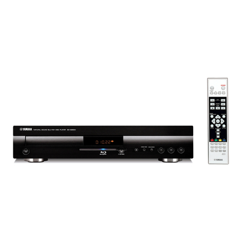
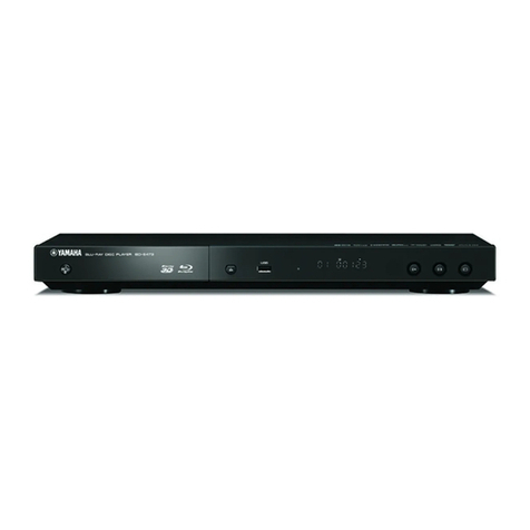
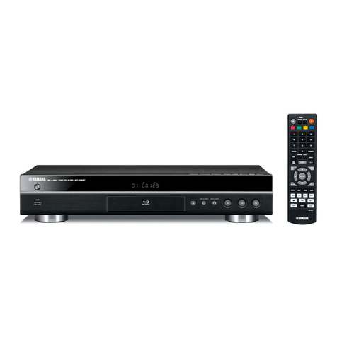
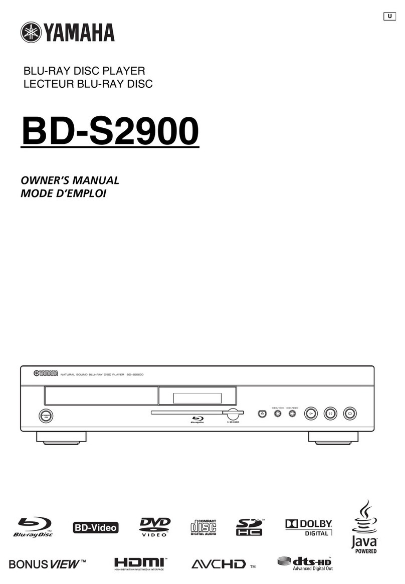
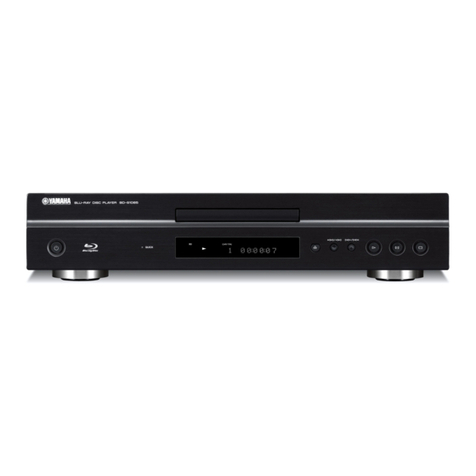
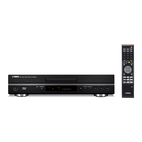
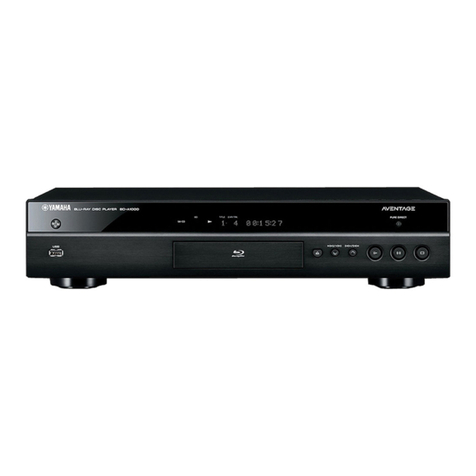
Yamaha BD-940 User manual

• When accepting a repair order from the user, it is recommended to receive BD-940 and R-840 as a set for the repair
work.
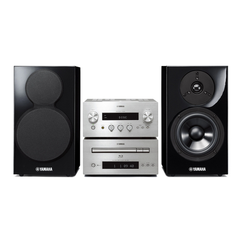
• The MCR-940 consists of the R-840, BD-940 and NS-BP300.
This service manual is for the BD-940. For service manual of the R-840/NS-BP300, please refer to the following
publication number:
R-840/NS-BP300: 101153
• When BD module P.C.B. of this unit is replaced, the serial number and new MAC address MUST be reported to Yamaha
Corporation by e-mail.
E-mail: ycav-keycontr[email protected]
For more information, refer to “SERVICE PRECAUTIONS”.
BD-940
Copyright © 2009 All rights reserved.
This manual is copyrighted by YAMAHA and may not be copied or
redistributed either in print or electronically without permission.
101154
SERVICE MANUAL
IMPORTANT NOTICE
This manual has been provided for the use of authorized YAMAHA Retailers and their service personnel.
It has been assumed that basic service procedures inherent to the industry, and more specifically YAMAHA Products, are already known
and understood by the users, and have therefore not been restated.
WARNING: Failure to follow appropriate service and safety procedures when servicing this product may result in personal injury,
destruction of expensive components, and failure of the product to perform as specified. For these reasons, we advise
all YAMAHA product owners that any service required should be performed by an authorized YAMAHA Retailer or
the appointed service representative.
IMPORTANT:The presentation or sale of this manual to any individual or firm does not constitute authorization, certification or
recognition of any applicable technical capabilities, or establish a principle-agent relationship of any form.
The data provided is believed to be accurate and applicable to the unit(s) indicated on the cover. The research, engineering, and service
departments of YAMAHA are continually striving to improve YAMAHA products. Modifications are, therefore, inevitable and
specifications are subject to change without notice or obligation to retrofit. Should any discrepancy appear to exist, please contact the
distributor's Service Division.
WARNING: Static discharges can destroy expensive components. Discharge any static electricity your body may have
accumulated by grounding yourself to the ground buss in the unit (heavy gauge black wires connect to this buss).
IMPORTANT:Turn the unit OFF during disassembly and part replacement. Recheck all work before you apply power to the unit.
■CONTENTS
TO SERVICE PERSONNEL ........................................2–3
PREVENTION OF ELECTROSTATIC DISCHARGE ......4
REGION MANAGEMENT INFORMATION .....................5
SYSTEM COMPOSITION ................................................6
FRONT PANEL ...............................................................7
REAR PANELS ...............................................................8
REMOTE CONTROL PANEL ..........................................9
SPECIFICATIONS ................................................... 10–12
INTERNAL VIEW .......................................................... 13
SERVICE PRECAUTIONS ...................................... 14–17
DISASSEMBLY PROCEDURES ............................. 18–21
UPDATING FIRMWARE ..........................................22–26
SELF-DIAGNOSTIC FUNCTION ............................27–31
DISPLAY DATA .............................................................32
IC DATA ...................................................................33–35
PIN CONNECTION DIAGRAMS .............................36–37
BLOCK DIAGRAM ........................................................39
PRINTED CIRCUIT BOARDS .................................40–44
SCHEMATIC DIAGRAMS .......................................45–48
REPLACEMENT PARTS LIST ................................49–53
REMOTE CONTROL .....................................................54
SYSTEM CONNECTOR ..........................................55–56
SETTINGS ...............................................................57–59
'09.11
P.O.Box 1, Hamamatsu, Japan
BLU-RAY DISC PLAYER
BD-940
MICRO COMPONENT SYSTEM MCR-940

2
BD-940
BD-940
This product contains chemicals known to the State of California to cause cancer, or birth defects or other reproductive
harm.
DO NOT PLACE SOLDER, ELECTRICAL/ELECTRONIC OR PLASTIC COMPONENTS IN YOUR MOUTH FOR ANY REASON
WHATSOEVER!
Avoid prolonged, unprotected contact between solder and your skin! When soldering, do not inhale solder fumes or
expose eyes to solder/flux vapor!
If you come in contact with solder or components located inside the enclosure of this product, wash your hands before
handling food.
1. Critical Components Information
Components having special characteristics are marked ⚠and
must be replaced with parts having specifications equal to those
originally installed.
2. Leakage Current Measurement (For 120V Models Only)
When service has been completed, it is imperative to verify
that all exposed conductive surfaces are properly insulated
from supply circuits.
• Meter impedance should be equivalent to 1500 ohms shunted
by 0.15 μF.
All of the P.C.B.s installed in this unit and solder joints are soldered using the lead free solder.
Among some types of lead free solder currently available, it is recommended to use one of the following types for the
repair work.
• Sn + Ag + Cu (tin + silver + copper)
• Sn + Cu (tin + copper)
• Sn + Zn + Bi (tin + zinc + bismuth)
Caution:
As the melting point temperature of the lead free solder is about 30°C to 40°C (50°F to 70°F) higher than that of the lead
solder, be sure to use a soldering iron suitable to each solder.
■TO SERVICE PERSONNEL
• Leakage current must not exceed 0.5mA.
• Be sure to test for leakage with the AC plug in both polarities.
WALL
OUTLET
EQUIPMENT
UNDER TEST
AC LEAKAGE
TESTER OR
EQUIVALENT
INSULATING
TABLE
WARNING: CHEMICAL CONTENT NOTICE!
About lead free solder
WARNING: Laser Safety
This product contains a laser beam component. This component may emit invisible, as well as visible radiation,
which may cause eye damage. To protect your eyes and skin from laser radiation, the following precautions must
be used during servicing of the unit.
1) When testing and/or repairing any component within the product, keep your eyes and skin more than 30 cm/1 feet
away from the laser pick-up unit at all times. Do not stare at the laser beam at any time.
2) Do not attempt to readjust, disassemble or repair the laser pick-up, unless noted elsewhere in this manual.
3) CAUTION: Use of controls, adjustments or performance of procedures other than those specified herein may result in
hazardous radiation exposure.
Laser Emitting conditions:
1) When the Top Cover is removed, and the STANDBY/ON SW is turned to the “ON” position, the laser component will
emit a beam for several seconds to detect if a disc is present. During this time (5-10 sec.) the laser may radiate
through the lens of the laser pick-up unit. Do not attempt any servicing during this period!
If no disc is detected, the laser will stop emitting the beam. When a disc is loaded, you will not be exposed to any
laser emissions.
2) The laser power level can be adjusted with the VR on the pick-up PWB, however, this level has been set by the factory
prior to shipping from the factory. Do not adjust this laser level control unless instruction is provided elsewhere in this
manual. Adjustment of this control can increase the laser emission level from the device.

3
BD-940
BD-940
Laser Diode Properties
Type: Class 1 LASER Product
Wavelength: CD: 788 nm
DVD: 654 nm
BD: 405 nm
Laser power: No hazardous radiation is emitted with the safety protection.
The primary side of the power supply carries live mains voltage when the player is connected to the mains even
when the player is switched off !
This primary area is not shielded so it is possible to accidentally touch copper tracks and/or components when servicing
the player.
Service personnel have to take precautions to prevent touching this area or components in this area.
Note:
The screws on the BD/DVD mechanism may never be touched, removed or re-adjusted.
Handle the BD/DVD mechanism with care when the unit has to be exchanged!
The BD/DVD mechanism is very sensitive for dropping or giving shocks.
Warning for power supply

4
BD-940
BD-940
Some semiconductor (solid state) devices can be damaged easily by static electricity. Such components commonly are
called Electrostatically Sensitive (ES) Devices. Examples of typical ES devices are integrated circuits and some field-effect
transistors and semiconductor “chip” components. The following techniques should be used to help reduce the incidence
of component damage caused by electrostatic discharge (ESD).
1. Immediately before handling any semiconductor component or semiconductor-equipped assembly, drain off any ESD
on your body by touching a known earth ground. Alternatively, obtain and wear a commercially available discharging
ESD wrist strap, which should be removed for potential shock reasons prior to applying power to the unit under test.
2. After removing an electrical assembly equipped with ES devices, place the assembly on a conductive surface such as
aluminum foil, to prevent electrostatic charge buildup or exposure of the assembly.
3. Use only a grounded-tip soldering iron to solder or unsolder ES devices.
4. Use only an anti-static solder removal device. Some solder removal devices not classified as “anti-static (ESD
protected)” can generate electrical charge sufficient to damage ES devices.
5. Do not use freon-propelled chemicals. These can generate electrical charges sufficient to damage ES devices.
6. Do not remove a replacement ES device from its protective package until immediately before you are ready to install it.
(Most replacement ES devices are packaged with leads electrically shorted together by conductive foam, aluminum foil
or comparable conductive material).
7. Immediately before removing the protective material from the leads of a replacement ES device, touch the protective
material to the chassis or circuit assembly into which the device will be installed.
CAUTION: Be sure no power is applied to the chassis or circuit, and observe all other safety precautions.
8. Minimize bodily motions when handling unpackaged replacement ES devices. (Otherwise harmless motion such as
brushing together of your fabric clothes or lifting of your foot from a carpeted floor can generate static electricity (ESD)
sufficient to damage an ES device).
Grounding for electrostatic breakdown prevention
1. Human body grounding.
Use the antistatic wrist strap to discharge the static electricity from your body.
2. Work table grounding.
Put a conductive material (sheet) or steel sheet on the area where the optical pickup is placed and ground the sheet.
Caution:
The static electricity of your clothes will not be grounded through the wrist strap. So take care not to let your clothes touch
the optical pickup.
■PREVENTION OF ELECTROSTATIC DISCHARGE
1M-ohms
Conductive material
(sheet) or steel sheet
Anti-static wrist strap

5
BD-940
BD-940
This product incorporates copyright
protection technology that is protected by
method claims of certain U.S. patents and
other intellectual property rights owned by
Macrovision Corporation and other rights
owners.
Use of this copyright protection technology
must be authorized by Macrovision
Corporation, and is intended for home
and other limited viewing uses only unless
otherwise authorized by Macrovision
Corporation.
Reverse engineering or disassembly is
prohibited.
■REGION MANAGEMENT INFORMATION
This BD/DVD player is designed and manufactured to respond to the Region Management Information that is recorded
on a BD/DVD disc. If the Region code/number described on the BD/DVD disc does not correspond to the Region code/
number of this BD/DVD player, this BD/DVD player cannot play this disc.
• BD-video Region Code
• DVD-video Region Number
A
B
B
C
A
B
1
4
2
2
2
2
5
5
4
3
6

6
BD-940
BD-940
■SYSTEM COMPOSITION
When accepting a repair order from the user, it is recommended to receive the R-840 and BD-940 as a set for the repair
work.
The MCR-940 consists of the R-840, BD-940 and NS-BP300.
This service manual is for the BD-940. For service manual of the R-840/NS-BP300, please refer to the following publication
number:
R-840/NS-BP300 : 101153
▼NS-BP300 ▼NS-BP300
▼BD-940▼R-840
MCR-940

7
BD-940
BD-940
■FRONT PANEL
B, G, F models
Front view
Top view

8
BD-940
BD-940
■REAR PANELS
B, G models
F model

9
BD-940
BD-940
■REMOTE CONTROL PANEL
B, G, F models
Key colors
A. Red
B. Green
C. Yellow
D. Blue

10
BD-940
BD-940
■Audio Section
Audio Output Level (1 kHz, 0 dB)
BD / DVD / CD-DA ............................................................2.0 ±0.3 V
Signal to Noise Ratio
BD / DVD / CD-DA ................................................... 100 dB or more
Dynamic Range (48 kHz, 24 bit)
BD / DVD / CD-DA ..................................................... 95 dB or more
Total Harmonic Distortion (1 kHz)
BD / DVD / CD-DA ....................................................0.005 % or less
Frequency Response
BD / DVD .................................. 20 Hz to 22 kHz (48 kHz sampling)
20 Hz to 44 kHz (96 kHz sampling)
CD-DA .....................................................................20 Hz to 20 kHz
■Input/Output Section
Video Output
.............................................................................. 1 Vp-p (75 ohms)
Component Video Output
Y ............................................................................ 1 Vp-p (75 ohms)
Pb, Pr ................................................................. 0.7 Vp-p (75 ohms)
Analog Audio Output Terminal
....................................................................................Mixed 2ch x 1
Digital Output Terminal
.........................................................................................Optical x 1
HDMI Output Terminal
........................................................................ Type A connector x 1
480p/576p/720p/1080i/1080p/1080p@24Hz
Deep Color
x.v. Color support
USB Terminal
Used for:
1) Playback BD-LIVE / BonusView contents
2) Software update
Other Output Terminal
............................................................... SYSTEM CONNECTOR x 1
Ethernet x 1 (for BD-LIVE)
■General
Power Supply
B, G, F models ........................................................ AC 230 V, 50 Hz
Power Consumption
.................................................................................................. 20 W
Standby Power Consumption
.........................................................................................1 W or less
Dimensions (W x H x D)
................................. 215 x 108 x 318 mm (8-1/2" x 4-1/4" x 12-1/2")
Weight
................................................................................. 3.4 kg (7.5 lbs.)
Finish
Black color ................................................................ B, G, F models
Silver color ................................................................ B, G, F models
■SPECIFICATIONS
B ......................British model
G .................European model
F .................... Russian model
Accessories
for BD-940
Remote control ...........................................................................x 1
Battery (R03, AAA, UM-4) ..........................................................x 2
Audio pin cable (1.0 m) .............................................................x 1
Video pin cable (1.5 m) ..............................................................x 1
System control cable (0.6 m) .....................................................x 1
for MCR-940 (R-840/NS-BP300)
Indoor FM antenna .....................................................................x 1
DAB wire antenna (B model) .....................................................x 1
DOCK cover ...............................................................................x 1
Speaker cable (2.0 m) ...............................................................x 2
*Specifications are subject to change without notice due to
product improvements.
“iPod” is a trademark of Apple Inc., registered in the U.S. and other
countries.
“Made for iPod” means that an electronic accessory has been designed
to connect specifically to iPod and has been certified by the developer to
meet Apple performance standards.
Apple is not responsible for the operation of this device or its compliance
with safety and regulatory standards.
Audio-visual material may consist of copyrighted works which must not
be recorded without the authority of the owner of the copyright. Refer to
relevant laws in your country.
This product incorporates copyright protection technology that is
protected by U.S. patents and other intellectual property rights.
Use of this copyright protection technology must be authorized by
Macrovision, and is intended for home and other limited viewing uses only
unless otherwise authorized by Macrovision.
Reverse engineering or disassembly is prohibited.
“BD-LIVE” logo is a trademark of Blu-ray Disc Association.
Manufactured under license from Dolby Laboratories. “Dolby” and the
double-D symbol are trademarks of Dolby Laboratories.
is a trademark.
DTS is a registered trademark and the DTS logos, Symbol, DTS-HD and
DTS-HD Master Audio | Essential are trademarks of DTS, Inc. ©1996-2008
DTS, Inc. All Rights Reserved.
11
BD-940
BD-940
Unit: mm (inch)
•DIMENSIONS
Front view
Top view
215 (8-1/2")
177 (7")
8
(3/8")
2
(1/16")
6
(1/4")
108 (4-1/4") 318 (12-1/2")
310 (12-3/16")
278 (10-7/8")
100 (3-7/8")
This product is licensed under the AVC patent portfolio license and
VC-1 patent portfolio license for the personal and noncommercial
use of a consumer to (i) encode video in compliance with the AVC
Standard and VC-1 Standard (“AVC/VC-1 Video”) and/or (ii) decode
AVC/VC-1 Video that was encoded by a consumer engaged in a
personal and non-commercial activity and/or was obtained from a
video provider licensed to provide AVC/VC-1 Video. No license is
granted or shall be implied for any other use. Additional information
may be obtained from MPEG LA, LLC.
HDMI, the HDMI logo and High-Definition Multimedia Interface are
trademarks or registered trademarks of HDMI Licensing LLC.
“AVCHD” and the “AVCHD” logo are trademarks of Panasonic Corporation
and Sony Corporation.
“BONUSVIEW” is a trademark of Blu-ray Disc Association.
“x.v.Color” and “x.v.Color” logo are trademarks.
is a trademark of DVD Format/Logo Licensing Corporation.
Java and all Java-based trademarks and logos are trademarks or
registered trademarks of Sun Microsystems, Inc. in the United States and/
or other countries.

12
BD-940
BD-940
•SET MENU TABLE
MAIN MENU SUB-MENU PARAMETER VALUE [INITIAL VALUE]
Audio Video Settings TV Aspect Ratio [Wide 16:9] / Normal 4:3
Normal 4:3 [Letter Box] / Pan Scan
Component Video Out 1080i / 720p / 576/480p / [576/480i]
HDMI Video Out [Auto] / 1080p / 1080i / 720p / 576/480p
Video Out Select [HDMI] / Component
Secondary Audio [On] / Off
Audio Out HDMI Output / Digital Output / [2ch Audio Output]
HDMI Output Bitstream / [PCM (Surround)]
Digital Output Bitstream / [PCM]
Dynamic Range Control Normal / Shift / [Auto]
Quick Start Yes / [No]
Auto Power Off Yes / [No]
HDMI Control Yes / [No]
Playback Setting Parental Control Yes / [No]
DVD [Level 8 and Off] / Level 1-7
BD [No Limit] / 0-99 year(s)
Disc Language (Disc Priority Language) Select the language for subtitles, audio and menus displayed on the screen.
Angle Mark Display Yes / [No]
PIN Code Setting Yes (Sets the password) / [No (Does not set a password)]
BD Internet Access Permit / [Limit] / Prohibit
Communication Setup Ethernet Setup (BD-LIVE)
Version Version : xxxxxxxxx
USB Memory Management
Software Update
System Reset Reset / Not Reset

13
BD-940
BD-940
■INTERNAL VIEW
Top view
Front view
Rear view
BD MODULE P.C.B.
MAIN (4) P.C.B.
POWER P.C.B.
MAIN (2) P.C.B.
BD MECHANISM UNIT
MAIN (1) P.C.B.
MAIN (3) P.C.B.
1
2
3
4
5
6
7
4
7
12
3
56

14
BD-940
BD-940
■SERVICE PRECAUTIONS
When BD module P.C.B. is replaced, the serial number and MAC address MUST be reported to Yamaha Corporation by
e-mail. (Fig. 1)
E-mail: ycav-keycontr[email protected]
●Check the Serial Number
The serial number “SER.No.xxxxxxx” can be found at the rear panel of this unit. (Fig. 2)
Fig. 1
Fig. 2
Rear view Serial number
xxxxxxxxx
Send this e-mail to Yamaha Corporation
BD-940
xxxxxxxxx
Model name
Serial number
New MAC address

15
BD-940
BD-940
●Check the New MAC Address
Connection
1. Connect the SYSTEM CONNECTOR terminal of the BD-940 to the SYSTEM CONNECTOR terminal of the R-840
with a system control cable. (Fig. 3)
2. Connect the VIDEO OUT terminal of the BD-940 to the VIDEO IN terminal of the TV with a video pin cable. (Fig. 3)
Operation Procedure
Perform the following steps while watching the TV monitor screen and using the keys on the remote control.
1. With this unit in the standby mode, press the “ ” (On/Standby) key of this unit to turn on the power.
2. Set this unit to the Communication Setup mode by procedure below.
Press the “SETUP” key => Select the Setting menu => Select the Communication Setup menu
Fig. 3
System control cable
This unit (BD-940) TV monitor
R-840
Video pin cable
Audio Video Settings
Quick Start
Auto Power Off
HDMI Control
Playback Setting
Communication Setup
Version
USB Memory Management
Software Update
System Reset
Displays The Title List
On Screen Language
Settings
Picture
Setup menu
Setting menu
This unit
Remote control
" "(On/Standby) key
"SETUP" key
"ENTER" key
" " (DOWN) key
" " (RIGHT) key

16
BD-940
BD-940
This allows you to perform and/or change the
communication setting. This setting is required to use
BD-LIVE functions that connect to the internet.
Notes
• Make sure that the LAN cable is connected to this
Player.
• For manually performing the setting, the following
information of the connected router or modem
is required. Confirm the information prior to the
setting.
– IP address, netmask, gateway, DNS IP address
• Besides, if specifying a proxy server, the following
information specified from your internet service
provider is also required.
Confirm the information prior to the setting.
– IP address and port number of the proxy server
Communication Setup
5 Press / to select “Change”, then press
ENTER.
For initializing the current setting, select “Initialize”,
then press ENTER.
6 For setting the IP address, press / to
select “Yes” or “No”, then press ENTER.
• If selecting “Yes”:
The IP address is automatically obtained.
• If selecting “No”:
The IP address, netmask and gateway
are manually entered using the screen for
inputting characters.
Regarding each of the setup values, confirm
the specifications of your broadband router.
7 Select “Next”, then press ENTER.
8 Enter the primary and secondary IP addresses
using the screen for inputting characters.
Regarding each of the setup values, confirm
the specifications of your broadband router.
9 Select “Next”, then press ENTER.
Remote control
1 Press SETUP.
2 Press / / / to select “Settings”,
then press ENTER.
3 Press / to select “Communication
Setup”, then press ENTER.
4 Select “Ethernet Setup (BD-LIVE)”, then
press ENTER.
"SETUP" key
" " (DOWN) key
" " (UP) key
" " (LEFT) key
"ENTER" key
" " (RIGHT) key
Setting the info. of the Ethernet
[Current Setup]
IP Address : Auto Setup
Netmask : Auto Setup
Gateway : Auto Setup
DNS : Auto Setup
Proxy : Not Use
InitializeChange
No
Next
Yes
Do you obtain the IP address
automatically?
IP Address
Netmask
Gateway

17
BD-940
BD-940
10 For setting the proxy server, press /
to select “Yes” or “No”, then press ENTER.
14 Press / to select “Complete”, then
press ENTER.
13 For testing the connection to the internet,
after confirming the settings, press /
to select “Test”, then press ENTER.
“Test” is available only when setting to obtain the
IP address automatically.
• If selecting “Yes”:
The IP address or proxy server name and port
number for the proxy server specified from
your internet service provider are entered
using the screen for inputting characters.
• If selecting “No”:
Go to the next step.
11 Select “Next”, then press ENTER.
12 For the advanced setting (the setting of
the Ethernet connection speeds), press
/ to select “Yes” or “No”, then press
ENTER.
• Normally select “No”, then press ENTER.
• The Ethernet connection speeds can be set
when you select “Yes”, then press ENTER.
• As automatic detection is made (factory preset
mode), this setting is not normally necessary.
If a situation occurs in which the Ethernet
connection fails, etc., change the setting and
confirm if the Ethernet connection successfully
works.
When the connection speed is set, select
“Next”, then press ENTER.
Next
NoYes
Do you use the proxy server?
Address
Port
Next
Option
Ethernet Connection Speeds
Auto-Detection
10M Half Duplex 10M Full Duplex
100M Full Duplex100M Half Duplex
Confirm the current setting.
IP Address : xxx xxx xxx xxx
Netmask : xxx xxx xxx xxx
Gateway : xxx xxx xxx xxx
DNS Address : xxx xxx xxx xxx
xxx xxx xxx xxx
MAC Address : xx:xx:xx:xx:xx:xx
CompleteTest
New MAC address will appear on
the TV screen as shown above.

18
BD-940
BD-940
CB200
MAIN (1) P.C.B.
Top cover
Front panel unit
W601
Hook
Hook
122
2
1
3
3
5
4
■DISASSEMBLY PROCEDURES
(Remove parts in disassembly order as numbered.)
Disconnect the power cable from the AC outlet.
1. Removal of Top Cover
a. Remove 4 screws (①) and 4 screws (②). (Fig. 1)
b. Slide the top cover rearward to remove it. (Fig. 1)
2. Removal of Front Panel Unit
a. Remove 2 screws (③) and 2 screws (④). (Fig. 1)
b. Remove screw (⑤) and remove W601. (Fig. 1)
c. Remove CB200. (Fig. 1)
d. Release 2 hooks and remove the front panel unit.
(Fig. 1)
Fig. 1

19
BD-940
BD-940
CB401 CB803
CB201
TE1
CB202
CB205
CB204
MAIN (2) P.C.B.
MAIN (1) P.C.B.
Chassis
POWER P.C.B.
8
8
6
10
7
9
7
7
9
BD mechanism unit
Rear panel unit
Fig. 2
3. Removal of POWER and MAIN (1) P.C.B.s
a. Remove 2 screws (⑥). (Fig. 2)
b. Remove 2 screws (⑦). (Fig. 2)
c. Remove CB201–202, CB204–205, CB401, CB803
and TE1. (Fig. 2)
d. Remove the POWER P.C.B. together with the MAIN (1)
P.C.B.. (Fig. 2)
4. Removal of Rear Panel Unit
a. Remove 3 screws (⑧). (Fig. 2)
b. Remove 2 screws (⑨). (Fig. 2)
c. Remove 2 screws (⑩). (Fig. 2)
d. Remove the rear panel unit together with the BD
mechanism unit. (Fig. 2)

20
BD-940
BD-940
Use a clip or other item to ground
the unit.
SC3002
Clip
Terminal side
23 mm
(15/16")
BD Module P.C.B.
CN3001
SC3002 SC5601
BD mechanism unit
Rear panel unit
11
11
12 12
13
13
5. Removal of BD Mechanism Unit
a. Remove 4 screws (⑪). (Fig. 3)
b. Unlock and remove CN3001. (Fig. 3)
c. Unlock and remove SC3002, and ground the terminal
face of the flexible flat cable with a clip or the like.
(Fig. 3)
d. Remove the BD mechanism unit. (Fig. 3)
6. Removal of BD Module P.C.B.
a. Remove 3 screws (⑫). (Fig. 3)
b. Remove 2 screws (⑬). (Fig. 3)
c. Remove SC5601. (Fig. 3)
d. Remove the BD Module P.C.B.. (Fig. 3)
Bottom side
Manual eject lever BD mechanism unit
Disc tray
Screwdriver
Fig. 3
• How to manually eject the disc tray
a. Remove the top cover and front panel unit. (Fig. 1)
b. Press the manual eject lever with screwdriver until the disc tray is ejected. (Fig. 4)
c. Gently pull the disc tray out.
Fig. 4
Table of contents
Other Yamaha Blu-ray Player manuals

Yamaha
Yamaha BD-S1900 User manual

Yamaha
Yamaha BD-S667 User manual

Yamaha
Yamaha BRX-610 User manual

Yamaha
Yamaha BD-S2900 - Blu-Ray Disc Player User manual

Yamaha
Yamaha BD-S673 User manual

Yamaha
Yamaha BD-S1065 Instruction Manual

Yamaha
Yamaha BD-S1065 User manual

Yamaha
Yamaha BD-S671BL User manual

Yamaha
Yamaha BD-S667 User manual

Yamaha
Yamaha BD-S677 User manual

Yamaha
Yamaha BD-S673 User manual

Yamaha
Yamaha BRX-610 User manual

Yamaha
Yamaha BD-S1065 User manual

Yamaha
Yamaha AVENTAGE BD-A1060 User manual

Yamaha
Yamaha BD-S677 User manual

Yamaha
Yamaha BD-A1020 User manual

Yamaha
Yamaha BD-A1000 User manual

Yamaha
Yamaha BD-A1010 User manual

Yamaha
Yamaha 80-51065 User manual

Yamaha
Yamaha BD-A1010 User manual