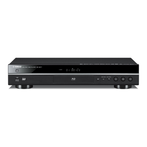
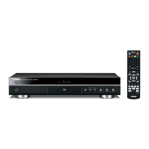
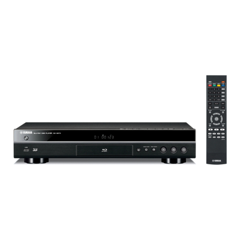
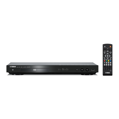
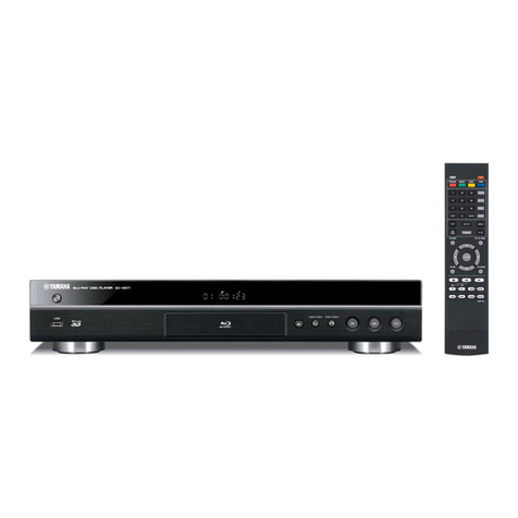
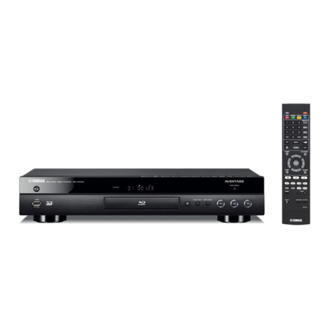
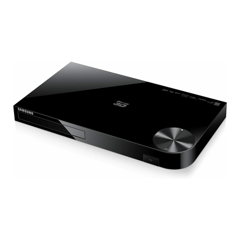
Yamaha BD-S677 User manual

P.O.Box 1, Hamamatsu, Japan
'14.04
Copyright (c) Yamaha Corporation All rights reserved.
This manual is copyrighted by Yamaha and may not be copied or
redistributed either in print or electronically without permission.
101298
SERVICE MANUAL
■CONTENTS
TO SERVICE PERSONNEL ........................................2–4
PREVENTION OF ELECTROSTATIC DISCHARGE ......5
REGION MANAGEMENT INFORMATION .....................6
FRONT PANEL ...............................................................7
REAR PANELS ...........................................................7–9
REMOTE CONTROL PANELS ..................................... 10
SPECIFICATIONS ................................................... 11–12
INTERNAL VIEW ..........................................................13
SERVICE PRECAUTIONS ...................................... 14–16
DISASSEMBLY PROCEDURES ............................. 17–18
REWRITING OPU PARAMETER ............................19–25
FRONT PANEL KEYS LOCK MODE ............................26
BLOCK DIAGRAM ........................................................27
WIRING DIAGRAM .......................................................28
PRINTED CIRCUIT BOARDS .................................29–30
SCHEMATIC DIAGRAMS .......................................31–42
REPLACEMENT PARTS LIST ................................44–45
REMOTE CONTROL ...............................................46–47
SETUP MENU ...............................................................48
SOFTWARE UPGRADE ...............................................49
BLU-RAY DISC PLAYER
BD-S677
*When the MAIN P.C.B. or Wi-Fi module is replaced, the serial number, new MAC (Wired) address and new
MAC (Wireless) address MUST be reported to Yamaha Corporation by e-mail.
E-mail: ycav-keycontr[email protected]
For more information, refer to “SERVICE PRECAUTIONS”.
IMPORTANT NOTICE
This manual has been provided for the use of authorized Yamaha Retailers and their service personnel.
It has been assumed that basic service procedures inherent to the industry, and more specifically Yamaha Products, are already known
and understood by the users, and have therefore not been restated.
WARNING: Failure to follow appropriate service and safety procedures when servicing this product may result in personal injury,
destruction of expensive components, and failure of the product to perform as specified. For these reasons, we advise
all Yamaha product owners that any service required should be performed by an authorized Yamaha Retailer or the
appointed service representative.
IMPORTANT: The presentation or sale of this manual to any individual or firm does not constitute authorization, certification or
recognition of any applicable technical capabilities, or establish a principle-agent relationship of any form.
The data provided is believed to be accurate and applicable to the unit(s) indicated on the cover. The research, engineering, and service
departments of Yamaha are continually striving to improve Yamaha products. Modifications are, therefore, inevitable and specifications
are subject to change without notice or obligation to retrofit. Should any discrepancy appear to exist, please contact the distributor's
Service Division.
WARNING: Static discharges can destroy expensive components. Discharge any static electricity your body may have
accumulated by grounding yourself to the ground buss in the unit (heavy gauge black wires connect to this buss).
IMPORTANT: Turn the unit OFF during disassembly and part replacement. Recheck all work before you apply power to the unit.
BD-S677
This product contains chemicals known to the State of California to cause cancer, or birth defects or other reproductive
harm.
DO NOT PLACE SOLDER, ELECTRICAL/ELECTRONIC OR PLASTIC COMPONENTS IN YOUR MOUTH FOR ANY REASON
WHATSOEVER!
Avoid prolonged, unprotected contact between solder and your skin! When soldering, do not inhale solder fumes or
expose eyes to solder/flux vapor!
If you come in contact with solder or components located inside the enclosure of this product, wash your hands before
handling food.
1. Critical Components Information
Components having special characteristics are marked ⚠and
must be replaced with parts having specifications equal to those
originally installed.
2. Leakage Current Measurement (For 120V Models Only)
When service has been completed, it is imperative to verify
that all exposed conductive surfaces are properly insulated
from supply circuits.
• Meter impedance should be equivalent to 1500 ohms shunted
by 0.15 μF.
■TO SERVICE PERSONNEL
• Leakage current must not exceed 0.5mA.
• Be sure to test for leakage with the AC plug in both polarities.
WARNING: CHEMICAL CONTENT NOTICE!
All of the P.C.B.s installed in this unit and solder joints are soldered using the lead free solder.
Among some types of lead free solder currently available, it is recommended to use one of the following types for the
repair work.
• Sn + Ag + Cu (tin + silver + copper)
• Sn + Cu (tin + copper)
• Sn + Zn + Bi (tin + zinc + bismuth)
Caution:
As the melting point temperature of the lead free solder is about 30°C to 40°C (50°F to 70°F) higher than that of the lead
solder, be sure to use a soldering iron suitable to each solder.
About lead free solder
WALL
OUTLET
EQUIPMENT
UNDER TEST
AC LEAKAGE
TESTER OR
EQUIVALENT
INSULATING
TABLE
2
BD-S677
BD-S677
BD-S677
WARNING: Laser Safety
This product contains a laser beam component. This component may emit invisible, as well as visible radiation,
which may cause eye damage. To protect your eyes and skin from laser radiation, the following precautions must
be used during servicing of the unit.
1) When testing and/or repairing any component within the product, keep your eyes and skin more than 30 cm/1 feet
away from the laser pick-up unit at all times. Do not stare at the laser beam at any time.
2) Do not attempt to readjust, disassemble or repair the laser pick-up, unless noted elsewhere in this manual.
3) CAUTION: Use of controls, adjustments or performance of procedures other than those specified herein may result in
hazardous radiation exposure.
Laser Emitting conditions:
1) When the Top Cover is removed, and the STANDBY/ON SW is turned to the “ON” position, the laser component will
emit a beam for several seconds to detect if a disc is present. During this time (5-10 sec.) the laser may radiate
through the lens of the laser pick-up unit. Do not attempt any servicing during this period!
If no disc is detected, the laser will stop emitting the beam. When a disc is loaded, you will not be exposed to any
laser emissions.
2) The laser power level can be adjusted with the VR on the pick-up PWB, however, this level has been set by the factory
prior to shipping from the factory. Do not adjust this laser level control unless instruction is provided elsewhere in this
manual. Adjustment of this control can increase the laser emission level from the device.
Type: Class 1 LASER Product
Wavelength: CD: 790 nm
DVD: 658 nm
BD: 405 nm
Laser output: max. 1 mW
Laser Diode Properties
3
BD-S677
ADVARSEL
Usynlig laserstråling ved åbning. Undgå udsaettelse for
stråling.
VARNING
Om apparaten används på annat sätt än i denna
bruksanvisning specificerats, kan användaren utsättas
för osynlig laserstrålning, som överskrider gränsen för
laserklass 1.
VAROITUS
Laitteen käyttäminen muulla kuin tässä käyttöohjeesa
mainitulla tavalla saattaa altistaa käyttäjän
turvallisuusluokan 1 ylittävälle näkymättömälle
lasersäteilylle.
CAUTION
Use of controls or adjustments or performance of
procedures other than those specified herein may result
in hazardous radiation exposure.
AVERTISSEMENT
L’utilisation de commandes et l’emploi de réglages ou
de méthodes autres que ceux décrits ci-dessous,
peuvent entraîner une exposition à un rayonnement
dangereux.
VORSICHT
Die Verwendung von Bedienelementen oder die
Einstellung bzw. die Ausführung von anderen als in
dieser Anleitung beschriebenen Vorgängen kann zu
Gefährdung durch gefährliche Strahlung führen.
OBSERVERA
Användning av reglage eller justeringar eller utförande
av åtgärder på annat sätt än så som beskrivs häri kan
resultera i farlig strålning.
ATTENZIONE
L’uso di controlli, regolazioni, operazioni o procedure
non specificati in questo manuale possono risultare in
esposizione a radiazioni pericolose.
PRECAUCIÓN
El uso de los controles, los ajustes o los procedimientos
que no se especifican enste manual pueden causar una
exposición peligrosa a la radiación.
LET OP
Gebruik van bedieningsorganen, instellingen of
procedures anders dan beschreven in dit document kan
leiden tot blootstelling aan gevaarlijke stralen.
VAROITUS
Muiden kuin tässä esitettyjen toimintojen säädön tai
asetusten muutto saattaa altistaa vaaralliselle säteilylle
tai muille vaarallisille toiminnoille.
VARO!
AVATTAESSA JA SUOJALUKITUS
OHITETTAESSA OLET ALTTIINA
NÄKYMÄTTÖMÄLLE LASERSÄTEILYLLE.
ÄLÄ KATSO SÄ TEESEEN.
VARNING!
OSYNLIG LASERSTRÅLNING NÄR DENNA DEL
ÄR ÖPPNAD OCH SPÄRREN ÄR URKOPPLAD.
BETRAKTA EJ STRÅLEN.
CAUTION:
INVISIBLE LASER RADIATION WHEN OPEN.
AVOID DIRECT EXPOSURE TO THE BEAM.
DO NOT STARE INTO BEAM.
DANGER:
INVISIBLE LASER RADIATION WHEN OPEN.
The primary side of the power supply carries live mains voltage when the player is connected to the mains even
when the player is switched off !
This primary area is not shielded so it is possible to accidentally touch copper tracks and/or components when servicing
the player.
Service personnel have to take precautions to prevent touching this area or components in this area.
Note:
The screws on the BD/DVD mechanism may never be touched, removed or re-adjusted.
Handle the BD/DVD mechanism with care when the unit has to be exchanged!
The BD/DVD mechanism is very sensitive for dropping or giving shocks.
Warning for power supply
4
BD-S677
BD-S677
BD-S677
Some semiconductor (solid state) devices can be damaged easily by static electricity. Such components commonly are
called Electrostatically Sensitive (ES) Devices. Examples of typical ES devices are integrated circuits and some field-effect
transistors and semiconductor “chip” components. The following techniques should be used to help reduce the incidence
of component damage caused by electrostatic discharge (ESD).
1. Immediately before handling any semiconductor component or semiconductor-equipped assembly, drain off any ESD
on your body by touching a known earth ground. Alternatively, obtain and wear a commercially available discharging
ESD wrist strap, which should be removed for potential shock reasons prior to applying power to the unit under test.
2. After removing an electrical assembly equipped with ES devices, place the assembly on a conductive surface such as
aluminum foil, to prevent electrostatic charge buildup or exposure of the assembly.
3. Use only a grounded-tip soldering iron to solder or unsolder ES devices.
4. Use only an anti-static solder removal device. Some solder removal devices not classified as “anti-static (ESD
protected)” can generate electrical charge sufficient to damage ES devices.
5. Do not use freon-propelled chemicals. These can generate electrical charges sufficient to damage ES devices.
6. Do not remove a replacement ES device from its protective package until immediately before you are ready to install it.
(Most replacement ES devices are packaged with leads electrically shorted together by conductive foam, aluminum foil
or comparable conductive material).
7. Immediately before removing the protective material from the leads of a replacement ES device, touch the protective
material to the chassis or circuit assembly into which the device will be installed.
CAUTION: Be sure no power is applied to the chassis or circuit, and observe all other safety precautions.
8. Minimize bodily motions when handling unpackaged replacement ES devices. (Otherwise harmless motion such as
brushing together of your fabric clothes or lifting of your foot from a carpeted floor can generate static electricity (ESD)
sufficient to damage an ES device).
Grounding for electrostatic breakdown prevention
1. Human body grounding.
Use the antistatic wrist strap to discharge the static electricity from your body.
2. Work table grounding.
Put a conductive material (sheet) or steel sheet on the area where the optical pickup is placed and ground the sheet.
Caution:
The static electricity of your clothes will not be grounded through the wrist strap. So take care not to let your clothes touch
the optical pickup.
■PREVENTION OF ELECTROSTATIC DISCHARGE
1M-ohms
Conductive material
(sheet) or steel sheet
Anti-static wrist strap
5
BD-S677

This product incorporates copyright
protection technology that is protected by
method claims of certain U.S. patents and
other intellectual property rights owned by
Macrovision Corporation and other rights
owners.
Use of this copyright protection technology
must be authorized by Macrovision
Corporation, and is intended for home
and other limited viewing uses only unless
otherwise authorized by Macrovision
Corporation.
Reverse engineering or disassembly is
prohibited.
■REGION MANAGEMENT INFORMATION
This BD/DVD player is designed and manufactured to respond to the Region Management Information that is recorded
on a BD/DVD disc. If the Region code/number described on the BD/DVD disc does not correspond to the Region code/
number of this BD/DVD player, this BD/DVD player cannot play this disc.
• BD-video Region Code
• DVD-video Region Number
A
B
B
C
A
B
1
4
2
2
2
2
5
5
4
3
6
6
BD-S677
BD-S677

BD-S677
■FRONT PANEL
U model
C model
T model
■REAR PANELS
7
BD-S677

K model
A model
B model
G model
F model
8
BD-S677
BD-S677

BD-S677
L model
V model
S model
P model
9
BD-S677

■REMOTE CONTROL PANELS
BDP124
U model
BDP125
C, K, A, B, G, F, L, V, S, P models
BDP123
T model
ZOOM: Red
PROGRAM: Green
SHUFFLE: Yellow
REPEAT: Blue
10
BD-S677
BD-S677

BD-S677
■SPECIFICATIONS
■Audio Section
Audio Output Level (1 kHz, 0 dB)
BD / DVD / CD-DA ............................................................2.0 ±0.3 V
Signal to Noise Ratio
BD / DVD / CD-DA .................................................................115 dB
Dynamic Range (1 kHz, 0 dB)
BD / DVD ...............................................................................105 dB
CD-DA ...................................................................................100 dB
Total Harmonic Distortion (1 kHz)
BD / DVD / CD-DA ............................................................... 0.003 %
Frequency Response
BD / DVD .................................... 4 Hz to 22 kHz (48 kHz sampling)
4 Hz to 44 kHz (96 kHz sampling)
CD-DA .......................................................................4 Hz to 20 kHz
■Input/Output Section
HDMI Output Terminal ..................................... Type A connector x 1
480i/576i/480p/576p/720p/1080i/1080p/1080p@24Hz,
Deep Color, x.v. Color support
Digital Output Terminal .................................................OPTICAL x 1
COAXIAL x 1
Analog Audio Output Terminal ....................................... L/R 2ch x 1
USB Terminal ......................Type A connector x 2 (Front x1, Rear x1)
Wireless LAN .........................................Standard: IEEE 802.11 b/g/n
Frequency range: 2.4GHz band
Channels 1–11 (U, C, V models)
Other Output Terminal ....................REMOTE CONTROL IN/OUT x 1
NETWORK x 1
■General
Power Supply
U, C, K, V, S models ........................................ AC 110–240 V, 60 Hz
T, A, B, G, F models ........................................ AC 110–240 V, 50 Hz
L, P models ................................................ AC 110–240 V, 50/60 Hz
Power Consumption .................................................................. 17 W
Standby Power Consumption
HDMI control: OFF / NETWORK standby: OFF .......... 0.2 W (typical)
HDMI control: ON / NETWORK standby: OFF ........... 0.3 W (typical)
HDMI control: OFF / NETWORK standby: ON ........... 5.5 W (typical)
HDMI control: ON / NETWORK standby: ON ............ 5.5 W (typical)
Dimensions (W x H x D)
................................. 435 x 86 x 257 mm (17-1/8" x 3-3/8" x 10-1/8")
Weight ........................................................................ 2.7 kg (6.0 lbs.)
Finish
U, C, T, K, A, B, G, F, L, V, S, P models ........................... Black color
G, F models ................................................................Titanium color
Accessories
Remote control ..............................................................................x 1
Battery (R03, AAA, UM-4) .............................................................x 2
Power cable (1.5 m) .....................................................................x 1
*Specifications are subject to change without notice.
U .......................U.S.A. model
C .................Canadian model
T .................... Chinese model
K ..................... Korean model
A ................Australian model
B ......................British model
G .................European model
F .................... Russian model
L .................Singapore model
V ..................... Taiwan model
S .................. Brazilian model
P ........Latin American model
“Blu-ray Disc™”, “Blu-ray™”, “Blu-ray 3D™”, “BD-Live™”, “BONUSVIEW™”,
and the logos are trademarks of the Blu-ray Disc Association.
Manufactured under license from Dolby Laboratories. Dolby and the
double-D symbol are trademarks of Dolby Laboratories.
DTS-HD, the Symbol, & DTS-HD and the Symbol together are registered
trademarks & DTS-HD Master Audio is a trademark of DTS, Inc.
Product includes software. © DTS, Inc. All Rights Reserved.
“HDMI,” the “HDMI” logo and High-Definition Multimedia Interface are
trademarks or registered trademarks of HDMI Licensing LLC in the United
States and other countries.
“AVCHD” and the “AVCHD” logo are trademarks of Panasonic Corporation
and Sony Corporation.
DLNA™ and DLNA CERTIFIED™ are trademarks or registered trademarks
of Digital Living Network Alliance. All rights reserved. Unauthorized use is
strictly prohibited.
The Wi-Fi CERTIFIED Logo is a certification mark of the Wi-Fi Alliance.
The Wi-Fi Protected Setup Identifier Mark is a mark of the Wi-Fi Alliance.
“Wi-Fi”, “Wi-Fi Protected Setup”, “Wi-Fi Direct” and “Miracast” are marks or
registered marks of the Wi-Fi Alliance.
Java is a registered trademark of Oracle and/or its affiliates.
“x.v.Color” and “x.v.Color” logo are trademarks of Sony Corporation.
is a trademark of DVD Format/Logo Licensing Corporation.
– This product is licensed under the AVC patent portfolio license and
VC-1 patent portfolio license for the personal and non-commercial use
of a consumer to (i) encode video in compliance with the AVC Standard
and VC-1 Standard (“AVC/VC-1 Video”) and/or (ii) decode AVC/VC-1
Video that was encoded by a consumer engaged in a personal and non-
commercial activity and/or was obtained from a video provider licensed
to provide AVC/VC-1 Video. No license is granted or shall be implied for
any other use. Additional information may be obtained from MPEG LA,
LLC.
11
BD-S677

ø 60
435 (17-1/8")
50
(2")
335 (13-1/4")
147 (5-13/16")55
(2-1/8")
47
(1-7/8")
257 (10-1/8")86 (3-3/8")
249 (9-13/16")70 (2-3/4")16
(5/8")
1
(1/16")
7
(1/4")
•DIMENSIONS
Unit: mm (inch)
– This product is licensed under the MVC patent portfolio license for the
personal use of a consumer or other uses in which it does not receive
remuneration to (i) encode video in compliance with the MVC Standard
(“MVC Video”) and/or (ii) decode MVC Video that was encoded by a
consumer engaged in a personal activity and/or was obtained from a
video provider licensed to provide MVC Video. No license is granted
or shall be implied for any other use. Additional information may be
obtained from MPEG LA, LLC.
– Copyright 2004-2012 Verance Corporation. Cinavia® is a Verance
Corporation trademark. Protected by U.S. Patent 7,369,677 and worldwide
patents issued and pending under license from Verance Corporation. All
rights reserved.
– Windows Media Player is a registered trademark or trademark of Microsoft
corporation in the United States and/or other countries.
ABOUT DIVX VIDEO: DivX® is a digital video format created by DivX,
LLC, a subsidiary of Rovi Corporation. This is an official DivX Certified®
device that has passed rigorous testing to verify that it plays DivX video.
Visit divx.com for more information and software tools to convert your
files into DivX videos.
ABOUT DIVX VIDEO-ON-DEMAND: This DivX Certified® device must
be registered in order to play purchased DivX Video-on-Demand (VOD)
movies. To obtain your registration code, locate the DivX VOD section in
your device setup menu. Go to vod.divx.com for more information on how
to complete your registration.
DivX®, DivX Certified®, DivX Plus® HD and associated logos are trademarks
of Rovi Corporation or its subsidiaries and are used under license.
DivX Certified® to play DivX® and DivX Plus® HD (H.264/.MKV) video up
to 1080p HD including premium content.
12
BD-S677
BD-S677

BD-S677
1
2
3
4
5
6
7
1
765
243
POWER SUPPLY UNIT
BD MECHANISM UNIT
IR P.C.B.
MAIN P.C.B.
Wi-Fi MODULE
CONTROL P.C.B.
USB P.C.B.
■INTERNAL VIEW
13
BD-S677

This unit
TV monitor
HDMI input
HDMI cable
HDMI output
Serial number
Rear view
Fig. 1
Fig. 2
Fig. 3
<Confirmation of the Serial Number>
The serial number “SERIAL NO. xxxxxxx” can be found on the rear panel. (Fig. 2)
<Confirmation of the New MAC (Wired) address and New MAC (Wireless) address>
Connection
Connect a TV monitor to this unit as shown below. (Fig. 3)
■SERVICE PRECAUTIONS
●Report of serial number and MAC address
When the MAIN P.C.B. or Wi-Fi module is replaced, the serial number, new MAC (Wired) address and new MAC (Wireless)
address MUST be reported to Yamaha Corporation by e-mail. (Fig. 1)
E-mail: ycav-keycontr[email protected]
xxxxxxxxx
Send this e-mail to Yamaha Corporation
BD-S677
xxxxxxxxx
Model name
Serial number
New MAC (Wired) address
New MAC (Wireless) address
xxxxxxxxx
14
BD-S677
BD-S677

BD-S677
No Disc
SETUP menu screenInitial screenRemote control
U model
“SETUP” key
C, K, A, B, G, F, L, V, S, P models
“SETUP” key
Return
RETURN
Operation Procedure
Using the remote control, perform the following procedure while watching the TV monitor screen.
1. With this unit in the standby mode, press the “ ” (On/Standby) key to turn on the power.
The initial screen is displayed.
U, C, K, A, B, G, F, L, V, S, P models
T model
2. Press the “SETUP” key.
The SETUP menu is displayed. (Fig. 4)
2. Press the “HOME” key.
Press the “ ”/“ ” key to select the SETUP menu. (Fig. 5)
Fig. 4
Fig. 5
No Disc
Initial screen HOME menu screen
SETUP menu screen
Remote control
Return
RETURN
“HOME” key
Exit
HOMEItem 5 / 5
BDMV Type:Unknown
USB1
DLNA
SETUP
Network Services
HOME
15
BD-S677

Software Version : x.xxxMxxxx
MAC (Wired): 00-A0-DE-xx-xx-xx
MAC (Wireless): 64-51-7E-xx-xx-xx
--- System Information ---
SETUP menu screen
New MAC (Wired) address
New MAC (Wireless) address
Select the System Information
Fig. 6
3. Press the “ ”/“ ” key to select the System Information.
The new MAC (Wired) address and new MAC (Wireless) address are displayed. (Fig. 6)
16
BD-S677
BD-S677

BD-S677
Hole
Slider
Allen hex socket screwdriver
(size: 1.3 mm or .050")
Disc tray
Bottom side
Top cover
BD mechanism unit
Flexible flat cable
HA3
HA2
J15
MAIN P.C.B. Use a clip or other item to ground
the unit.
Clip
Terminal side
23 mm
(15/16")
HA3
①
②
③
①
③
Fig. 1
■DISASSEMBLY PROCEDURES
(Remove parts in the order as numbered.)
Disconnect the power cable from the AC outlet.
1. Removal of Top Cover
a. Remove 2 screws (①) and 4 screws (②). (Fig. 1)
b. Slide the top cover rearward to remove it. (Fig. 1)
2. Removal of BD Mechanism Unit
a. Remove 4 screws (③). (Fig. 1)
b. Remove HA2, HA3 and J15. (Fig. 1)
c. Remove the BD mechanism unit. (Fig. 1)
•How to manually eject the disc tray
a. Using an Allen hex socket screwdriver (size: 1.3 mm
or .050"), move the slider at the bottom side in the
direction of the arrow as shown below until the disc
tray comes out. (Fig.2)
b. Gently pull the disc tray out. (Fig. 2)
Fig. 2
17
BD-S677

Top case
④④
Loading belt
Disc tray
Hook
Hook
Hook
Front panel unit Hook
CONTROL P.C.B.
Wi-Fi module
MAIN P.C.B.
J305
J304
CN2
J410
⑤
⑥
⑦
⑤
2-1. Removal of Loading Belt
a. Remove 2 screws (④). (Fig. 3)
b. Release 2 hooks and remove the top case. (Fig. 3)
c. Eject the disc tray and remove the loading belt. (Fig. 3)
3. Removal of Front Panel Unit
a. Remove 3 screws (⑤), 3 screws (⑥) and 2 screws (⑦). (Fig. 4)
b. Remove CN2, J304, J305 and J410. (Fig. 4)
c. Release 2 hooks and remove the front panel unit. (Fig. 4)
Fig. 3
Fig. 4
18
BD-S677
BD-S677

BD-S677
■REWRITING OPU PARAMETER
*OPU stands for Optical Pick-up Unit.
When the following parts are replaced, the OPU parameter must be rewritten in order that this unit operates properly.
BD mechanism unit
MAIN P.C.B.
●Required Tools
Items supplied from Yamaha Corporation
• OPU parameter writing program: Rpower.exe
• USB-UART conversion adaptor (Part No. WW867800)
USB-UART conversion adaptor x 1, USB cable (type A to type A) x 1
Note: 4P flexible flat cable is not for the Writing OPU parameter.
• Test disc set (Part No. WW867900)
For the Playback Test: BD-ROM SL (Single Layer), BD-R DL (Dual Layer), DVD-ROM DL (Dual Layer) and CD-ROM
Note: BD-ROM DL (Dual Layer) is not for the Playback Test.
Items not supplied from Yamaha Corporation
• PC
• 2D barcode reader (which supports Data Matrix symbology)
• TV monitor
●Preparation and precaution
• Download the Rpower8560 2.9.69 (2012/06/14) SONY KEM480 Ver.A folder from the specified download source to
the PC.
• While writing OPU parameter, keep the other application software on the PC closed. It is also recommended to
keep the software on the task tray closed as well.
●Outline of operation procedure
<When replacing BD mechanism unit>
1. Read the OPU parameter of a replacement BD mechanism unit in advance, and save it to the PC. (See “Reading
and saving OPU parameter”)
2. Install the replacement BD mechanism unit after removing the originally installed one.
3. Write the OPU parameter saved on the PC to the FLASH ROM on MAIN P.C.B., and check disc playback capability
consecutively. (See “Writing OPU Parameter and Playback Test”)
<When replacing MAIN P.C.B.>
1. Replace the MAIN P.C.B.
2. Remove the originally installed BD mechanism unit once.
3. Read the OPU parameter of the removed BD mechanism unit, and save it to the PC. (See “Reading and saving
OPU parameter”)
4. Reinstall the removed BD mechanism unit.
5. Write the OPU parameter saved on the PC to the FLASH ROM on MAIN P.C.B., and check disc playback capability
consecutively. (See “Writing OPU Parameter and Playback Test”)
19
BD-S677

●Details of Operation Procedure
Read the 2D barcode (= OPU parameter) indicated on the top surface of the BD mechanism unit with a 2D barcode reader
and save it to the PC after decoding it to the text data. (Fig. 1)
Note: If you don’t have 2D barcode reader, take a picture of 2D barcode with a digital camera, and send its image data to
the following e-mail address.
E-mail: yca[email protected]amaha.com
Yamaha Corporation will reply providing the OPU parameter text data. (Fig. 2)
Reading and saving OPU parameter
Fig. 1
Fig. 2
Top view of BD mechanism unit
2D barcode
OPU parameter text data
00JK3T01050007FE040000000000000000002C2C2xxxxxxxxxxxxxxxx
2D barcode reader
to PC
E-mail: [email protected]
Digital Camera
OPU parameter text data
xxxxxxxxx
BD-S677 Model name
Serial number
Image data
Send this e-mail to Yamaha Corporation
Receive this e-mail from Yamaha Corporation
xxxxxxxxx.jpg
00JK3T01050007FE040000000000000000002C2C2xxxxxxxxxxxxxxxx
Top view of BD mechanism unit
2D barcode
20
BD-S677
BD-S677
Other manuals for BD-S677
2
Table of contents
Other Yamaha Blu-ray Player manuals

Yamaha
Yamaha BD-S477 User manual

Yamaha
Yamaha BD-S1065 User manual

Yamaha
Yamaha BD-940 User manual

Yamaha
Yamaha BD-S1067 User manual

Yamaha
Yamaha BD-S681 User manual

Yamaha
Yamaha BD-S677 User manual

Yamaha
Yamaha BD-S477 User manual

Yamaha
Yamaha BD-A1020 User manual

Yamaha
Yamaha BRX-610 User manual

Yamaha
Yamaha BD-S1900 User manual

Yamaha
Yamaha 80-51065 User manual

Yamaha
Yamaha BD-S671BL User manual

Yamaha
Yamaha BD-S677 User manual

Yamaha
Yamaha BD-S1900 User manual

Yamaha
Yamaha BD-S671 User manual

Yamaha
Yamaha BD-A1010 User manual

Yamaha
Yamaha BD-S473 User manual

Yamaha
Yamaha BD-S1065 User manual

Yamaha
Yamaha BD-S667 User manual

Yamaha
Yamaha BD-S667 User manual