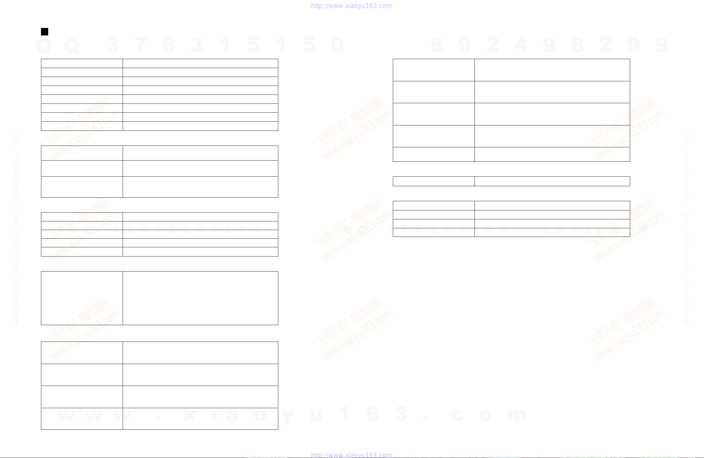
Yamaha MT 400 User manual

SERVICE MANUAL
PA 011437
19981101-45000 1.95K-998 Printed in Japan ’98.10
HAMAMATSU, JAPAN
CONTENTS
SPECIFICATIONS ................................................ 3/4
DIMENSIONS ........................................................... 4
PANEL LAYOUT .................................... 5
CIRCUIT BOARD LAYOUT ................. 8
BLOCK DIAGRAM
............................ 9
DISASSEMBLY PROCEDURE ............................ 10
IC BLOCK DIAGRAM .................................. 11
CIRCUIT BOARDS ...................................... 12
INSPECTIONS ....................................................... 15/17
TROUBLE SHOOTING ............... 19
CIRCUIT DIAGRAM ............................................... 21
PARTS LIST
4
4TR4 STEREO
+6
+3
0
–5
–10
+6
+3
0
–5
–10
POWER
AUX SEND
STEREO INPUT
METER SELECTREC SELECT
MONITOR/PHONES
ZERO STOP
PITCH
NOISE REDUCTION SYSTEM
TAPE SPEED CONTROL
321 RL
REC
REC PLAY REW FF STOP PAUSE
OFF
R
3
OFF
L
2
OFF
R
1
OFF
L
ON
OFF
ON
OFF
SYNC
STEREO
ST+CUE
CUE
MULTITRACK CASSETTE RECORDER
MIC/LINE INPUT
INSERT I/O
INSERT I/O
12
1
2
345L6R8R7L
4.8/ 9.5
–+
LEVEL
STEREO
7
L
–8
R
010
LEVEL
5
L
–6
R
010
LEVEL
MIN MAX
10
9
8
7
6
5
4
3
2
1
0
GAIN
HIGH
10
9
8
7
6
5
4
3
2
1
0
LINE MIC
–12 +12
MID
–12 +12
LOW
–12 +12
AUX
1
010
AUX
2
MIX CUE MIX CUE MIX CUE MIX CUE
010
010
PAN
INPUT-FLIP
TAPE
TAPE
MIC/
LINE
MIC/LINE
to L
LR
1
GAIN
HIGH
10
9
8
7
6
5
4
3
2
1
0
LINE MIC
–12 +12
MID
–12 +12
LOW
–12 +12
AUX
1
010
AUX
2
010
010
PAN
INPUT-FLIP
TAPE
TAPE
MIC/
LINE
MIC/LINE
to R
LR
2
GAIN
HIGH
10
9
8
7
6
5
4
3
2
1
0
LINE MIC
–12 +12
MID
–12 +12
LOW
–12 +12
AUX
1
010
AUX
2
010
010
PAN
INPUT-FLIP
TAPE
TAPE
MIC/
LINE
MIC/LINE
to L
LR
3
GAIN
HIGH
10
9
8
7
6
5
4
3
2
1
0
LINE MIC
–12 +12
MID
–12 +12
LOW
–12 +12
AUX
1
010
AUX
2
010
010
PAN
INPUT-FLIP
TAPE
TAPE
MIC/
LINE
MIC/LINE
to R
LR
4
MULTITRACK CASSETTE RECORDER
w
w
w
.
x
i
a
o
y
u
1
6
3
.
c
o
m
Q
Q
3
7
6
3
1
5
1
5
0
9
9
2
8
9
4
2
9
8
T
E
L
1
3
9
4
2
2
9
6
5
1
3
9
9
2
8
9
4
2
9
8
0
5
1
5
1
3
6
7
3
Q
Q
TEL 13942296513 QQ 376315150 892498299
http://www.xiaoyu163.com

IMPORTANT NOTICE
This manual has been provided for the use of authorized Yamaha Retailers and their service personnel. It has been assumed
that basic service procedures inherent to the industry, and more specifically Yamaha Products, are already known and under-
stood by the users, and have therefore not been restated.
WARNING : Failure to follow appropriate service and safety procedures when servicing this product may result in per-
sonal injury, destruction of expensive components and failure of the product to perform as specified. For
these reasons, we advise all Yamaha product owners that all service required should be performed by an
authorized Yamaha Retailer or the appointed service representative.
IMPORTANT : This presentation or sale of this manual to any individual or firm does not constitute authorization certifi-
cation, recognition of any applicable technical capabilities, or establish a principal-agent relationship of
any form.
The data provided is belived to be accurate and applicable to the unit(s) indicated on the cover. The research engineering, and
service departments of Yamaha are continually striving to improve Yamaha products. Modifications are, therefore, inevitable
and changes in specification are subject to change without notice or obligation to retrofit. Should any discrepancy appear to
exist, please contact the distributor’s Service Division.
WARNING : Static discharges can destroy expensive components. Discharge any static electricity you body may have
accumulated by grounding yourself to the ground buss in the unit (heavy gauge black wires connect to
this buss.)
IMPORTANT : Turn the unit OFF during disassembly and parts replacement. Recheck all work before you apply power
to the unit.
WARNING: CHEMICAL CONTENT NOTICE!
The solder used in the production of this product contains LEAD. In addition, other electrical/electronic and/or plastic (Where
applicable) components may also contain traces of chemicals found by the California Health and Welfare Agency (and possibly
other entities) to cause cancer and/or birth defects or other reproductive harm.
DO NOT PLACE SOLDER, ELECTRICAL/ELECTRONIC OR PLASTIC COMPONENTS IN YOUR MOUTH FOR ANY REASON WHAT
SO EVER!
Avoid prolonged, unprotected contact between solder and your skin! When soldering, do not inhale solder fumes or expose
eyes to solder/flux vapor!
If you come in contact with solder or components located inside the enclosure of this product, wash your hands before handling
food.
WARNING
Components having special characteristics are marked and must be replaced with parts having specification equal to those
originally installed.
MT400
2
w
w
w
.
x
i
a
o
y
u
1
6
3
.
c
o
m
Q
Q
3
7
6
3
1
5
1
5
0
9
9
2
8
9
4
2
9
8
T
E
L
1
3
9
4
2
2
9
6
5
1
3
9
9
2
8
9
4
2
9
8
0
5
1
5
1
3
6
7
3
Q
Q
TEL 13942296513 QQ 376315150 892498299
http://www.xiaoyu163.com

SPECIFICATIONS
3
MT400
DC 12V (650 mA or higher)
388 x 102 x 354 mm
2.8 kg
AC adapter KPA4N, KPA6N
C46–90 cassette tapes (Type II)
4-track/4-channel, One-way Record-Play
4-track Record-Play, Hard Permalloy x 1, 4-track Erase, Ferrite x1
DC servo motor x1
4.8 cm/s, 9.5 cm/s
Approximately+/–10%
0.12% WRMS (9.5 cm/s)
Approximately 120 seconds for a C60 tape
Mixer
Power Requirement
Dimensions (WxHxD)
Weight
Option for UK model
EQ LOW/Shelving Basic frequency: 80 Hz, Range: ±12 dB
MID/Peaking Basic frequency: 1 kHz, Range: ±12 dB
HIGH/Shelving Basic frequency: 12 kHz, Range: ±12 dB
Tape Type
Track Configuration
Tape Heads
Motor
Tape Speed
Pitch Control
Wow & Flutter
Rewind Time
Recorder
Overall Frequency Response
Overall S/N Ratio
Overall Distortion
Erasure Rate
Noise Reduction
50 Hz–14 kHz, +3/–5 dB (9.5 cm/s, NR OUT)
80 dB/IHF-A (NR IN) [at 3% distortion level]
2.0% (400 Hz, –10 dB)
55 dB (1 kHz, 0 dB, BPF)
dbx TYPE II
Connections
# of I/Os
MIC/LINE x4
INSERT I/O x2
STEREO IN x2
AUX SEND x2
STEREO OUT L, R x1
MONITOR OUT L, R x1
SYNC OUT x1
PHONES L, R x1
I/O Specifications
INSERT OUT CH 1, 2 Output Impedance: 100ohm
Rated Load Impedance: 10 kΩor higher
Rated Output Level: –10 dB (10 kΩload)
PHONES (STEREO) Rated Load Impedance: 8 to 40ohm
Rated Output Level: 30 mW+30 mW (40ohm load)
Control Jack
PUNCH I/O Foot switch: FC5 (optional)
General
0 dB=0.775 Vrms.
Tape Transport
Frequency Response
S/N Ratio (at rated input &
output levels)
20 Hz–20 kHz, +1/–4 dB, MIC IN—STEREO OUT
LINE IN—MONITOR OUT
65 dB/IHF-A, MIC IN—STEREO OUT (GAIN TRIM MAX)
70 dB/IHF-A, LINE IN—STEREO OUT (GAIN TRIM MIN)
MIC/LINE
INSERT IN CH 1, 2
STEREO IN
Input Impedance: 10 k ohm
Rated Input Level: –10 to –50 dB (CH fader at rated levels)
Minimum Input Level: –56 dB (Gain trim max. CH fader max)
Input Impedance: 10 k ohm
Rated Input Level: –10 dB (CH fader at rated levels)
Minimum Input Level: –16 dB (CH fader max)
Input Impedance: 10 k ohm
Rated Input Level: –10 dB (CH fader at rated levels)
Minimum Input Level: –16 dB (Volume max)
STEREO OUT L, R
AUX SEND
MONITOR OUT
SYNC OUT
Output Impedance: 1 k ohm
Rated Load Impedance: 10 k ohm or higher
Rated Output Level: –10 dB (10 k ohm load)
Output Impedance: 1 k ohm
Rated Load Impedance: 10 k ohm or higher
Rated Output Level: –10 dB (10 k ohm load)
Output Impedance: 1 k ohm
Rated Load Impedance: 10 k ohm or higher
Rated Output Level: –10 dB (10 k ohm load)
Output Impedance: 1 k ohm
Rated Load Impedance: 10 k ohm or higher
Rated Output Level: –10 dB (10 k ohm load)
w
w
w
.
x
i
a
o
y
u
1
6
3
.
c
o
m
Q
Q
3
7
6
3
1
5
1
5
0
9
9
2
8
9
4
2
9
8
T
E
L
1
3
9
4
2
2
9
6
5
1
3
9
9
2
8
9
4
2
9
8
0
5
1
5
1
3
6
7
3
Q
Q
TEL 13942296513 QQ 376315150 892498299
http://www.xiaoyu163.com

MT400
5
LEVEL
7L–8R
010
LEVEL
5L–6R
010
8
MONITOR/PHONES
STEREO
ST+CUE
CUE
STEREO
LEVEL
MIN MAX
10
9
8
7
6
5
4
3
2
1
0
9
10
11
GAIN
HIGH
10
9
8
7
6
5
4
3
2
1
0
LINE MIC
–12 +12
MID
–12 +12
LOW
–12 +12
AUX
1
010
AUX
2
MIX CUE
010
010
PAN
INPUT-FLIP
TAPE
TAPE
MIC/
LINE
MIC/LINE
to L
LR
1
1
2
3
4
5
6
7
MONITOR LEVEL control
MONITOR select switch
STEREO fader
9
10
11
PANEL LAYOUT
Input channels
GAIN control
EQ control
AUX controls
CUE control
INPUT-FLIP switch
PAN control
Fader
1
2
3
4
5
6
7
Stereo Input
LEVEL controls
8
Monitor / Master Section
w
w
w
.
x
i
a
o
y
u
1
6
3
.
c
o
m
Q
Q
3
7
6
3
1
5
1
5
0
9
9
2
8
9
4
2
9
8
T
E
L
1
3
9
4
2
2
9
6
5
1
3
9
9
2
8
9
4
2
9
8
0
5
1
5
1
3
6
7
3
Q
Q
TEL 13942296513 QQ 376315150 892498299
http://www.xiaoyu163.com

MT400
6
12
13
14
15
16
17
18
19
20
PITCH control
Tape speed switch
REC SELECT switches
METER SELECT switch
dbx switch
ZERO STOP switch
Tape counter
Counter reset button
Cassette compartment
Recorder Section
Transport Section
4TR4 STEREO
METER SELECTREC SELECT
ZERO STOP
PITCH
NOISE REDUCTION SYSTEM
TAPE SPEED CONTROL
OFF
R
3
OFF
L
2
OFF
R
1
OFF
L
ON
OFF
ON
OFF
SYNC
4.8/ 9.5
–
+
12 13 14 15
16 17
18
19
20
REC PLAY REW FF STOP PAUSE
21 22 23 24 25 26
button ( )
PLAY button ( )
REW button ( )
FF button ( )
STOP button ( )
PAUSE button ( )
21
22
23
24
25
26
REC
w
w
w
.
x
i
a
o
y
u
1
6
3
.
c
o
m
Q
Q
3
7
6
3
1
5
1
5
0
9
9
2
8
9
4
2
9
8
T
E
L
1
3
9
4
2
2
9
6
5
1
3
9
9
2
8
9
4
2
9
8
0
5
1
5
1
3
6
7
3
Q
Q
TEL 13942296513 QQ 376315150 892498299
http://www.xiaoyu163.com

MT400
7
36
37
38
39
40
POWER ON/OFF switch
DC 12V
SYNC OUT
MONITOR OUTs
STEREO OUTs
30
31
32
33
4
+6
+3
0
–5
–10
+6
+3
0
–5
–10
POWER
321 RL
REC
27
28
29
Meter Section
AUX SEND
STEREO INPUT
MIC/LINE INPUT
INSERT I/O
INSERT I/O
12
1
2
345
L
6
R
8
R
7
L
31 32
30
33
PHONES PUNCH I/O
34 35
SYNC OUT MONITOR OUT STEREO OUT
RLRL
DC 12VPOWER
ON/ OFF
36 37 38 39 40
Input / Output Section
Front Panel
Rear Panel
Level meters
REC SELECT indicator
POWER indicator
27
28
29
MIC/LINE INPUTs 1-4
INSERT I/O
STEREO INPUTs
AUX SEND
34
35
PHONES
PUNCH I/O
w
w
w
.
x
i
a
o
y
u
1
6
3
.
c
o
m
Q
Q
3
7
6
3
1
5
1
5
0
9
9
2
8
9
4
2
9
8
T
E
L
1
3
9
4
2
2
9
6
5
1
3
9
9
2
8
9
4
2
9
8
0
5
1
5
1
3
6
7
3
Q
Q
TEL 13942296513 QQ 376315150 892498299
http://www.xiaoyu163.com

9
BLOCK DIAGRAM
MT400
IC101
31 IC103
27
IC104
31
IC201
31 IC303
27
IC105
31
IC106
IC107
IC110
IC110
IC111
IC108
IC109
21 67
21 67
21 67
21 67
21
31
67
67
MT400-3000 0
w
w
w
.
x
i
a
o
y
u
1
6
3
.
c
o
m
Q
Q
3
7
6
3
1
5
1
5
0
9
9
2
8
9
4
2
9
8
T
E
L
1
3
9
4
2
2
9
6
5
1
3
9
9
2
8
9
4
2
9
8
0
5
1
5
1
3
6
7
3
Q
Q
TEL 13942296513 QQ 376315150 892498299
http://www.xiaoyu163.com

10
DISASSEMBLY PROCEDURE
Fig.1
MT400
[320]: Bind Head Tapping Screw-P 3X10 MFZN2BL (EP630660)
[320]
[320]
1. Lower Case
1-1 Remove the seven (7) screws marked [320]. The
lower case can then be removed. (Fig.1)
4. SUB 2/3, 3/3 Circuit Boards
4-1 Remove the lower case. (See Procedure 1.)
4-2 Remove the three (3) screws marked [320d] and
the two (2) screws marked [320e].
The SUB2/3 circuit board can then be removed.
(Fig.2, Fig.3)
4-3 Remove the four (4) screws marked [320f]. The SUB
3/3 circuit board can then be removed. (Fig.2)
2. Cassette Mechanism
2-1 Remove the lower case. (See Procedure 1.)
2-2 Remove the five (5) screws marked [320a]. The
cassette mechanism can then be removed. (Fig. 2)
3. REC 1/2, 2/2 Circuit Boards
3-1 Remove the lower case. (See Procedure 1.)
3-2 Remove the cassette mechanism. (See Procedure 2.)
3-3 Remove the six (6) screws marked [320b]. The REC
1/2 circuit board can then be removed. (Fig.2)
3-4 Remove the two (2) screws marked [320c]. The REC
2/2 circuit board can then be removed. (Fig.2)
[320e]
[320f] [320b] [320a] [320c]
[320b]
[320c]
[320a]
[320b]
[320b]
[320b]
[320f]
[320d]
REC 1/2
SUB
2/3
SUB
3/3
Fig.2
Fig.3
〈REAR〉
〈FRONT〉
〈REAR〉 〈FRONT〉
〈Bottom〉
〈Top〉
w
w
w
.
x
i
a
o
y
u
1
6
3
.
c
o
m
Q
Q
3
7
6
3
1
5
1
5
0
9
9
2
8
9
4
2
9
8
T
E
L
1
3
9
4
2
2
9
6
5
1
3
9
9
2
8
9
4
2
9
8
0
5
1
5
1
3
6
7
3
Q
Q
TEL 13942296513 QQ 376315150 892498299
http://www.xiaoyu163.com

11
Fig.4
MT400
11A
2
3
4
5
6
7
1Y
2A
2Y
3A
3Y
VSS 8
9
10
11
12
13
14 VDD
6A
6Y
5A
5Y
4A
4Y
TC4069UBP
(
IG001720
)
Hex Inverter
1Input (Output)1
2
3
4
5
6
7
Output (Input)1
Output (Input)2
Input (Output)2
Control2
Control3
VSS 8
9
10
11
12
13
14 VDD
Control1
Control4
Input (Output)4
Output (Input)4
Output (Input)3
Input (Output)3
TC4066BP
(
IX631591
)
Quad Bilateral Swich
BA7755A
(
XH519A00
)
Head Switcher
BA6137
(
XA534A00
)
LED Driver
AN6292NK
(
XJ637A00
)
Dual dbx NR
NJM2068LD
(
XM356A00
)
NJM4558L
(I
X614610
)
M5216L
(
XB419A00
)
M5218AL
(
XH471A00
)
Dual Operational Amplifier
1
A
2345678
IN V
+IN
OUT
AAA +VIN
+IN OUT
BBB
+
B
+
12345
VCC SW GND CTRL1CTRL2
D1
+ + + + +
+
Constant
Current
Circuit
1
D2
2
D3
3
D4
4
GND
5
D5
6
Amp
Output
7
IN
8
VCC
9
389
20
21
26
ENPHASIS
BAND PASS FILTER IN
REC OUT
1
28
GND +
2
27
R/P IN R/P IN
ENPHASIS
4
LINE OUT LINE OUT
5
24
ENPHASIS ENPHASIS
6
23
CCA-A OUT CCA-A OUT
7
22
CCA-B IN CCA-B IN
BAND PASS FILTER IN
REC OUT
10
19
BAND PASS FILTER OUT BAND PASS FILTER OUT
11 13
1618
LEVEL SENSOR IN
TIMING CURRENT ADJ.
LEVEL SENSOR IN
12
17
TIMING CAP. TIMING CAP.
DECODE / ENCODE SW
14
15
SW
B CH.
A CH.
+
DE
OFF
LINE AMP.
OFF
EN ENDE
+
+
+
DE
OFF
BUFFER
EN
EN
OFF OFF
DE DEEN
+
EN
CCA-B
CCA-A
REC OUT
AMP.
OFF
LEVEL SENSOR
OFF
DE DEEN
+
+
EN PHASIS
AMP.
25
IC BLOCK DIAGRAM
5. SUB 1/3 Circuit Board
5-1 Remove the lower case. (See Procedure 1.)
5-2 Remove the PITCH knob of the TAPE SPEED
CONTROL on the upper case and the six (6) screws
marked [320g].
The SUB 1/3 circuit board can then be removed.
(Fig.4)
6. MIX 1/3 Circuit Board
6-1 Remove the lower case. (See Procedure 1.)
6-2 Remove the SUB 1/3 circuit board. (See Procedure 5.)
6-3 Remove the knob on the upper case and the twelve
(12) screws marked [320h].
The MIX 1/3 circuit board can then be removed.
(Fig.4)
7. MIX 2/3, 3/3 Circuit Boards
7-1 Remove the lower case. (See Procedure 1.)
7-2 Remove the four (4) screws marked [320I] on the
plate. The plate with the MIX 2/3 and 3/3circuit
boards can then be removed. (Fig.4)
7-3 Remove the holding plate of each jack. The each
circuit board can then be removed.
[320h]
[320h]
MIX 1/3
[320i]
MIX 2/3
[320h]
[320g]
SUB 1/3
[320g]
MIX 3/3
[320i]
〈FRONT〉〈REAR〉
w
w
w
.
x
i
a
o
y
u
1
6
3
.
c
o
m
Q
Q
3
7
6
3
1
5
1
5
0
9
9
2
8
9
4
2
9
8
T
E
L
1
3
9
4
2
2
9
6
5
1
3
9
9
2
8
9
4
2
9
8
0
5
1
5
1
3
6
7
3
Q
Q
TEL 13942296513 QQ 376315150 892498299
http://www.xiaoyu163.com

12
MT400
to REC 1/2-CN504
to SUB 1/3-CN101
to MIX 3/3-CN110
to MIX 2/3-CN109
to SUB 2/3-CN107
to MIX 2/3-CN112
to MIX 2/3-CN108
to SUB 1/3-
CN102
CIRCUIT BOARDS
MIX-1/3 Circuit Board
Component side MIX : MT400-3400
w
w
w
.
x
i
a
o
y
u
1
6
3
.
c
o
m
Q
Q
3
7
6
3
1
5
1
5
0
9
9
2
8
9
4
2
9
8
T
E
L
1
3
9
4
2
2
9
6
5
1
3
9
9
2
8
9
4
2
9
8
0
5
1
5
1
3
6
7
3
Q
Q
TEL 13942296513 QQ 376315150 892498299
http://www.xiaoyu163.com

from MIX 1/3-CN101
1-INSERT I/O MIC / LINE INPUT
2-INSERT I/O
from MIX 1/3-CN111 to MIX 1/3-CN109
1 2 3 4 5L 6R 7L 8R
STEREO INPUT
from MIX 1/3-CN103
12
AUX SEND
SYNC
OUT
from MIX 1/3-CN104
from REC 1/2-CN507
LR
STEREO OUT
LR
MONITOR OUT
to REC 1/2-CN506
DC IN POWER SW.
to REC 1/2-CN501
to REC 1/2
-CN502
from MIX 1/3
-CN106
from MIX 1/3-CN107
13
MT400
MIX-2/3 Circuit Board
Component side
MIX-3/3 Circuit Board
Component side
SUB-1/3 Circuit Board
Component side
SUB-2/3 Circuit Board
Component side
SUB-3/3 Circuit Board
Component side
MIX : MT400-3400
SUB : MT400-3600
w
w
w
.
x
i
a
o
y
u
1
6
3
.
c
o
m
Q
Q
3
7
6
3
1
5
1
5
0
9
9
2
8
9
4
2
9
8
T
E
L
1
3
9
4
2
2
9
6
5
1
3
9
9
2
8
9
4
2
9
8
0
5
1
5
1
3
6
7
3
Q
Q
TEL 13942296513 QQ 376315150 892498299
http://www.xiaoyu163.com

14
from REC 1/2-CN503
PUNCH I/O PHONES
to REC 2/2-CN508
from SUB 1/3-CN104
from SUB 3/3-CN109from SUB 1/3-CN103to SUB 2/3-CN108
from MIX 1/3-CN105
MT400
REC-1/2 Circuit Board
Component side
REC-2/2 Circuit Board
Component side
REC : MT400-3500
w
w
w
.
x
i
a
o
y
u
1
6
3
.
c
o
m
Q
Q
3
7
6
3
1
5
1
5
0
9
9
2
8
9
4
2
9
8
T
E
L
1
3
9
4
2
2
9
6
5
1
3
9
9
2
8
9
4
2
9
8
0
5
1
5
1
3
6
7
3
Q
Q
TEL 13942296513 QQ 376315150 892498299
http://www.xiaoyu163.com

MT400
15
INSPECTIONS
A. Preparation
1. Set Up
Set the level controls and switches as follows (unless otherwise specified).
1-1 CH 1, 2, 3, 4
GAIN VOLUME LINE
EQ/ HIGH, MID, LOW VOLUME CENTER
AUX 1, 2 VOLUME MINIMUM
CUE VOLUME MINIMUM
INPUT FLP SWITCH MIC/ LINE
PAN VOLUME CENTER
CH FADER MINIMUM
1-2 CH 5/6, 7/8
LEVEL VOLUME MINIMUM
1-3 MASTER
MASTER FADER MINIMUM
MONITOR LEVEL VOLUME MINIMUM
MONITOR SELECT SWITCH STEREO
1-4 RECORDER
REC SELECT SWITCH OFF
dBx SWITCH OFF
1-5 MECHANISM
PITCH CONTROL VOLUME CENTER
TAPE SPEED SWITCH 9.5 cm/sec
ZERO STOP SWITCH OFF
1-6 OTHER
METER SWITCH 4TR
2. Input /Output
The handled signal level is assumed to be 0 dB = 0.775 V.
The input levels should be sine wave 1 kHz and -10 dBm, unless otherwise specified. Each output terminal should have the following
load resistance.
STEREO OUT 10 kohm
MONITOR OUT 10 kohm
AUX OUT 10 kohm
SYNC OUT 10 kohm
PHONES (STEREO) 40 ohm
3. Position of CH / MASTER FADER
When the input levels for each channel are as specified, the CH FADER is positioned so that the ST/OUT (L/R) is at -10 dBm and the
pointer is between 7 and 8.
4. Tapes
Alignment tape TDK: AC514 (VU167300)
MAXELL: UD II U60
Test tape A.BEX: TCC-121(TX911840) 315 Hz, -4 dB, 160 nWb / m
A.BEX: TCC-151(TX800460) 6.3 kHz
A.BEX: TCC111(TX911820) 3 kHz, -10 dB
A.BEX: TCW211(TX911550) 1.5 kHz, -4 dB
w
w
w
.
x
i
a
o
y
u
1
6
3
.
c
o
m
Q
Q
3
7
6
3
1
5
1
5
0
9
9
2
8
9
4
2
9
8
T
E
L
1
3
9
4
2
2
9
6
5
1
3
9
9
2
8
9
4
2
9
8
0
5
1
5
1
3
6
7
3
Q
Q
TEL 13942296513 QQ 376315150 892498299
http://www.xiaoyu163.com

MT400
16
5. Test equipment required
Low Frequency Oscillator
AC voltmeter (level meter)
DC voltmeter
Oscilloscope
Frequency Counter
Mirror Cassette SONY: MC112C (TX911100)
Torque meter SONY: TW-2231 (TX913450), etc.
6. Mechanical adjustment
6-1 Tape running
Check that a tape curl is not created when playing the mirror tape.
When a tape curl occurs, adjust the height of the head after attaching a Y washer.
6-2 Torque check
Check that the torque of each measurement is within the standard listed below by using a torque meter.
Measurement Mode Standard
FF torque FF 55 120 gcm
REW torque REW 55 120 gcm
PLAY torque PLAY 30 60 gcm
BT torque PLAY 1 6 gcm
Adjustments Test
Tape Test
Equipment Mode Condition Test
Point Adjusting
Point Standard
1dBx
voltage -- DC
Voltmeter -- -- TP101
TP201
TP301
TP401
VR103
VR203
VR303
VR403
18.4 +/- 0.2 mV
+ -
2 Tape speed TCW-211
TCC-111 Frequency
counter PLAY 9.5 cm check should
have the priority MONIT-
OR OUT VR501(9.5 cm)
VR502(4.8 cm) 3000 +10 / -0 Hz
3Azimuth
and phase TCC-151 AC
Voltmeter
Oscilloscope
PLAY INPUT-FILP: TAPE
FADER-3,4: MAX
PAN-3: L, PAN-4: R
MONIT-
OR OUT Azimuth
adjusting
screw
Output: maximum
Phase: in-phase
4 Playback
level TCC-121
TCC-151
AC
Voltmeter
Oscilloscope
PLAY TAPE SPEED: 9.5 cm TP601-1P
TP601-2P
TP601-3P
TP601-4P
TP601-1P
TP601-2P
TP601-3P
TP601-4P
VR101
VR201
VR301
VR401
VR102
VR202
VR302
VR402
285 +/- 10 mV
135 mV (-15 +/- 3 dBm)
5Bias
frequency -- Frequency
counter REC /
PAUSE TP501 L501 80 +/- 1 k Hz
6Bias
oscillation
waveform
-- Oscilloscope REC /
PAUSE TP102
TP202
TP302
TP402
L104
L204
L304
L404
Position the waveform recess at
the center.
+ -
7 Recording
Bias Alignment
tape AC
Voltmeter
Oscilloscope
REC TAPE SPEED: 9.5 cm
Input frequency: 1 k Hz
14 k Hz
Output level: -30 dBm
CH1
CH2
CH3
CH4
VR105
VR205
VR305
VR405
Adjust the output level of 14
kHz to the same level as the
output level of 1 k Hz.
8 Recording
level Alignment
tape AC
Voltmeter
Oscilloscope
REC
PLAY TAPE SPEED: 9.5 cm
Input frequency: 1 k Hz
Output level: 285 mV
Record and play in the
condition above.
CH1
CH2
CH3
CH4
VR104
VR204
VR304
VR404
285 +/- 10 mV
7. Electrical adjustments
w
w
w
.
x
i
a
o
y
u
1
6
3
.
c
o
m
Q
Q
3
7
6
3
1
5
1
5
0
9
9
2
8
9
4
2
9
8
T
E
L
1
3
9
4
2
2
9
6
5
1
3
9
9
2
8
9
4
2
9
8
0
5
1
5
1
3
6
7
3
Q
Q
TEL 13942296513 QQ 376315150 892498299
http://www.xiaoyu163.com

MT400
19
TROUBLESHOOTING
Symptom Advice
MT400 cannot be turned on.
Make sure the AC adapter is connected to a suitable AC wall outlet
securely and plugged into the DC 12V connector at the rear of the
MT400.
Make sure that a correct AC adapter is being used.
Make sure that the MT400 POWER switch is set to the ON position.
Cannot listen to a connected music
source.
Make sure that the [INPUT-FLIP] switches and the monitor select
switch are set to the appropriate positions. When an [INPUT-FLIP]
switch is set to "MIC/LINE ( )", raise the corresponding input
channel fader and the STEREO fader, and set the monitor select
switch to "STEREO" or "ST+CUE". When an [INPUT-FLIP] switch is
set to "TAPE ( )", raise the corresponding channel CUE control
and the STEREO fader, and set the monitor select switch to "STE-
REO" or "ST+CUE".
Cannot push in the button. Make sure that tape's write-protect tabs are intact.
REC
Cannot record.
Make sure that the [REC SELECT] switch is not set to "OFF".
Make sure that you have assigned the signal that you want to record
to the track. Use the CUE control to see if the signal is actually being
sent to the track.
The level meters do not indicate sig-
nal levels.
Make sure that the [METER SELECT] switch is set correctly.
Make sure that the recording track is in recording pause mode.
Recordings are noisy. Use the dbx noise reduction.
Make sure that the recording level is set correctly. Too low a signal
level will cause the tape hiss to be more noticeable.
Recordings are distorted. Make sure that the recording level is set correctly. Too high a signal
level will cause distortion.
Recordings sound dull.
Abnormal tape hiss.
Wow and flutter.
Fluctuating output level.
Clean the record-play head and other parts of the tape transport.
Demagnetize the record-play head.
Recordings play back at a lower (or
higher) pitch by one octave. Use the same tape speed as for recording.
Cannot send a channel signal to the
AUX SEND.
In addition to turning up the AUX control, you must also raise the
channel fader. This is because the AUX SEND signal is source post-
fader (i.e., after the fader).
MIDI sequencer does not synchronize
to the MT400.
Make sure that the FSK/MIDI or SMPTE/MIDI converter is set to con-
vert the recorded SYNC signal into MIDI Clock or MTC.
Make sure that your MIDI sequencer is set to synchronize to an
external MIDI Clock or MTC. Refer to the MIDI sequencer's user
manual.
w
w
w
.
x
i
a
o
y
u
1
6
3
.
c
o
m
Q
Q
3
7
6
3
1
5
1
5
0
9
9
2
8
9
4
2
9
8
T
E
L
1
3
9
4
2
2
9
6
5
1
3
9
9
2
8
9
4
2
9
8
0
5
1
5
1
3
6
7
3
Q
Q
TEL 13942296513 QQ 376315150 892498299
http://www.xiaoyu163.com
Other manuals for MT 400
1
Table of contents
Other Yamaha Cassette Player manuals

Yamaha
Yamaha K-220 User manual

Yamaha
Yamaha MT120S User manual

Yamaha
Yamaha MT100 User manual

Yamaha
Yamaha KX-300 User manual

Yamaha
Yamaha K-220 User manual

Yamaha
Yamaha TC800GL User manual

Yamaha
Yamaha KX-W302 User manual

Yamaha
Yamaha DTR2 User manual

Yamaha
Yamaha MT120 User manual

Yamaha
Yamaha TC800GL User manual