K-ro2()
' Usespacer
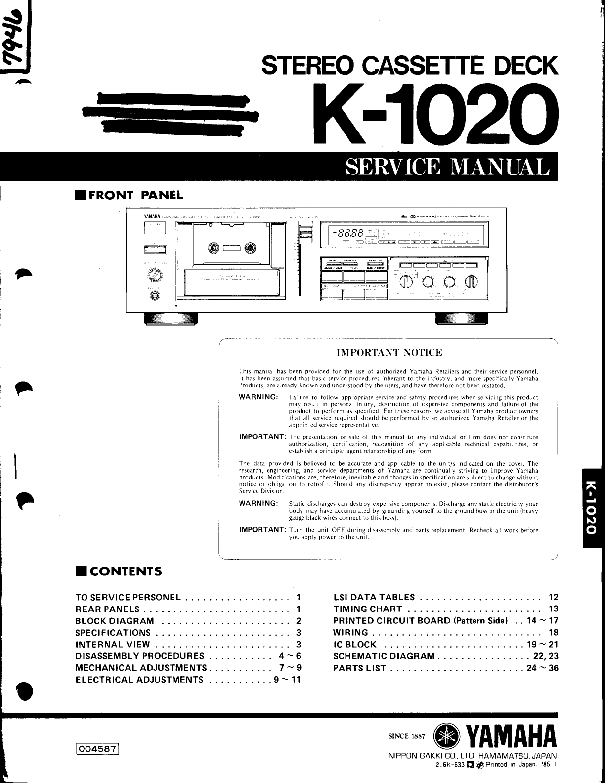
to adjust the h8sd heighl Fig. HFig.I
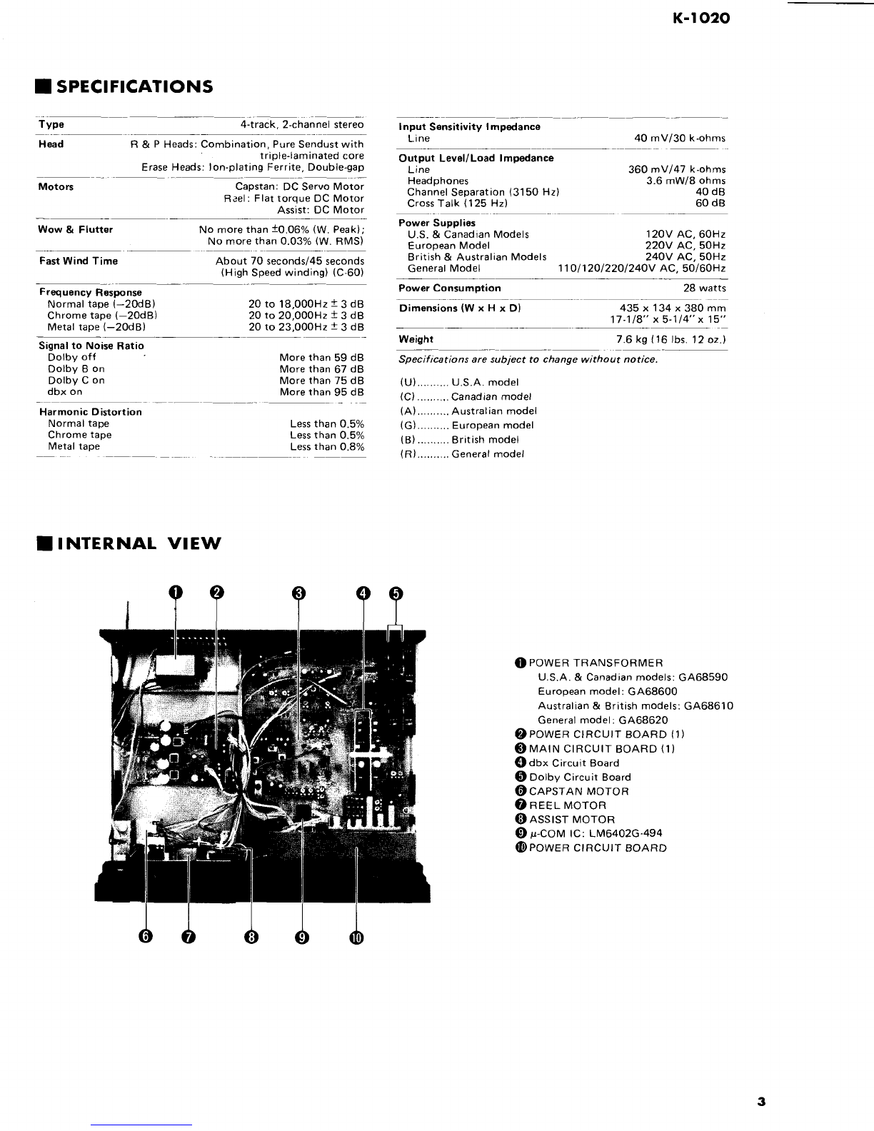
Capslsn Moto.
Fig.J
I ELECTRI
CAL ADJUSTMENTS
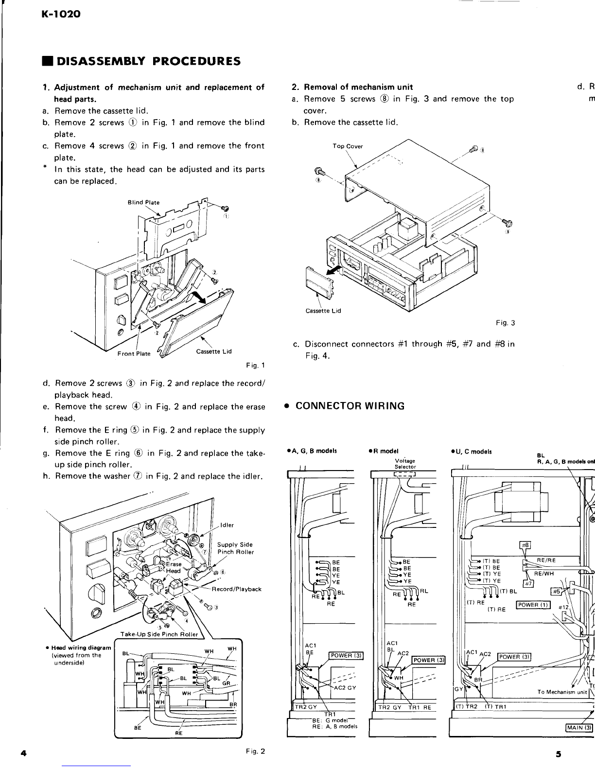
O PLAYBACK
ADJUSTMENTS
* Makesureto use
a new tape of I
ECstandards
for atest
taDe.
Alignmenttape
Normal TDK AC223 or YAMAHA NR 60
CrO2 TDK AC512 or YAMAHA CR 60
METAL TDK ACl12 or YAMAHA MR 60
o Proceed
with the playback
adjustmentsafter having
finished
the mechanical
adjustments.
] (dbx
circuit I I
{dbx
circuit i
I 1 board) 1-____1 I board) I
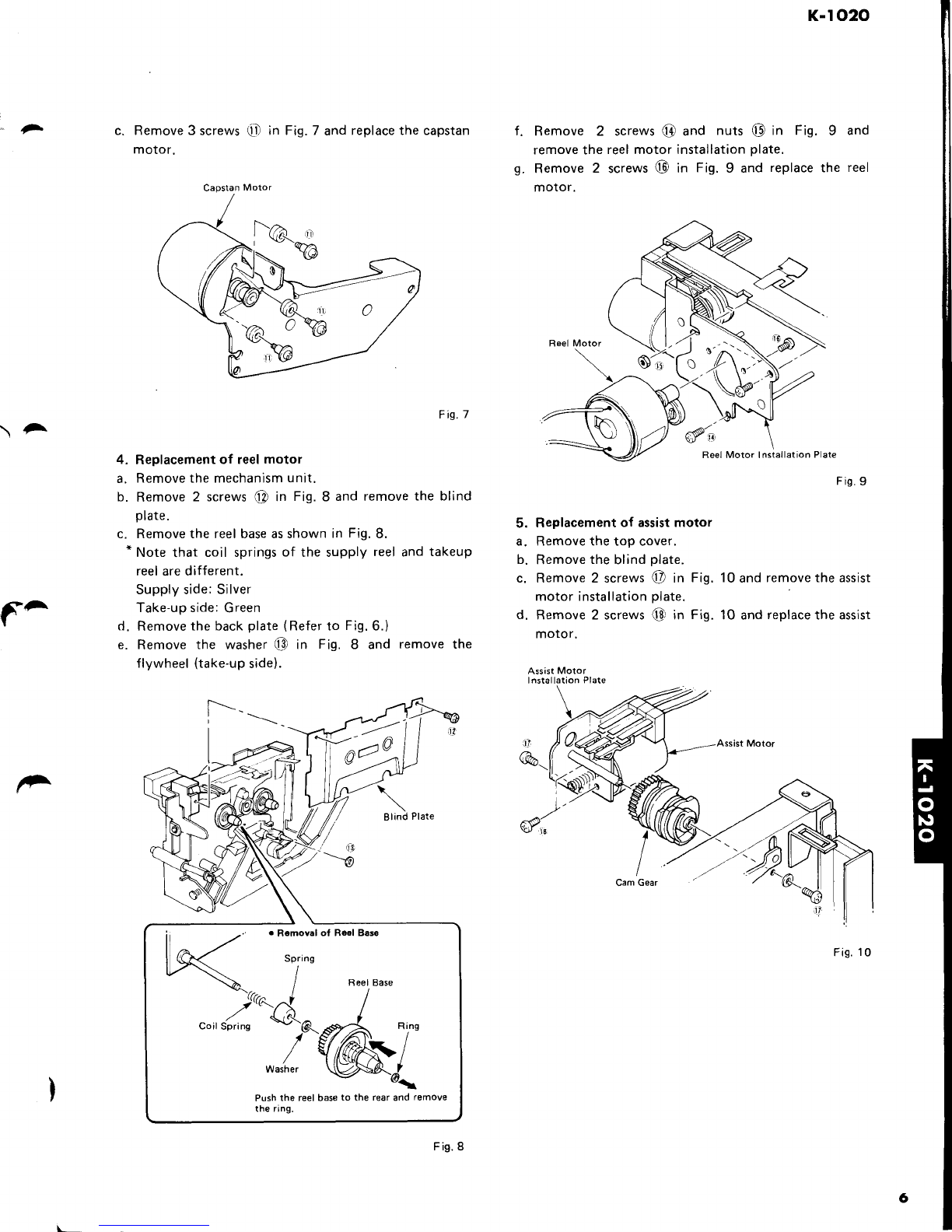
. RECORDINGADJUSTMENT
. Proceedwith the recording
adiustments
after havingfinished
the playback
adjustments.
{
t
uHe8d
Hei0hr
Orivcr
/
/
(]-\
\\\ \\ \
F;f *r;,-.";;-l-;""- -j-,*l1;l*-[ Tffr# JW";;11
E.o^-" r J;';iat-r-I D.cr/M
frtorl *roir'il- o.rfoc --
i iDc.offset lrP2{B)-E i I I vR102(R) i
i-t-lFr"yb".ki'^
r - i{tztzc l Lrrveou-f-eivnr---trl uRlon-L)
-i 36otls--v
--
I I | 1stsa, \ i (Acvort/da I I vR1o4(R) I t-g.o+tdBv)
i I I \toonwo/m/ I I rvteter)
I l
F_+ _+ _ __ f__t _ I
I s ietayuacr
rrequency Mrr.3s6u I r-rr.re
oui I ; 6nt i t-f---T;"*;,"*;'"
J i r".oonre
confirmation I {3t80
+70ps1 i 1 1 lshoutd
bewrthin
specifi-
response
conTtrmatton (J tUU
+ /Ups, 1 i lshould
bewtthin speciti-
I ],.I,.r';',,tuo|,,I I i ] lcationinFie'K
a ldbx rc 1 Tpl -rp2 D.C.V.M. 1
Srop 1 vRTOt i 15
t 2mVD.C.
I I (dbx
circuit ] {dbx
circuit
t-Aai-'tf"ntT , " -"t^Tt T..rj:l:jt- ,. . ' M"".u,"-"nt Jnai"tln"',tl *;- *.*,--
["n".n=."";r lL^;F;;* faoa*".AppryarkHz
sine*;-]u"*.tLr-r l*aaE
r"n-*,-i -'-l
Meter OUT signal
from LINE lN so iVR5O4
{R) I
(red}
should I
r 1(+4.5dBl I rLiNE l-Au;it that LINE OUT voltasers I ltisf't. I
r ltno
uott j li-,i"
]fll$,"."", $'J*,i,'-iyJrlirtase
is
I lrisht i
fF;k L"*f oscillator f,ppty" rri. rinu
*u* fvnsor tr-r I
ooe,"g-"n, -iwrt"n
nllnsrEn
-----l
Meter signal
from LINE lN so 1VR502
(R) i(redl should FADER isdecreasedL l
l(OdB) 1 that LINE OUT voltage i tliStrt. and R segments
i 'is 360mV (-gdBV). L aroundOdBshould
I 1 fade
out almostsimul-
* Use360mV
(-9dBV) for 0dBas
the
standardlevelof
this
unit.
. \')A
9
8ek Teosion (5 iteps)
at Playback mode @
@@
l(OdB) 1 that LINE OUT voltage I llight. and R segments
is
360mV {-gdBV}. ] around
OdBshould
' , I L fade
out almostsimur- i
_l _ taneousty. I