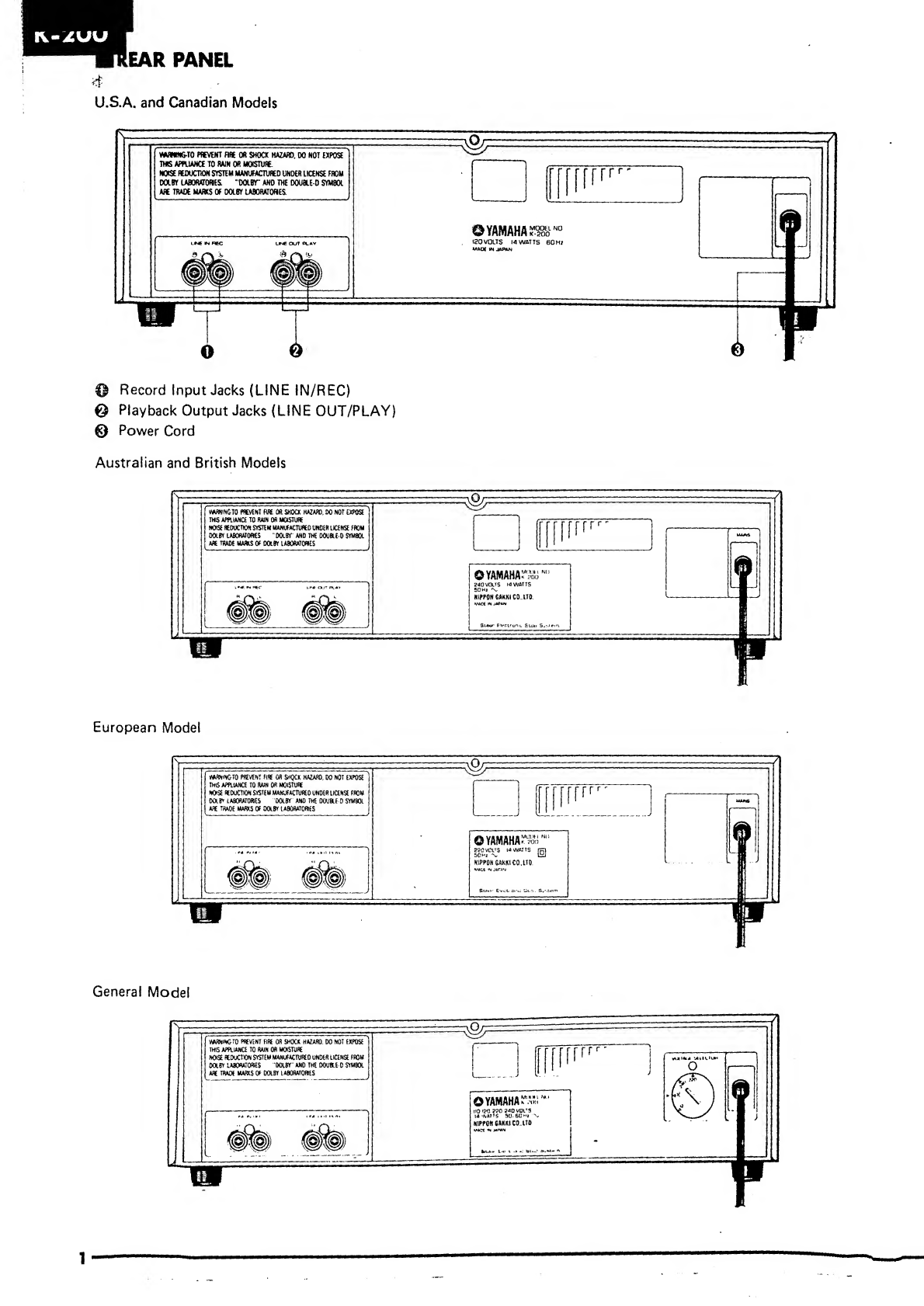
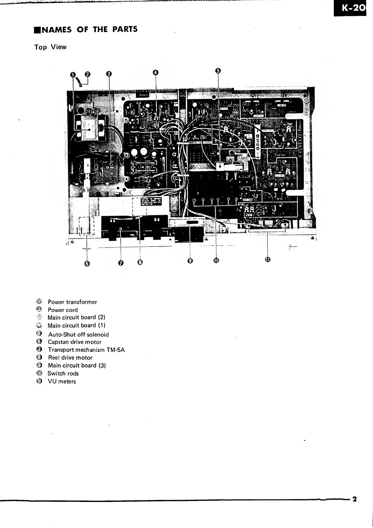
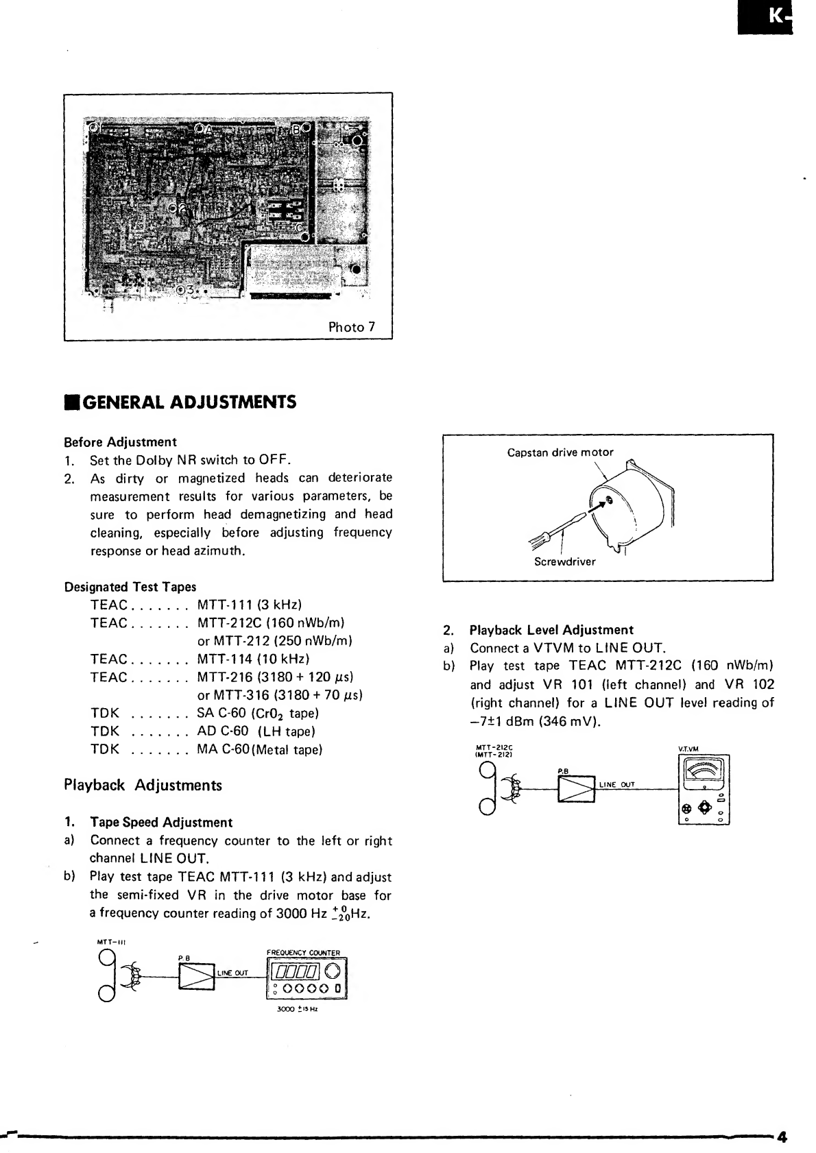
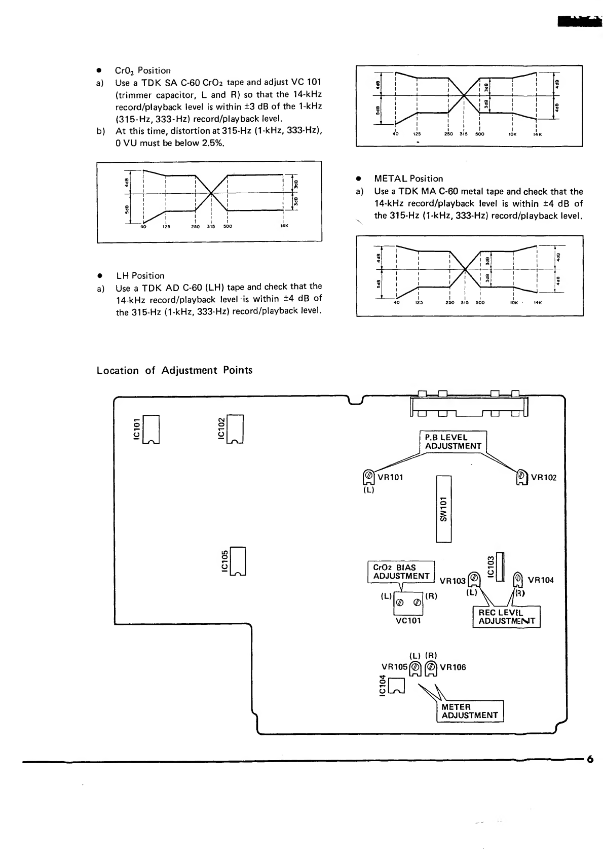
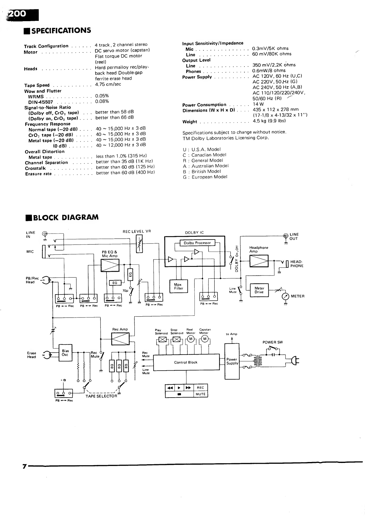
Yamaha K-200 User manual

/*\
STEREO
CASSETTE
DECK
SERVICE
MANUAL
■
FRONT
PANEL
©
Power
Switch
(POWER)
Eject
Button
(EJECT)
©
Cassette
Holder
©
Tape
Counter/Reset
Button
(TAPE
COUNTER/RESET)
©
Rewind
Button
(
«
)
©
Play
Button
(
>
)
©
Fast-Forward
Button
(
W>
)
©
Stop
Button
(
□
)
'?•
Record-Standby/Pause
Button
(R
EC/PAUSE)
Record-Muting
Button
(MUTE)
S
VU
Level
Meters
(LEVEL)
©
Tape
Selector
Switches
(TAPE)
Q
Dolby
NR
Switch
(DOLBY
NR)
■
J
Headphone
Jack
(PHONES)
^
Microphone
Jacks
(MIC)
Record
Level
Control
(REC
LEVEL)
■
C
ONTENTS
Rear
Panel.
Names
of
the
Parts.
Disassembly
Instructions
.
General
Adjustments.
Specifications
....
Block
Diagram
....
..
Performance
Chart
for
Mechanism
Logic...
Printed
Circuit
Board
Pattern-side
Layout.
Printed
Circuit
Board
Parts-side
Components
Layout/Wiring
Schematic
Diagram.
.
.
.
....
1
..
2
.
3
.
4
.
7
..
.
7
...
8
..
.
10
..
.
.
.
11
..
.
.
.
12
SINCE
1887
H
YAMUHA
NIPPON
GAKKI
CO.,
LTD.
HAMAMATSU.
JAPAN
Printed
in
Japan
5.82
erj
<&)
2
.
65K

@
Record
Input
Jacks
(LINE
IN/REC)
©
Playback
Output
Jacks
(LINE
OUT/PLAY)
©
Power
Cord
Australian
and
British
Models
European
Model
General
Model
1

■
N
A
MES
OF
THE
PARTS
Top
View
©
Power
transformer
Power
cord
@
Main
circuit
board
(2)
Q
Main
circuit
board
(1)
©
Auto-Shut
off
solenoid
©
Capstan
drive
motor
©
Transport
mechanism
TM-5A
©
Reel
drive
motor
©
Main
circuit
board
(3)
©
Switch
rods
©
VU
meters
2
Mat,

K-200
■
DISASSEMBLY
INSTRUCTIONS
1.
R
e
m
o
val
of
Top
Cover
Remove
screws
(T)
and
(g)
shown
in
photo
1
(4
screws
each
right
and
left)
and
remove
plastic
rivet
(5)
.
The
top
cover
can
now
be
removed.
2.
R
e
m
o
val
of
Bottom
Cover
Remove
screws
(T)
~
(§)
shown
in
fig
2,
and
remove
the
bottom
cover.
3.
R
e
m
o
val
of
Front
Panel
a)
Remove
the
top
and
bottom
covers
per
steps
1,
and
2.
b)
Remove
screws
(T)
~
(§)
shown
in
photo
3,
and
remove
the
front
panel.
4.
R
e
m
o
val
of
Transport
Mechanism
a)
Remove
the
front
panel
according
to
step
3.
b)
Remove
the
cassette
cover.
c)
Unplug
all
connectors
from
the
mechanism
section.
d)
Remove
screws
(T)
~
(?)
shown
in
photo
4,
and
remove
the
transport
mechanjsm.
5.
Removal
of
VU
Meters
a)
Remove
the
front
panel
according
to
step
3.
b)
Remove
screw
(T)
shown
in
photo
5,
and
remove
the
VU
meters.
6.
Removal
of
Circuit
Board
a)
Remove
the
top
and
bottom
covers
and
the
front
panel
according
to
steps
1,
2
and
3.
b)
Remove
screws
(
5
)
and
(§)
shown
in
photo
5.
c)
Remove
the
plastic
rivets
(A)
and
(§)
shov/n
in
photo
6.
d)
Remove
screw
(T)
shown
in
photo
7,
and
renove
plastic
rivets
(A)
~
(C)
.
e)
After
removing
all
switch
rods,
the
circuit
board
can
be
detached.
3

K
Photo
7
■
GENERAL
ADJUSTMENTS
Before
Adjustment
1.
Set
the
Dolby
NR
switch
to
OFF.
2.
As
dirty
or
magnetized
heads
can
deteriorate
measurement
results
for
various
parameters,
be
sure
to
perform
head
demagnetizing
and
head
cleaning,
especially
before
adjusting
frequency
response
or
head
azimuth.
Designated
Test
Tapes
TEAC.MTT-111
(3
kHz)
TEAC.MTT-212C
(160
nWb/m)
or
MTT-212
(250
nWb/m)
TEAC.MTT-114
(10
kHz)
TEAC.MTT-216
(3180+
120
jus)
or
MTT-316
(3180
+
70
us)
TDK
.SA
C-60
(Cr0
2
tape)
TDK
.ADC-60
(LH
tape)
TDK
.MA
C-60
(Metal
tape)
Playback
Adjustments
1.
Tape
Speed
Adjustment
a)
Connect
a
frequency
counter
to
the
left
or
right
channel
LINE
OUT.
b)
Play
test
tape
TEAC
MTT-111
(3
kHz)
and
adjust
the
semi-fixed
VR
in
the
drive
motor
base
for
a
frequency
counter
reading
of
3000
Hz
-
+
2°oHz.
MTT-HI
c
c
frequency
counter
5
P.B
LINE
OUT
OODO
O
:
OOOO
0
-
-
2.
Playback
Level
Adjustment
a)
Connect
a
VTVM
to
LINE
OUT.
b)
Play
test
tape
TEAC
MTT-212C
(160
nWb/m)
and
adjust
VR
101
(left
channel)
and
VR
102
(right
channel)
for
a
LINE
OUT
level
reading
of
—7±1
dBm
(346
mV).
3000
t
'5
Hz

K-200
3.
Head
Azimuth
Adjustment
a)
Remove
the
cassette
cover.
b)
Connect
two
VTVMs
and
an
oscilloscope
to
the
left
and
right
channels
of
LINE
OUT.
c)
Play
test
tape
TEAC
MTT-114
(10
kHz)
and
turn
the
R/P
head
azimuth
adjustment
screw
so
that
the
outputs
.of
both
left
and
right
channels
are
maximum,
equal,
and
in
phase.
d)
After
adjustment,
apply
screw
lock
paint.
4.
Playback
Frequency
Response
Check
a)
Connect
a
VTVM
to
LINE
OUT.
b)
Play
test
tape
TEAC
MTT-216
(3180
+
120
/is
:
LH)
or
MTT-316
(3180
+
70/ts
:
Cr0
2
)
and
confirm
that
the
10-kHz
reading
is
within
±3
dB
of
the
315-Hz
reading.
MTT-216
(MTT-316)
LINE
OUT
VTVM
Recording
Adjustments
1.
L
e
vel
Meter
Adjustment
a)
Connect
an
audio
oscillator
to
LINE
IN
and
a
VTVM
to
LINE
OUT.
b)
Put
the
deck
into
the
record
mode
and
apply
a
1-kHz
signal
to
LINE
IN
which
will
cause
—7
dBm
(346
mV)
at
the
LINE
OUT.
c)
Adjust
VR
105
(left
channel)
and
VR
106
(right
channel)
so
that
the
VU
meter
pointers
read
0
dB
±1.5
dB.
2.
R
ec
ord
Level
Adjustment
a)
Establish
the
same
connections
as
for
level
meter
adjustment,above.
b)
Put
the
deck
into
the
record
mode
and
apply
a
315-Hz
(1-kHz,
333-Hz)
signal
to
LINE
IN
which
will
read
-7
dBm
(346
mV)
at
LINE
OUT.
c)
Use
the
TDK
SA
C-60
Cr0
2
tape
and
record
this
signal.
d)
Adjust
VR
103
(left
channel)
and
VR
104
(right
channel)
so
that
the
recorded
signal
reads
-7
dBm
(346
mV)
upon
playback.
VTVM
OSClLLArOH
0
©fi
u
o
ooo
oc
p
e
\
UNCOUT
*
e:
-TaBm
t<
3.
C
h
e
ck
of
Recording
Bias
Current
*Set
the
DOLBY
NR
switch
to
OFF.
a)
Connect
an
audio
oscillator
to
LINE
IN
and
a
VTVM
and
distortion
meter
to
LINE
OUT.
b)
Apply
a
signal
to
LINE
IN
which
will
read
—27
dBm
(34.6
mV,
-20
VU)
at
LINE
OUT.
5

•
Cr0
2
Position
a)
Use
a
TDK
SA
C-60
Cr02
tape
and
adjust
VC
101
(trimmer
capacitor,
L
and
R)
so
that
the
14-kHz
record/playback
level
is
within
±3
dB
of
the
1-kHz
(315-Hz,
333-Hz)
record/playback
level.
b)
At
this
time,
distortion
at
315-Hz
(1-kHz,
333-Hz),
0
VU
must
be
below
2.5%.
•
LH
Position
a)
Use
a
TDK
AD
C-60
(LH)
tape
and
check
that
the
14-kHz
record/playback
level
is
within
±4
dB
of
the
315-Hz
(1-kHz,
333-Hz)
record/playback
level.
•
METAL
Position
a)
Use
a
TDK
MA
C-60
metal
tape
and
check
that
the
14-kHz
record/playback
level
is
within
±4
dB
of
the
315-Hz
(1-kHz,
333-Hz)
record/playback
level.
Location
of
Adjustment
Points
P.B
LEVEL
ADJUSTMENT
a
Cr02
BIAS
ADJUSTMENT
(L
«
(
R
)
(®)
VR104
//(«)
REC
LEVEL
ADJUSTMENT
(L)
(R)
!
□
METER
ADJUSTMENT

■
SPECIFICATIONS
Track
Configuration
....
4
track
,
2
channel
stereo
Motor
.
DC
servo
motor
(capstan)
Heads
Flat
torque
DC
motor
(reel)
.
.
Hard
permalloy
rec/play-
Tape
Speed.
back
head
Double-gap
ferrite
erase
head
.
4.75
cm/sec
Wow
and
Flutter
WRMS.
.
.
0.05%
DIN-45507
.
.
.
0.08%
Signal-to-Noise
Ratio
(Dolby
off,
Cr0
2
tape)
.
better
than
58
dB
(Dolby
on,
Cr0
2
tape)
.
better
than
66
dB
Frequency
Response
Normal
tape
(—20
dB)
.
40
~
15,000
Hz
±
3
dB
Cr0
2
tape
(—20
dB)
.
.
40
-
15,000
Hz
±
3dB
Metal
tape
(—20
dB)
40
~
15,000
Hz
±
3dB
(0
dB)
.
.
.
.
40
~
12,000
Hz
±
3dB
Overall
Distortion
Metal
tape.
.
.
less
than
1.0%
(315
Hz)
Channel
Separation
.
.
.
better
than
35
dB
(1
K
Hz)
Crosstalk
.
.
better
than
60
dB
(125
Hz)
Erasure
rate.
better
than
60
dB
(400
Hz)
Input
Sensitivity/Impedance
Mic
.
0
.
3
mV/5K
ohms
Line
.
6
0
mV/80K
ohms
Output
Level
Line
.
350
mV/2.2K
ohms
Phones
.
0
.
6mW/8
ohms
Power
Supply
.
A
C
120V,
60
Hz
(U,C)
AC
220V,
50
JHz
(G)
AC
240V,
50
Hz
(A,B)
AC
110/1
20/220/240
V,
50/60
Hz
(R)
^
Power
Consumption
......
14
W
Dimensions
(WxHxD)
.
.
.
.
435
x
11
2
x
278
mm
(17-1/8
x
4-13/32
x
11")
Weight
.
4
.
5
kg
(9.9
ibs)
Specifications
subject
to
change
without
notice.
TM
Dolby
Laboratories
Licensing
Corp.
U
:
U.S.A.
Model
C
:
Canadian
Model
R
:
General
Model
A
:
Australian
Model
B
:
British
Model
G
:
European
Model
■
BLOCK
DIAGRAM
7

K-2
IPERFORMANCE
CHART
FOR
MECHANISM
LOGIC
FWD
SW104
2
button
-»push
-
-
►
Cl78
charged
-
►
TRI
13
—
base
of
TR113
-
via
R202
“ON”
locked
by
D127
I
d
i
f
ferenti-
I
ation
at
C176|
1C
105
pin6
“H"
pin7
“L”
REEL
MOTOR
forward
drive
HEAD
plunger
operation
Dill
con¬
ductive
BRAKE
plunger
operation
TRI20I
“ON”
I
CAPSTAN
MOTOR
drive
voltage
to
TR
109,110
Auto
Shut-off
circuit
stand-by
TR
II
5
“OFF”
TRI
07,
108
►
“OFF”
Muting
circuit
released
REC
button-
►
push
SWIOI
SW
101
-
I,
3,
5,7,9
SW
101
-2,
4,6,8,
10
L.
ch;
recording
circuit
established
R.
ch.
recording
circuit
established
^
TRII5
TRI07,
108
SWI0M
1
“OFF”
“OFF”
Muting
circuit
released
REC
INDICATOR
lights
SW
101-12
voltage
to
TR117
Tape
Selector
circuit
operation
Record
Protection
Tab
present
missing
REC
IHN
SW
open
closed
1C
105
pin
14
“L”
“H”
1C
105
pin
15
“H”
“
L
”
voltage
to
TR
116
Recording
Bias
circuit
operation
Shut-off
plunger
"ON"
REC
button
lock
disabled

button
■
*
push
SW104-3
voltage
to
-
TR109.110
Auto
Shut*off
circuit
stand-by
REW
|
button
->
push
SW
104-1
TRI
13
“ON”
base
of
TR113
locked
by
D126
REEL
MOTOR
reverse
drive
voltage
to
-----^
TR109.110
Auto
Shut-off
circuit
stand-by
FF
(REW)I
mode
STOP
button
-PUSH
SW
104-4
|
charge
of
Cl79
released
BRAKE
plunger
operation
POWER
SW
SWI03

6
7
8
9
10
n
,
i
r
—
7T-]

■
S
C
H
E
MATIC
DIAGRAM
RESISTOR
_
CAPACITOR
RE
M
ARKS
I
PARTS
NAME
[REMARKS
I
PAR
7
NO
MARK
CARBON
FILM
RESIS
TOR
NO
MARK
CERAMIC
Cl
_
®
SEMI
VARIABLE
RE
SISTOR
®
POLYESTEL
POLYPROPYL

■
P
R
I
N
T
E
D
CIRCUIT
BOARD
PATTE
I

■
PRINTED
CIRCUIT
BOARD
PARTS-SIDE
COMPONENTS
LAYOUT/WIRir
rt.ciifejr
s
LINE
OUT/PLAY
UNE
IN/REC
MAIN
C.BOARD(I)
RIGHT
REC
INDICATOR
Temporary
circuit
board
To
connector
#5.
To
reel,
capstan
motor
and
rec
ihn
sw.

PARTS
L
K-200
STEREO
CASSETTE
DECK
■
C
O
N
T
ENTS
■
E
XPLODED
VIEW(Allover)
.
■
P
ARTS
LIST
(Allover).
■
E
XPLODED
VIEW
(Mechanism)
■
P
ARTS
LIST
(Mechanism).
■
P
ARTS
LIST
(Circuit
Board)
Main
Circuit
Board
.
Page
••••1
.2
.3
4
.
6
Notes
DESTINATION
ABBREVIATIONS
CANADIAN
EUROPEAN
BRITISH
GENERAL
AUSTRALIAN
JAPAN
NIPPON
GAKKI
CO..
LTD.
HAMAMATSU.
JAPAN
Primed
in
Japan
5.82
2.65K
004463


Ref.
No.
Part
No.
Description
(®
=
D
=
S)
Remarks
Co
mmon
model
Markets
Ref.
No.
Part
No
Description
(«
a,
«)
Remarks
Common
model
Markets
*
1
SM;6o|l8jOO
Cassette
Meahanism
TM-5A(S)
&
26
NB
60
69
60
Bottom
Cover
Unit
tf
FAF
*
n
SM
160:19:00
tt
''
(B)
tt
Black
Model
G
27
CB
60
99
80
Cord
Clamper
ZX—Y
9=7
>'<
—
&
2
NB
;60157
150
Panel
Unit
/<*)\,=L-y
F
28
Ei
03
01
00
Bind
Head
Tapping
Screw
3X1
0(ZMC2-Y)
*'<4>Y9ttK>9*i>
*
"
NB:60:57:60
it
•
Black
Model
G
29
Ei
04
01
40
*
4
X
14(
"
)
"
Power
Transtormor
&
3
NA
;07
|89
joO
Main
Circuit
Board
'>
■
<
>'>—
F
J
30
EN
13
00
10
*
3x6
(
"
)
tt
Type-
II
*
"
NA
:07
:89
10
"
a
U,C
31
EK
63
50
30
B-W
Head
P-tyte
Screw
4Xl2(FCM3-3g)
»B.W
Top
Cover
*
*
NA
|07
;89
i20
*
"
G.B
32
CB
60
92
60
Plastic
Rivet
<(>
3
H-yF
&
•«
NA
|07
:89
:30
"
R,A
33
CB
60
32
40
*
03.5
it
*
»
NA
i07
;89
;40
*
n
Black
Model
G
34
CB
61
04
00
*
"
*
4
GA
:65
|26
:00
Power
Transformer
J
35
EV
20
03
00
Plain
Washer
03(ZMC2-Y)
*
tt
GA
!65
|27
!00
a
a
UC
36
CB
61
03
90
Leg
m
&
it
GA
:65
28:00
n
n
G
*
37
CB
61
22
40
Cushion,
C.Board
'>
—
F
9
y
is
3
>
&
n
GA
!65
30j00
«
It
A,B
&
n
GA
:65:29
iOO
*
It
R
5
LB
120114180
Voltage
Selector
R
6
CB:06:86:30
Cord
Stopper
SR-3P-4
3-KXl*
J,U,C
*
"
CB
;60
|99
-50
//
SR-5N-4
it
R,A,G,B
*
7
Ji
:00
il
2
:50
VU
Meter
(S)
VUX-?-
&
ff
Ji
iOO
ji
2
|60
n
(B)
n
Black
Model
G
8
mg|oo
;04
;i
o
AC
Cord
Black
2.2m
7A/125V
mm
?
-
k
J
*
MG
iOO
|07i80
n
■
2m
6A/250V
R
if
MG:00
08:40
tt
*
*
10A/125V
It
Inter-
U,C
»
MG
iOO
12140
H
//
tt
ft
changeable
u,c
if
MG
00
:09
|20
It
Gray
2.5m
7.5A/250V
tt
A
n
MG
00
j09
|50
«
2m
2.5A/250V
tt
G
it
IMG:00:10|00
it
Black
2m
6A
300/500V
tt
B
&
9
CB
|60
|80190
Rod
Power
P
y
Kv
POWER
&
10
CB
:61
:02:30
Button,
Power
it
CB
j61
|02|40
ft
tf
Black
Model
G
&*
11
CB
:60
:81
iOO
Lid
Cover
y
k*/<-
*
n
CB
;60
|91
;30
a
Black
Model
G
i
s
■
r
*
12
CB
;61
:01
:30
Push
Button
~7
y'>
zltY
9
>
*
tt
CB
|ei
|oi
!40
*
n
Black
Model
G
\
*
13
CB
;61
:01
:50
Operation
Button
A
P-*^tf
A
*
*
CB
|61
joi
:60
«
A
*
A
Black
Model
G
*
14
CB
:61
101
:70
"
B
"
B
*
*
CB
;61
loi
|80
"
B
»
B
Black
Model
G
*
15
CB
:61
:01
:90
*
c
»
C
*
tt
CB
;61
|02|00
•
c
*
c
Black
Model
G
*
16
CB
:60:81
:50
Rod,
REW
#1
P
"j
K,
REW
*
17
CB
j60
;81
i60
"
PLAY
#2
*
PLAY
i
as
18
CB
:60:81
:70
«
FF
#3
//
FF
19
CB
!60
=81
|80
»
STOP
#4
#
STOP
*
20
CB
:60
:81
:90
*
REC
#6
«
REC
X
21
CB
-60
|82
|oO
*
MUTE
#5
*
MUTE
s
22
BA
:08
:24:70
Knob,
Bouble
L
9
-fjis'y-7
i
L
*
■
BA
j08
;29
;10
”
L
*
L
Black
Model
G
t
!
K
23
BA
:08
:24
;80
»
R
»
R
i-
s
n
BA
|08
|29
!20
*
R
»
R
Black
Model
G
&
24
AA
:61
:05
:70
Metal
Fitting
r-x&A
*
25
AA
!61
i06
!
10
Top
Cover
F
"j
*
n
AA
:61
ji
3
:00
tt
n
Black
Model
G
---L
*
:
New
Parts
(*r@fe)
*
:
New
Parts

(
IPARTS
LIST
(Mechanism)
SM
SM
PB
160
ed
iK
06
jis
i-19
21
50
GF
00
01
90
GF
00
01
80
KA
60
05
20
BA
08
18
90
BA
08
28
30
CB
06
88
80
NB
60
_
58
30
_
NB
60
58
20
AA
60
88
80
NB
60
33
50
CB
60
61
50
CB
61
1
1
80
AA
60
66
50
JC
00
07
10
NB
60
58
00
00
O
60
61
60
CB
60
61
70
JF
00
03
30
CB
60
61
80
AA
60
88
90
CB
60
75
90
CB
60
61
90
CB
60
62
10
CB
60
62
00
NB
60
33
70
—
CB
60
62
20
NB
60
79
10
Ei
03
01
00
JC
00
07
20
ED
02
62
00
NB
60
33
90
CB
60
62
30
NB
60
34
00
AA
60
89
10
AA
60
89
20
AA
60
89
30
ED
02
01
20
CB
60
62
40
CB
60
61
00
NB
60
33
40
CB
60
61
10
CB
08
26
10
AA
60
88
70
CB
60
98
80
CB
60
98
90
NB
60
34
30
NX
60
00
60
EJ
02
60
80
Description
Counter
REC/Playback
Head
Erase
Head
Leaf
Switch
Blind
Plate
T
Plastic
Rivet
Housing
Ass'y
n
BT-Spring
BT-Disc
Ass'y
Reel
Cap
Mounting
Plate,
Motor
Screw,
Motor
Capstan
Motor
Brake
Ass’y
Cam
Follower
Play-Triger
Solenoid
Ass'y
Cam
Cam-Spring
Senser.
Lid
Stop-Triger
Washer
Rivet
Flywheel
Ass’y
Main
Belt
Back
Plate
Ass’y
Bind
Head
Tapping
Screw
Reel
Motor
Bind
Head
Screw
Gear
Ass'y
Head
Base
Pinch
Roller
Ass'y
Spring,
Return
”
Head
Base
_
*
RPH
_
Bind
Head
Screw
Counter-Belt
Lever,
Play
Look
Damper
Ass'y
Lever,
Lock
Washer
Spring,
Housing
Guide
R,
Cassette
Guide
L,
Cassette
Rell
Base
Ass'y
Chassis,
Mechanism
TM-5A(S)
TM5A(B)
N3.5
Gray
N3.5
Black
03.5
Black
N3
Gray
N3
Black
(ZMC2)
MMi-6
m
A
£)
>5
—
fW^7
K
y~K
i;-7SW
77<>K7V-FT
F
i>
'/
V
Ass’y
BT-X
'?')>'?
BTt-
f
X
?
Ass’y
i)
'
7'
—+
Ass’y
rbA7
*
a
7
Play-
F
'J
V
U'
7
<f
K
Ass’y
*
A
g
!
7
7
K-fe
>4
STOP-
F
M
T*
>J
X
7
-
f
7
7
*>
*
-
F
7
7
T
^
-f
—
yp
Ass’y
X
T
>^<yu
F
'<7
^
F
Ass’y
V
-yne-7-
4-V
Ass’y
^
7
F^
—
X
t:
□
—
7
—Ass’y
•J
?->XZ?')
^7
V^-xx-/')
>7
RPHX7
f
M
f)0>9
—
'Ob
F
yixT
P
-y
^
L"<
—
¥
>'*—
A
ss’y
□
7
?
—
^t7
FffT
KR
*7^7
F#T
KL
U
—yUn
1
Ass’y
X
#if^Ass’y
2.6x8(ZMC2-Y)
Rema
rks
Common
model
(Black
Model
Jg
Black
Model
Black
Model
PW-2.5-7
3X10
BFS9B
2.6X20(ZMC2-Y)
2x12(ZMC2-Y)
R/P
Head
for
Tape
Counter
*
:
New
Parts

•'"N
■
PARTS
LIST
(Circuit
Board)
Ref
No.
IM
F
s
art
No.
Description
(»
&
«)
Remarks
Commo
model
n
Markets
|
:
'
K
mm
m
||U,
C
■
*
*
f^gt
M
mm
MBfe
%
*
■
i
|
•'
;..
v
.
a
—
4
-
m
1
;iQ,
B
>
i!B/A
07
<89
j4C
Black
Mode
liG;-..
C101
C102
UW
;84
■
71
oc
Electroytic
Capacitor
10/iF
25V
J
tz^>
C103
C104
FM;51
;64
7C
4.7/*F
25V
Za
>
C105
Cl
06
FG;41
:24
7C
Ceramic
Capacitor
470pF
50V{
K)
■
tr
7
u
>
C109
Cl
10
FG:41
;
12
20
Ceramic
Capacitor
22pF
50V(K)
3
>
C1
11
Cl
12
UA;25;41
20
Mylgr
Capacitor
0.012//F
50V(J)
C
1
13
Cl
14
UW;91
;82
20
.
Electrolytic
Capacitor
220//F
6.3V
i
>
C1
15
Cl
16
UW;84;71
00
n
10//F
25V
It
C
1
1
7
Cl
18
UA
;25:36
80
Mylar
Capacitor
0.0068^F
50V(J)
C1
1
9
Cl
20
FG;4i:21
50
Ceramic
Capacitor
1
50pF
50V(K)
-tr
7
3
>
C
121
C1
22
UW;96;54
70
Electrolytic
Capacitor
0.47^F
50V
&
Z
3
>
C
1
23
Cl
24
FG;71;32
70
Mylar
Capacitor
0.0027^F
50V(J)
7-3
>
Cl
25
C1
26
F
G:41
;31
00
Ceramic
Capacitor
0.001
>uF
50V(K)
3
>
C
1
27
C1
28
UA;25|35
60
Mylar
Capacitor
0.0056//F
50V(J)
V-f
u
>
Cl
29
Cl
30
UA:25:34
70
H
0.0047^/F
50V(J)
II
C
1
31
C
1
32
UW
;
‘84:71
00
Electrolytic
Capacitor
10/iF
25V
Sr
Z
3
>
C
1
33
Cl
34
UA:
25:42
70
Mylar
Capacitor
0.027/iF
50V(J)
V>f7“3>
C
1
35
Cl
36
UW!84j71
00
Electrolytic
Capacitor
10juF
25V
+
Z
3>
C
1
37
Cl
38
UA;25;51
00
Mylar
Capacitor
0.1
/jF
50V(J)
C
1
39
Cl
40
FM:42:53
30
Electrolytic
Capacitor
0.33juF
50V
Z3>
1141
C
142
UW:83i82
20
»
220/iF
16V
^i3>
C
143
Cl
44
F
GJ41
1
2
8
20
Ceramic
Capacitor
820pF
50V(K)
3
>
C1
45
Cl
46
UW:86:62
20
Electrolytic
Capacitor
2.2
u
f
50V
Z
3
>
C147
Cl
48
UW:86;61
00
1
juF
50V
H
Cl
49
Cl
50
UA;25;36
80
Mylar
Capacitor
0.0068//F
50V(J)
7^7-3^
C1
51
C1
52
F
Aj
15
>
33
90
n
0.0039juF
50V(J)
n
C1
53
-1
56
UW:84;
71
00
Electrolytic
Capacitor
lO^F
25V
<rZ
3
V
C1
57
C1
58
UW;86j61
00
n
50V
H
Cl
59
Cl
60
UA;25:51
00
Mylar
Capacitor
0.1
50V(J)
7>f7~3>
C
1
6
1
C162
UW|96:63
30
Electrolytic
Capacitor
3.3juF
50V
+
Z
3>
C1
63
Cl
64
UW;
94;
72
-
i-
f
-
20
n
22
U
F
25V
n
C
165
C
1
66
UW|
91j74
70
a
47juF
6.3V
11
C
1
6
7
C1
68
UW:84:71
00
it
10/iF
25V
”
Cl
69
UKj
16j61
00
it
I^F
50V
B.P3>
Cl
70
UW;84:71
00
n
10//F
25V
<rZ
3>
Cl
71
UW|91
;8i
00
"
100*F
6.3V
H
C172
UW:94:81
00
it
100</F
25V
*
C1
73
C1
74
F
Gj
44|
41
00
Ceramic
Capacitor
0.01
50V(2)
t73
>
Cl
75
1
UW:
94:74
-!-1-
70
Electrolytic
Capacitor
47^F
25V
<rZ
□
>
Cl76
I
UW;84;71
00
H
10*F
25V
H
C177
1
FG:44:41
00
Ceramic
Capacitor
0.01/l/F
50V(Z)
3
>
Cl78
l
JW|
91
■
83
30
Electrolytic
Capacitor
330//F
6.3V
<rZu>
C1
79
|
C1
80
1
UW:84:71
00
*
10//F
25V
n
i
i
Cl82
l
JW:84:82
20
Electrolytic
Capacitor
220//F
25V
<rZ^>
Cl83
l
jw;94;
64;
70
n
4.7//F
25V
a
Cl84
F
:
T
:
8
5
:
3
2
:
7
0
Polypropylene
Capacitor
0.0027//F
100V(J)
^yya3>ECQ-P
*
:
New
Parts
(tr0A)
6

Ref.
No.
Part
No.
Description
(lafl
tSp
Remarks
Common
model
Markets
Cl
85
JW;94|64j70
Electrolytic
Capacitor
4.7jt/F
25V
*rZ
3
V
SHI
UA
125:41:00
Mylar
Capacitor
0.01/iF
50V(J)
-
74*7
—
C187
UA;25:42:70
n
0.027^F50V(J)
a
323!
JWi84:82:20
Electrolytic
Capacitor
220//F
25V
UW;86j61
loo
a
I^F
50V
|
it
Cl
90
H
1000/iF
35V
tt
C191
UW:94:92;20
n
2200//F
25V
C192
Fi
:32:41
iOO
Ceramic
Capacitor
O.Ot^F
AC250V(DE)
J
ft
Fi
j33:41
<00
11
O.OI^F
AC400V(DE)
tt
R,
A
tt
Fi
;34:41
iOO
h
0.01/iF
MY(DE)
U,
C
if
F
R
j
16141
j00
MP
Capacitor
0.01/uF
AC250V
MPu>
G,
B
ram
UA
;25
;44:70
Mylar
Capacitor
0.047/iF
50V(K)
-74
7
—
□
>
wm
f
•11:7.1
F
G:41
'34:70
Ceramic
Capacitor
0.0047^F
50V{K)
*t»7
D
>
C197
UW-84:71:00
Electrolytic
Capacitor
10//F
25V
*r
Z
n
>
o
CO
00
UW
:94:74:70
a
47//F
25V
tt
C199
UW
184171100
a
10^F
25V
tt
m
FG:44|5l]00
Ceramic
Capacitor
O.VF
50V(K)
*tr5
□
>
C201
UW:82:81:00
Electrolytic
Capacitor
lOO^F10V
*Zn>
VC101
F
Y
j00:02•
10
Trimmer
Capacitor
1
80pF
b
2
GE
:20:04:i0
MPX
Coil
MPX
□
4
GE
:90;06:10
Trap
Coil
85K
Y*7'V?^4
O'
T105
GE
:90j06|30
OSC
Coil
85K
OSC
n4J^
L
101
L
102
GE
:90j02:60
Coil
1
2mH
L
103
L
104
GE
-90:08:10
tt
27mH
n
:
:
:
R
101
R102
HJ
:35-41
iOO
Carbon
Resistor
10
Q
RD25S
R
103
R
104
HJ
;35173190
a
39KQ
ft
tt
R
105
R
106
HJ
135163190
tt
3.9KQ
h
tt
R
107
R
108
HJ
;35;76|80
11
68KG
a
tt
R
109
R110
HJ
135:51:20
tt
120n
"
tt
R
11
1
R1
12
HJ
;35:81
;50
n
150KQ
*
tt
R
11
3
R
114
HJ
135:61100
tt
1
KS2
"
tt
R
11
5
R116
HJ
;35i82;70
tt
270KQ
*
tt
R11T
R
11
8
HJ
135:68:20
t,
8.2KQ
*
tt
R119
R1
20
HJ
135:55:60
tt
S60Q
"
tt
R121
—
124
HJ
135:71100
it
10KQ
n
it
R
125
R
1
2
6
HJ
135:81
iOO
tt
100KQ
"
tt
R127
R
1
2
8
HJ
135168120
tt
8.2KS2
tt
tt
R129
R130
hj
I35I71
;oo
tt
10KG
*
h
R131
R
132
HJ
135:61100
tt
1KQ
tt
it
R
133
R
1
3
4
HJ
135163:30
n
3.3KQ
a
•
R135
R136
HJ
135:51
180
tt
180Q
n
tt
R137
R
138
HJ
:35:74i70
a
47KQ
"
*
R
139
R140
HJ
135:71100
tt
10KG
tt
tt
R141
R142
H
J
|35
J81
|80
tt
180
KQ
n
h
R143
R144
HJ
135182:70
n
270KQ
tt
R
145
R146
Hj;35l61
joo
tt
1KQ
h
a
R147
-150
HJ:35154:70
tt
470Q
n
*
R151
R152
HJ
135163130
n
3.3KQ
n
tt
R153
R154
H
J
135162120
11
2.2KQ
n
h
.
*
:
New
Parts
ORSHA)
7
Table of contents
Other Yamaha Cassette Player manuals

Yamaha
Yamaha MT120S User manual

Yamaha
Yamaha TC-511S User manual

Yamaha
Yamaha MT4X User manual

Yamaha
Yamaha MT3X User manual

Yamaha
Yamaha MT100II User manual

Yamaha
Yamaha MT8XII User manual

Yamaha
Yamaha KX-W900U User manual

Yamaha
Yamaha KX-W302 User manual

Yamaha
Yamaha MT50 User manual

Yamaha
Yamaha MT1X User manual