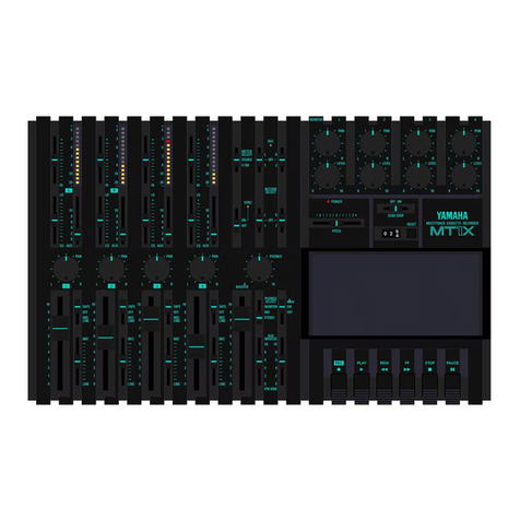
Yamaha MT8X User manual

YAMAHA
AUTHORIZED
PRODUCTMANUAL
MULTITRACKCASSETTERECORDER

YAMAHA
MULTITRACKCASSETTE RECORDER
OPERATION MANUAL

CAUTION:TOREDUCETHERISKOF
ELECTRICSHOCK, DONOTREMOVE
COVER (OR BACK), NO USER-SERVICEABLE
PARTS INSIDE,REFER SERVICING TO
QUALIFIEDSERVICE PERSONNEL.
ExplanationofGraphicalSymbols
Thelightningflashwith arrowheadsymbol,
withinanequilateraltriangle,isintendedto
alertyou tothe presenceofuninsulated
"dangerousvoltage"withintheproduct's
enclosurethatmaybeofsufficient
magnitudetoconstitutea riskofelectric
shocktopersons.
The exclamationpointwithinanequilateral
triangleisintendedto alertyou tothe
presenceofimportantoperatingand
maintenance(servicing)instructionsin
theliteratureaccompanyingthe appliance.
SAFETY INSTRUCTIONS
1ReadInstructions- All thesafety andoperating
instructionsshouldbereadbefore the applianceis
operated.
2RetainInstructions- Thesafety andoperating
instructionsshouldberetainedfor future reference.
3HeedWarnings- All warningsonthe applianceand
intheoperatinginstructionsshouldbeadheredto.
4FollowInstructions- All operatinganduse
instructionsshouldbefollowed.
5Water andMoisture- Theapplianceshouldnotbe
usednearwater - for example,neara bathtub,
washbowl,kitchensink,laundrytub,ina wet
basement,orneara swimmingpool,andthelike.
6CartsandStands- Theapplianceshouldbeused
onlywith a cart or standthatisrecommendedbythe
manufacturer.
6A An applianceandcartcombination
shouldbemovedwithcare.Quick
stops,excessiveforce, anduneven
surfaces maycausetheappliance
andcartcombinationtooverturn.
7Wallor CeilingMounting- Theapplianceshouldbe
mountedtoawallorceilingonlyasrecommended
bythe manufacturer.
8Ventilation- Theapplianceshouldbesituatedso
thatitslocationorpositiondoesnotinterferewithits
properventilation.Forexample,the appliance
shouldnotbesituatedona bed,sofa,rug,or similar
surface, thatmayblocktheventilationopenings;or
placedina built-ininstallation,suchasa bookcase
or cabinetthat mayimpedethe flow ofairthrough
the ventilationopenings.
9Heat- Theapplianceshouldbe situatedawayfrom
heatsourcessuchasHeatregisters,stoves, or
other appliances(includingamplifiers)thatproduce
heat.
10Power Sources- Theapplianceshouldbe
connectedto a powersupplyonlyofthetype
describedintheoperatinginstructionsor as marked
onthe appliance.
11GroundingorPolarization- Theprecautionsthat
shouldbetakensothatthe groundingor
polarizationmeansofanapplianceisnotdefeated.
12Power-Cord Protection- Power-supplycords should
beroutedsothattheyarenotlikelyto bewalkedon
orpinchedbyitemsplaceduponoragainstthem,
payingparticularattentionto cords atplugs,
conveniencereceptacles,andthe pointwherethey
exitfrom theappliance.
13Cleaning- Theapplianceshouldbecleanedonlyas
recommendedbythemanufacturer.
14NonusePeriods- Thepowercord oftheappliance
shouldbeunpluggedfrom theoutletwhen left
unusedfor a longperiodoftime.
15ObjectandLiquidEntry- Care shouldbetaken so
thatobjectsdonotfallandliquidsare notspilledinto
theenclosurethroughopenings.
16DamageRequiringService -Theapplianceshould
beservicedbyqualifiedservicepersonnelwhen:
A. Thepower-supplycord orthe plughasbeen
damaged;
or
B.Objects havefallen,or liquidhasbeen spilledinto
theappliance;or
C.Theappliancehasbeenexposed to rain;or
D.The appliancedoesnotappearto operatenormally
orexhibitsamarkedchangeinperformance;or
E.The appliancehasbeendropped,ortheenclosure
damaged.
17Servicing-Theusershouldnotattemptto service
the appliancebeyondthatdescribedinthe operating
instructions.Ail otherservicing shouldbereferred
toqualifiedservicepersonnel
2

FCCINFORMATION
1. IMPORTANT NOTICE: DONOTMODIFYTHISUNIT!
Thisproduct,wheninstalledasindicatedinthe
instructionscontainedinthismanual,meetsFCC
requirements.Modificationsnotexpressly approvedby
Yamaha mayvoidyour authority,grantedbytheFCC,to
usetheproduct.
2. IMPORTANT : When connectingthisproductto
accessories and/oranotherproductuseonlyhighquality
shieldedcables.Cable/ssuppliedwith thisproduct
MUSTbeused.Followallinstallationinstructions.
Failuretofollow instructionscouldvoidyourFCC
authorizationto usethisproductintheUSA.
3. NOTE: Thisproducthasbeentestedandfound to
comply with therequirementslistedinFCCRegulations,
Part15for Class"B"digitaldevices.Compliancewith
theserequirementsprovidesa reasonablelevelof
assurancethatyour useofthisproductina residential
environmentwillnotresultinharmfulinterferencewith
otherelectronicdevices.
Thisequipmentgenerates/usesradiofrequencies and,if
notinstalledandusedaccordingto theinstructionsfound
in the usersmanual,maycauseinterferenceharmfulto
the operationofotherelectronicdevices.
Compliancewith FCCregulationsdoesnotguaranteethat
interferencewillnotoccur inallinstallations.Ifthisproduct
isfoundtobethesourceofinterference,whichcanbe
determinedbyturningthe unit"OFF"and"ON",pleasetry to
eliminatethe problembyusingoneofthe following
measures:
Relocateeitherthis productorthedevice thatisbeing
affectedbytheinterference.
Utilizepoweroutletsthatareondifferentbranch(circuit
breakerorfuse) circuitsorinstallAC linefilter/s.
In thecaseofradioorTV interference, relocate/reorientthe
antenna.Iftheantennalead-inis300ohmribbonlead,
changethelead-into coaxial type cable.
Ifthesecorrectivemeasuresdonotproducesatisfactory
results,pleasecontactthe localretailerauthorized to
distributethistypeofproduct.Ifyou can notlocatethe
appropriateretailer,pleasecontactYamahaElectronics
Corp.,U.S.A.6660OrangethorpeAve, BuenaPark,CA
90620.
TheabovestatementsapplyONLYtothoseproducts
distributedbyYamaha CorporationofAmerica orits
subsidiaries.
This product complieswiththe radio frequency
interferencerequirementsoftheCouncilDirective
82/499/EEC and/or 87/308/EEC.
CANADA
THISDIGITALAPPARATUS DOESNOTEXCEED THE "CLASS
B" LIMITSFORRADIO NOISEEMISSIONSFROMDIGITAL
APPARATUS SETOUTINTHERADIOINTERFERENCE
REGULATIONOFTHECANADIAN DEPARTMENT OF
COMMUNICATIONS.
IMPORTANTNOTICEFORTHEUNITEDKINGDOM
ConnectingthePlugandCord
IMPORTANT
ConnectingthePlugandCord
IMPORTANT
THEWIRES INTHEMAINSLEADARE COLOURED IN
ACCORDANCE WITHTHEFOLLOWINGCODE:
Blue:NEUTRAL
Brown:LIVE
As the coloursof the wires inthe mainsleadofthis apparatus may
notcorrespondwiththe colouredmarkingsidentifyingthe
terminalsinyour plug,proceed asfollows:
Thewire which iscoloured BLUEmustbeconnected tothe
terminalwhichismarkedwith the letterN orcoloured BLACK.
Thewire which iscoloured BROWNmust beconnected to the
terminalwhich ismarked with the letterL orcoloured RED.
Makingsurethat neithercore isconnected to the earth terminalof
thethreepinplug.
3

CONGRATULATIONS
Your MT8X Multitrack Cassette Recorder is a powerful recording tool that will enable you to work
with sound in many ways. No other multitrack cassette recorder offers the straightforward
simplicity and ease-of-use of the MT8X. Whether you need to record acoustic instruments or voice
using microphones, electronic instruments and line-level sources, or a creative blend of the two,
the MT8X makes the process of building tracks extraordinarily smooth and simple. You can
simply record and remix eight tracks, or use the multitrack "ping-pong" recording technique to
individually record many independent parts adding sound layer by layer until you create
exactly the arrangement and texture your imagination demands with its ability to record on all
eight tracks, or in any combination, MT8X is the ideal choice for recording bands or layering
tracks at home.
And,
because
it’s
a
YAMAHA,
you know
that
the
MT8X
will
give you the very
finest sound quality and overall performance available.
In order to make use of the MT8X’s many features and obtain maximum performance, we urge
you to read this operation manual thoroughly and keep it in a safe place for future reference.
4
PRECAUTIONS...................................................................................5
FEATURES
..........................................................................................6
STRUCTUREOF
THE
MT8X
..............................................................7
CONTROLSAND THEIRFUNCTIONS...............................................8
MIXER(CHANNEL
INPUT
SECTION)
............................................8
MIXER(MASTER
SECTION)..........................................................9
RECORDER
...................................................................................10
DISPLAY........................................................................................12
FRONTPANEL
..............................................................................12
REAR
PANEL
................................................................................13
RECORDINGMETHODS..................................................................14
MONITOR.....................................................................................14
INITIAL
RECORDING
....................................................................15
OVERDUBBING.............................................................................16
PITCHCONTROL
..........................................................................16
PING-PONGRECORDING
............................................................17
PUNCH-IN/OUTRECORDING......................................................20
SYNC RECORDING.....................................................................2
3
MIXDOWN.....................................................................................27
SETTINGTHERECORDINGLEVELS..........................................28
RECORDINGEXAMPLES................................................................29
RECORDING
PLAN.......................................................................29
RECORDINGEXAMPLE1:
Abasicrecording(overdubbing)............................................31
RECORDING EXAMPLE 2:
An
advanced
recording
............................................................35
CONNECTION
EXAMPLE
.................................................................40
TROUBLESHOOTING
.......................................................................41
MAINTENANCE............................................................................42
SPECIFICATIONS............................................................................43
GENERAL
SPECIFICATIONS......................................................4
3
DIMENSIONS.................................................................................44
BLOCK
DIAGRAM.......................................................................12
9
CONTENTS

PRECAUTIONS
1.
AVOID
EXCESSIVE HEAT,HUMIDITY,DUST
AND VIBRATION
Keep the unitaway from locationswhere itislikely
to beexposed tohightemperatures or humidity—
such as nearradiators,stoves, etc.Also avoid
locations which are subject to excessive dust
accumulation orvibration which couldcause
mechanical damage.
2. AVOID PHYSICAL SHOCKS
Strong physical shocks to the unitcancause
damage. Handleitwith care.
3. DONOTOPEN THECASE OR ATTEMPT
REPAIRS OR MODIFICATIONYOURSELF
Thisproductcontainsnouser-serviceable parts.
Forother than routinecleaning,refer maintenance
to qualified YAMAHA personnel.Openingthe case
and/or tampering with the internalcircuitrywillvoid
the warranty.
4. MAKE SURE POWER ISOFFBEFORE MAKING
OR REMOVING CONNECTIONS
Always turn the power OFFpriorto connectingor
disconnecting cables.Thisisimportanttoprevent
damage to the unititselfaswell asother connected
equipment.
5. HANDLE CABLES CAREFULLY
Always plugandunplugcables — includingthe AC
cord — bygripping the connector, notthe cord.
6. CLEAN WITH A SOFTDRY CLOTH
Neverusesolvents such asbenzineorthinnerto
cleanthe unit.Wipe cleanwith a soft, drycloth.
7. ALWAYS USETHECORRECT POWER SUPPLY
This unitissoldwith the appropriatepower
specifications for the localarea (power supply
voltage andpower consumption arelistedon the
bottom panel).Ifyou move to a different areathat
mighthavea different AC mainsvoltage, however,
be sure to check with your nearestYAMAHA dealer
before usingthisunit.
8. KEEP THE HEADS AND TAPE PATHCLEAN
To ensure consistent highperformance andsound
quality from thisunit,itisimportanttoclean the
headand tape pathregularly(ideallybefore each
recording session). Todothis,usea cleaning kit
specifically designed for usewith cassette tape
equipment.
9. USEONLY HIGH-QUALITY CHROME CASSETTE
TAPE
This unitisdesigned to beusedonlywith
Chromeposition tape, and will notwork properly
withFerrichrome tape formulations. tape
10.USEA CASSETTE TAPE PROPERLY
positiontape.CRO2tape(HIGHposition,TYPEII)
shouldbeused.With some tapes, itmaybe
impossibletoobtainnormalsoundqualityor
characteristics becauseof problemssuch as
distortion ofthe frequency characteristic. Ifthis
happens,try usinga different type of tape. TDK SA
46 - 90andMaxellUDII46- 90are
recommended.
Thisunitisan8-track,8-channeltape recorderwith
atape speed of9.5cm/s, unlikeordinarycassette
recorders which have4 tracks, 2 channels,anda
tapespeed of4.8cm/s,sothisunitcannotrecord
or playbackordinarycassette tapes.
Also, sincethisunitusesspecialheads,itisnot
compatible with tapes recordedon 8-track
recordersfrom othermanufacturers.
Newtapes aretightlywound, sofast forward and
rewindthem oncetoloosenthem up.This
improves the recording/playbackcharacteristics.
Also, itisbetter notto usethe first and last20
seconds ofthe tape.Sometimes thesesections
are wound insucha way thatthe desired
characteristicsarenotobtained.
When loadinga cassettetape, checkitcarefully to
makesure the tape isnotloose, thenloadthe tape
firmly intothe cassette compartment so that itis
notlooseor otherwise outofplace.
If the tapeisnotloadedproperly,thedesired
characteristicsmay notbeobtained.
11.USETHEdbx SWITCH PROPERLY
To playbacka tape with normalsound quality,turn
the dbx switch onfor the tape recorded withthe
dbx on,and for the tape recorded with the dbxoff,
turn thisswitch off.
dbx isa trademark ofdbx Incorporated.
12.CHECK THEACCESSORIES
Please checkto see thatyou haveallthe
accessories, power cords andcotton swabs.
Thisunitisdesignedtobeusedonlywith Chrome
(Bias: HIGH; EQ:
7
0
s) shouldbeused.Also, the
5
use of tapes longer than 90minutes (C-120, etc.) is
notrecommended because they exhibit poorer
performance, andcan cause anequipmentfailure.
FEATURES
GENERAL
TheMT8Xconsistsofan8-channelrecordingmixersectionandan8-trackrecordersectioninsideacompact
enclosure.Independentrecordingandplaybackarepossiblefor eachseparatetrack,so thathigh-qualitymulti-track
recordingcanbeeasilyobtained.
MIXER
Themixersectionisequippedwith independentstereobusesfor moreflexibleuseofthisunit.
Continuouslyvariablegaincontrolsareprovidedfor channels1-4.
Theseareapplicabletoanyinputsource,includingmicrophoneinputandlineinput.
InsertI/Ojacksareprovidedforchannels1 and2.Thesejacks allowexternalsignalprocessorstobeconnected
directlytothisunit.
DualAUXSENDandAUX RETURN(stereo)jacksaddeffectsfrom theconnectedexternalsignalprocessorsto
eachchannelasrequired.
2TRINjacksareprovidedto makemonitoringofthe completedtapewhichhasbeenmixed downinstereo easier.
RECORDER
Adbxnoisereductionsystemwillprovidesubstantialnoisereductionanda widedynamicrange.
An automaticpunch-in/outrecordingfunctionanda rehearsalfunctionmakepunch-in/outrecordingeasierandmore
accurate.
Apitchcontrolfunctionmakesitpossibleto vary thetape speedwithina rangeofapproximately±12%. Thisis
usefulincasessuchascarryingoutpitchcompensationatoverdubbing.
Alargemulti-functionaldisplayshowstherecordingandplaybacklevel,recordingtrackandtape countertogether,
soitiseasyto see andvery helpfulfor operations.
AfullcomplementoflocatefunctionssuchasRTZ(ReturnToZero)andLOC(Locate)areprovided.
Afull-logicmechanismintherecordermakestheprocessofcreatingcomplexmulti-trackrecordingsmooth and
simple.
6

STRUCTURE OFTHEMT8X
Thisunitcanbedividedintothree sections:a "mixer",a "recorder"and"buslines"whichlinktheprevioustwo sections.
MIXER:
Thecurrentofinputsignalsateach channel
The mixer has8 inputchannels.Itadjustsinputsignalsateach
respective channelandsendsthem tothe buslines.
The signalsinputtoeachchannelofthe mixercanbeswitched to
eitherinputsignals(LINE)ortape playbacksignals(TAPE).
WhenTAPE isselected, the playbacksignalsoneachtrackare
inputto the correspondingchannel,insucha way thattheplayback
signalsontrack1 ofthe recorderareinputtochannel1,the
playbacksignalsontrack2 ofthe recorderareinputto channel2,
andsoon.Afterthe toneandvolumeoftheinputsignalsare
adjustedattheequalizerandchannelfaders,theyaresentto the
desiredbuslinesusingthe PAN controlsandASSIGN switches.
There are 4 mainbuslines(groupbuses)whichreceivetheinput
signalsfrom eachrespectivechannelofthemixer.
Ifsignalsfrom two ormoremixerchannelsare inputto a busline,
these signalsarealloverlaid(mixing).
RECORDER:
Thecassette recorderrecordsthe signalsfrom thebuslines.In
addition,italsosendsthe playbacksignalsto the TAPE OUTjacks
onthe rear panelandtothemixer.
Forrecording, there isa relationshipbetweengroupbusesand
recordertracks asshowninthefollowingtable.
BUS
LINES:
Trackonwhich signalsfrom thegroupbuscanberecorded
GroupBusNo.
GROUP
1
GROUP2
GROUP3
GROUP4
As shown inthetableonthe left,thereare
asmanyas4 tracks whichcanberecorded
atthe same time.
Inaddition,signalsfrom odd-numbered
groups(ODD)arerecordedtoodd-
numberedtracks,andsignalsfrom even-
numberedgroups(EVEN)arerecorded to
even-numberedtracks.
Track1 orTrack5
Track2 orTrack6
Track3 orTrack7
Track4 orTrack8
Thecurrentofsignalsfrom a channelto therecorder
7

CONTROLS AND THEIRFUNCTIONS
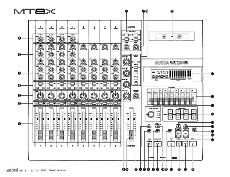
The headnumberofeachcontrolnamecorrespondstothe samenumberoftheillustrationatthe backofthe
attachedPLANNINGSHEET.
MIXER (CHANNELINPUTSECTION)
GAIN ControlandCLIPIndicator
Thiscontroladjusts the levelofsignalsfrom the
microphoneorinstrumentsconnectedto the
MIC/LINEINPUTjacks.
Ifthe CLIPindicatorabove each ofthe knobs(1-4)
remainsilluminated,itmeans thattheinputlevelis
too high.Inthiscase,adjustto anoptimumlevelso
thatthe indicatorflickers momentarilyatthe
maximum volumelevelbyusingtheGAIN controlor
theoutputleveloftheconnectedunit.(GAIN controls
areprovidedonlyfor channels1-4).
EqualizerControls
Thehigh,middleandlowbandfrequency levelscan
becontrolledindividuallywithina rangeof±12dB
basedfromthestandardfrequenciesgivenbelow.
HIGH:Standardfrequency .........10kHz
MID:Standardfrequency ......... 1kHz
LOW:Standardfrequency .........100Hz
When thecontrolisatthe"0"position,a flat
frequencycharacteristicisobtained.(However,
channels5-8areprovidedwithHIGHandLOW
controlsonly.)
Theequalizer'sfrequency characteristics
ASSIGNSwitches
Theseswitchesareusedto sendthe signalswhich
areadjustedbythePANcontroltotherespective
groupbuses.
TheseswitchesandthePANcontrolcanbeusedto
distributesignalsfreely between groups1-4. Onthe
otherhand,signalsarealwayssentto thestereo
buses.
PAN Control
Thiscontrol isusedforadjustingbalanceand
positionofsignalswhichwas adjustedbythe
channelfader,when the signalsaresentto the
groupbusesorstereobuses.
Signalsaredistributedasfollows:
ODD/L:Signalsaresentto Groups1 and/or3 Stereo L).
EVEN/R:SignalsaresenttoGroups2 and/or4 StereoR).
Ifthe controlissetto the center position,signalswill
beequallydistributedto boththe ODD/Land
EVEN/Rgroupsorchannels.
InputSelectorSwitch
Thisswitchisusedto selectthe inputsignal(either
TAPE orMIC/LINE)for eachchannel.
Thisswitchcanalsobeusedto turneachchannel
ON/OFFwhenmixingdownrecordedsources.
TAPE:
Setto thispositioninorderto inputanalready-
recordedsignaltothe mixer.
MIC/LINE(ch1-4), LINE(ch5-8):
Setto thispositionwhen addinganinputsignal
from aninstrumentsuchasanelectricguitarora
keyboardwhich isconnectedtotheMIC/LINE
(LINE)INPUTjacks ontherearpanel.
Amicrophonemayalsobeconnectedfor
channels1-4.
ChannelFader
Thechannelfader isused to adjustthe levelofthe
inputsignals.
Whenmixingchannels,inputlevelbalancebetween
channelscanbeadjustedwiththesefaders.
The optimumpositionisat7-8onthe scale.
AUX1 and2Controls
TheAUX controlsareusedto adjustthe levelof
signalsinputto a unitsuch asanexternalsignal
processorconnectedtotheAUX SENDjack(s).
Thesignalsadjusted bythesecontrolsaresentfrom
theAUXbuslinetothe connectedsignal
processor(s) viatheAUX SENDjack(s). Thesignals
thenreturntothisunit'sgroupbusesandstereo
buses viathe AUX RETURN jacks.
Setthefaderto"0"for channelswhich arenot
beingused.
8

MIXER (MASTER SECTION)
GROUPMASTERControls
Thesecontrolsareusedtoadjustthe levelofeach
groupwhen the signalsfrom eachgroupbusareto
berecordedto tape.Thesignalsadjustedbythese
controlsaresentto the tracks selectedbythe REC
SELECTswitches.
STEREOFader
TheMASTERfaderadjuststhelevelofthe stereo
bussignals.
Theoptimumpositionisat"7-8"onthe scale.
MONITOR/PHONESControl
Thiscontrolisusedto adjustthe soundoutputlevel
atthePHONESjack onthe frontpanelandatthe
MONITOROUTjacks ontherearpanel.
MONITORSELECTSwitches
Theseswitchesareusedto monitorthe groupbus
andstereobussignals,signalsinputto the2TRIN
jacks andthe playbacksignalsofthecassette tape.
Ifallswitchesarepressed,allofthe signalscanbe
simultaneouslymonitored.
GROUP
Eachoftheseswitchesisusedto monitorthebus
signalsfor groups1 and3 or groups2 and4 in
monaural.
Ifboththeswitchesarepressed,signalscanbe
monitoredinstereo;groups1 and3 forchannelL
andgroups2 and4 for channelR.
STEREO
Thisswitchisusedto monitorthe stereo bus
signals.
2TR
IN
Thisswitchisusedto monitorthe signalsinputto
the2TRINjacks.
CUE
Thisswitchisusedto monitortheplayback
signalsontracks ofthecassettetape.
Fora trackbeingrecorded,the recordingsignals
willbemonitored.
AUX RTNLEVELControls
Thesecontrolsareusedtoadjustthe levelofthe
signalsinputto theAUX RETURNjacks.
AUX RTNASSIGNSwitches
Theseswitchesareusedto selectthe groupbusto
whichthesignalsfrom theAUX RETURNjacks will
besent.Ontheotherhand,signalsarealwayssent
tothestereo buses.
9

RECORDER
dbxSwitch
Thisswitchisusedto turn the internaldbxnoise
reductionsystemonandoff.
Thedbxsystemwilloperatewhen the switchis
turned on.Thedbxsystem becomes onatthe time
whenthepower isturned on.
Thedbxsystem hasnoeffectontrack 8 when the
SYNCswitchison.Thisisbecausetrack 8 isused
for recordingthe FSKsignalonSYNC recording.
SYNCSwitch
Whenperforming SYNC recordingorplaybackwith
the dbxon,turn thisswitch on,andrecordFSK
signalsontrack8.(See"SYNCRECORDING"on
page23.)
REHE ButtonandIndicator
Thisbuttonisfor carryingouta recordingrehearsal.
Ifthisbuttonispressed,the indicatorilluminates.
Afterthetrack(s)toberecordedisselected with the
REC SELECTswitches,ifthisbuttonispressed and
thenthePLAY buttonispressed,apseudo-recording
canbeperformed. Inthiscondition,thisunit
functionsinthesame way asactualrecording,
thoughrecordingisnotperformed. Thisisusefulfor
practicingpunch-in/outrecordingand for checking
recordinglevels.
CLEARButton
Thisbuttonclearsthesettingofmemorypoints1 and2.
When automaticpunch-in/outisactivate(AUTO
PUNCHI/Oindicatorilluminates)thisbuttonclears
the automaticpunch-in/outsettingbutdoes notclear
thememory pointsetting.
10

REC/PAUSE ButtonandIndicator
Thisbuttonisusedtoactuallyrecord signalsontoa
cassette tape.Ifthisbuttonispressedafter selecting
atrackto berecordedbyusinga RECSELECT
switch,the indicatorwillilluminateandthisunitenters
intothe recordingstandbymode.Ifthe PLAY button
is thenpressed,recordingwillbegin.
If notrack to berecorded hasalreadybeen
designatedbyusingtheRECSELECTswitches,the
indicatorwillflash rapidlywhen thisbuttonis
pressed.
AUTO PUNCHI/OButtonandIndicator
Thisbuttoncancelstheautomaticpunch-in/out
function. (See"4.Punch-in/outusingtheautomatic
punch-in/outfunction"onpage21.)
CHECKButton
Thisbuttondisplaysthememory point.
If the MEMO1 buttonispressedwhileholdingdown
the CHECKbutton,MEMO[1]willflashonthe
displayandthe tape countervaluewillbeshownon
the display.Ifthe MEMO2 buttonispressed while
holdingdowntheCHECKbutton,the tapecounter
valuefor MEMO2 willbeshown onthedisplay.
PLAY ButtonandIndicator
Thisbutton isusedforplayingthecassette tape.
REWButton
Thisbuttonisusedto rapidlyrewindthecassette
tape.
If thisbuttonispressed andhelddownfor morethan
onesecond,the tapewillberewoundathigher
speed.
FF Button
Thisbuttonisusedto rapidlywind forward the
cassettetape.
Ifthisbuttonispressed andhelddownfor more than
onesecond,thetape willbewound forward athigher
speed.
STOPButton
Thisbuttonstopsthetape running.
MEMO1 and2 Buttons
These buttonsmemorizethe current tapecounter
valueasmemorypoints.
Ifthe MEMO1 buttonispressed,memory point1 is
stored and"MEMO1"isshownonthe display.
Ifthe MEMO2 buttonispressed,memory point2 is
stored and"MEMO2"isshown onthe display.
Thestored memorypointscanbeerasedbypressing
the CLEAR button,byturningoffthe mainpower
supplyorbyremovingthe cassettetape.
LOC1 andLOC2 Buttons
These buttonsarefor locatingthe memory points
storedusingthe MEMO 1 andMEMO2 buttons.
Ifthe LOC1 buttonispressed,the tape rapidly
forwardsorrewindstothe memorypoint1,andwhen
LOC2 ispressed,thetape rapidlyforwards or
rewindsto the memorypoint2.
COUNTERRESETButton
Thisbuttonresetsthetapecounterto "00:00".The
memorypointsonthetapewhich were setbyusing
theMEMO 1and2buttonswillremainunchanged,
evenifvaluesofthetapecounterarechangedby
pressingthisbutton.
RTZ Button
Ifthe RTZ (Return ToZero)buttonispressed,the
tape israpidlyrewound to the pointwhere the
counterreads"00:00".
REPEATButton
Pressingthisbuttonrepeatedlyplaysbackthe
sectionbetweenthetwo memorypointswhichwere
setusingthe MEMO1 andMEMO2 buttons.
If eitheroneofthe memory pointshasnotbeenset,
the sectionbetween 00:00andthe singlememory
pointwillbeplayedbackrepeatedly.
If thisbuttonispressedoncemore,the repeat
playbackiscanceled.Therepeatplaybackwillbe
continuedupto 16times unlessthisfunction is
canceled.
REC SELECTSwitches
Theseswitchesareusedto selectthetracks (1 - 8)
on whichthe groupsignalssent to therecorderareto
be recorded.
Therelationshipofa groupbusandthe tracks on
whichsignalsfrom thegroupbuscanberecorded
areasfollows.
Track1 or5
Track2 or6
Track3 or7
Track4 or8
Group
1
Group2
Group3
Group4
Signalscannotbesimultaneouslyrecorded to two
differenttracks inthe same group,for instancetracks
1and5.Simultaneousrecordingisthuspossiblefor
up tofourtracks.
If the switchispressedonceagain,the settingis
canceled.
PITCHControl
(Knob,
Switch andIndicators)
Thiscontrol isusedto adjustthe runningspeed of
thetape.(See"PITCHcontrol"onpage16.)
If the switch ispressedto enterintotheFIXmode
(thegreenindicatorilluminates),thetape speedis
set to the presetconditionandcannotbechanged.
CUELEVELControls
Thesecontrolsareusedto adjustthemonitoring
levelofthe recording/playbacksignals.Adjustment
canbedonefor eachtrackrespectively.
Cassette Compartment
11

DISPLAY
dbxIndicator
Thisindicatorilluminateswhenthedbxsystemison.
SYNCIndicator
ThisindicatorilluminateswhentheSYNC switchis
pressed to beturnedon.
AutomaticPunch-in/outIndicator
Thisindicatordisplaystheautomaticpunch-in/out
recordingstatus.
MEMO1 and2 Indicators
Theseindicatorsilluminatewhen therespective
memorypointshavebeenset.
If
the
MEM0
1
buttonispressed,
[1]
flashes
three
timesandthenilluminates.
IftheMEMO2 buttonispressed,[2]flashesthree
timesandthenilluminates.
REPEATIndicator
Thisindicatorilluminateswhiletherepeatplaybackis
beingperformed.
TAPE Indicator
Thisindicatorilluminateswhena cassettetapeis
inserted.Ifa cassettetapehasnotyetbeen
inserted,theindicatorwillflashifa buttonfor tape
runningispressed.
RECSelectIndicators
Theindicatorcorrespondingto thetrackselectedby
aRECSELECTswitchflashesto indicatethat
recordingispossibleto thetrack.IftheREC/PAUSE
buttonispressedatthistime,theindicatorchanges
from flashingto illuminatingandthisunitentersinto
therecordingstandbymode.
LevelMeter
Thelevelmeterdisplaystherecordingorplayback
levelofeachtrack,orthesignallevelatthestereo
buseswithina rangeof-20dB- +9dB.
TapeCounter
Thetapecounterisdisplayedbyminutesand
seconds.Thetime displayedisascloseaspossible
to theactualtimeelapsed,buttherewillbea small
amountoferrordependingonthetype oftapebeing
used.Therangeoferrors areasfollows:
C-46:
±13%
(±1
min.30sec.)
C-60:
±10%
(±1
min.30sec.)
C-90: ±13% (±3min.)
FRONTPANEL
PHONESJack
Connectheadphones(8-40)to thisjack.
PUNCHI/OJack
Whenusinga footswitch (soldseparately)inpunch-
in/outrecording,connectthefootswitch to thisjack.
(See"PUNCH-IN/OUTRECORDING"onpage20.)
REMOTECONTROLJack
WhenusingremotecontrollerRCM1 (sold
separately)to operatetherecorder,connectthe
Aview from over
the toppanel.
remotecontrollerto thisjack.
12

REAR PANEL
MIC/LINEINPUT,LINEINPUTandINSERTI/O
Jacks
InputImpedance:10k ,10k,10k
RatedInputLevel:-10dBto -50dB,-10dB,-10dB
MIC/LINEINPUTjacks areprovidedfor channels
1-4,andonlyLINEINPUTjacks areprovidedfor
channels5-8.(Forchannel8 only,stereo inputjacks
areprovided.)Inaddition,INSERTI/Ojacks are
providedforchannels1 and2.
The InsertI/Ocableasshown inthefollowingfigure
is requiredwhen usingINSERTI/O.
AUXSEND1 and2Jacks
OutputImpedance:1 k
Rated OutputLevel:
-10dB(at10k load)
These jacks outputsignalsto beinputto external
signalprocessors.
POWER Switch
Thisswitch turnsthe powersupplyto thisunitonand
off.
Always make surethatthe STEREOfader issetto
"0"andtheMONITOR/PHONEScontrolissetto
"MIN"when turningthisunitonoroff.
MONITOROUTJacks
OutputImpedance:1k
Rated OutputLevel:-10dB(at10k load)
Thesamesignalwhich isoutputfrom the PHONES
jack isalsooutputfrom thesejacks. Theycanbe
usedforconnecting a speakerwith built-inamplifier,
etc.
AC INSocket
Connectthesuppliedpowercord here.
STEREOOUTJacks
OutputImpedance:1 k
RatedOutputLevel:-10dB(at10k load)
Formixdown,connectthesejackstothe stereotape
deck.
AUXRETURN 1 and2Jacks
InputImpedance:20k
RatedInputLevel:-10dB(AUXRTNLEVELcontrolnominal)
Thesejacksinputsignalsfrom external signal
processors.Thesejacksarestereojacks,sothata
stereo signalprocessorwithoneinputandtwo
outputscanbeconnected.Ifusinga signal
processorwith monauraloutputonly,connectto the
L(MONO)sideofthesejacks.
Ifnotusingasignalprocessor, thesejackscan be
usedasstereo inputjacks.
2TRINJacks
InputImpedance:10k
RatedInputLevel:-10dB(MONITOR/PHONEScontrolnominal)
Thesignalscanbemonitoredbyway ofthisunitif
the LINEOUTjacks ofthetape deckareconnected
tothesejacks andthe MONITORSELECTswitchis
setto 2TRIN.
TAPEOUTJacks (1-8/SYNC)
OutputImpedance:100
RatedOutputLevel:-10dB(at10k load)
Thesoundsfor eachtrackareoutputfrom these
jacks directly.Duringplayback,thesoundsfrom the
tracks beingplayedbackareoutput,andduring
recording,thesoundsfromthetracksbeingrecorded
areoutput.Adjustmentofoutputlevelsfromthese
jacks isnotpossible,soadjustthe volume onthe unit
which isconnectedtothe respectivejacks. When
performingSYNCrecording,theSYNCsignalis
outputfromtheTAPEOUT8/SYNCjack.
CAUTION(FORCANADA MODEL)
TO PREVENTELECTRICSHOCK, MATCHWIDEBLADEOF
PLUGTOWIDESLOT,FULLYINSERT.
13

RECORDINGMETHODS
Thefollowingmethodsaresomeofthebasicfunctionsonhowto perform multi-trackrecording.
MONITOR:Monitoringthestatusofrecordingorplayback
INITIALRECORDING:Recordingthefirst sound(part)
OVERDUBBING: A methodfor recordinga newtrackwhile monitoringpreviouslyrecorded
tracks.
PING-PONGRECORDING:A methodfor recordingmixedsignalsofseveralrecordedtracks onto
anothertrack.
PUNCH-IN/OUTRECORDING:A techniqueto re-recorda shortsegmentofanotherwiseperfecttrackin
orderto correcta mistakeor"brushup"animportantpassage.
SYNC RECORDING:A methodfor recordingsoundfrom a MIDIdevicemakingitsynchronized
withthesoundsignalpreviouslyrecordedonthetape.
MIXDOWN: Thefinalstageofrecordingto createthestereomastertape inwhichthe
signalsofthetrackswhichhavebeencreatedbymulti-trackrecordingare
mixed.
RECORDINGLEVELSETTING:A methodfor recordingattheoptimumlevel.
Theseareindispensablemethodsfor usinga multi-trackrecorder.Soyou mustunderstandthesemethodswell before
startingactualmulti-trackrecording.
See "CONNECTIONEXAMPLE"onpage40.
MONITOR
Variousmethodsofmonitoringarepossiblewiththisunitasdescribedbelow.Morethanoneofthesemonitoring
methodscanbeusedatthesametime.Usewhichevermethodworks bestforyour purpose.
MONITOR
SELECT
Thismakesitpossibleto monitorsignalsjust beforetheyaresentto therecorder.
GROUP:
STEREO:
2TR
IN:
CUE:
Ifonlyoneswitchispressed,monitoringwillbemonaural,andifbothswitchesare
pressed, monitoringwillbeinstereo(groups1 and3for"L"andgroups2 and4for"R").
Thisallowsyouto checkthesignaljustbefore itisrecorded,tomakesureitisthe
soundyou want,andtolistenfor distortionandotherproblems.
With thisfunction,signalsinputto channels1 to 8 ofthemixerandtoAUX RETURN
jackscanbemonitoredinstereo.
Becausesignalswhichhavenotbeenassignedto a groupbuscanalsobemonitored,
thisisconvenientwhen recordingwhilelisteningtoothersoundsignalswhich arenot
beingrecorded.
(Forexample,you couldlistentorhythmguidesoundswhilerecording,withoutthe
rhythmguidebeingrecorded,oryou couldapplyreverbto monitoringsignalsonlyif
you arerecordingvocals,sothatthereverbwould notberecordedalongwith theother
signals.)
When mixing-down,monitoringisbasicallydoneinthisSTEREOmode.
Inthismode,signalsinputtothe 2TRINjacks ontherearpanelcanbemonitored.Thisisconvenient
when monitoringa stereotapeafterithasundergonethefinalmixing,orwhen monitoringreference tapes
andCDs.
Also,when mixing,ifequalizingisbeingdonebetween thisunitanda stereotapedeck,the 2TRINjacks
canbeusedtomonitortheoutputfrom thestereotapedeck.
Therecording/playbacksignalsoneachtrackcanbemonitoredinthe volume levelsetusingtheCUE
LEVELcontrols.
Allmonitoringwillbeinthemonauralmode,however.
If
the
REC
SELECTswitchhasbeen
pressed
tospecify
recording
on
acertaintrackandthecorresponding
RECselectindicatorislighted,recordingsignalscanbemonitoredonthattrack.IftheRECselect
for a certaintrackhasgoneoutorisflashing,theplaybacksignalscanbemonitoredonthatindicator
track.
Thisisa convenientfeaturewhichallowsmonitoringofplaybacksignalswithoutinputtingthe signalsto the
mixer.
Italsoallowsrecordingsignalstobebalancedwith recording/playbacksignalsfrom othertracks duringthemonitoring
process,withoutaffectingtherecordinglevel.
Adjust theoverallmonitoringlevelusingthe MONITOR/PHONEScontrol.
1
4

INITIALRECORDING
Thisisthe initialrecordingprocess,before anyrecordinghasbeendoneonanytrack.
PROCEDURE
Gettingreadyto record
1. Setthe inputselectorswitch to the MIC/LINE(orLINE)positionforthe channeltowhich signals from an
instrumentor microphoneareto beinput,andadjusttheinputlevelusingthe channelfader. (See"SETTING
THERECORDING LEVELS"onpage28.)
2. Usingthe ASSIGN switches andthe PAN control,selectthe groupbusto whichthe inputsignalswillbesent.
thesignalsaresentto Group[1].
thesignalsaresentto Group[2].
the signalsaresentto Group[3].
thesignalsaresentto Group[4].
With
With
With
With
If the PANcontrolissetto a positionpartwaybetween L/ODDandR/EVEN,inputsignalscanbesentto odd-
numberedandeven-numberedtracks.
3. Press the RECSELECTswitchfor the groupselectedinstep2,to selectthe track to berecorded.
TheRECselectindicatoronthedisplayflashes.
4. PresstheMONITORSELECTCUEswitch,andslideupthe CUELEVELcontrolfor the trackto berecorded.
5. Pressthe REC/PAUSEbutton.TheREC/PAUSE indicatorilluminates,andtheREC selectindicator
displayilluminates.on the
6. Adjustthe recordinglevelusingthecorrespondingGROUP MASTER control,whileplayinga phrasewith high
volume.(See"SETTINGTHERECORDINGLEVELS"onpage28.)
7. Adjust the CUELEVELaswellasthe MONITOR/PHONEScontrol.
8. Pressthe COUNTERRESET buttonandresetthe tape counterto "00:00".
Recording
9. Press the PLAY buttonto startrecording.The PLAY indicatorilluminates.At the sametime,
playthe instrumentincludingcounts.
10.When playingisfinished,presstheRTZ buttonto stopandrewindthe tape.
(Itisalsogood ideatousetheLOC1 or2buttonsto locatea memory point.)
ThePLAY andREC/PAUSEindicatorsgoout,andtheREC selectindicatorflashes.
Checkingthefinishedrecording
11
.
Pres
sthePLAY buttonto playbackthetape, andcheckthecontentsofthe recording.
12.Ifthe recordingneedsto beredone,pressthe REC/PAUSEbuttononceagain(TheREC/PAUSE indicator
illuminates),andrepeatsteps (9-11).
Various other methodsofmonitoringrecordingsareavailable,inadditionto those describedabove.
Usewhichevermethodworks bestforyourpurpose.(See"Monitor"onpage14.)
15

OVERDUBBING
Overdubbing is the process of recording a new track/s while monitoring previously recorded tracks. By this method,
you can easily record a sound playing in exact timing with other sounds already-recorded. This method is convenient
for composing music by playing several instruments by yourself, or when all players cannot meet together.
PROCEDURE
Getting ready to record
1. Set the input selector switch to the MIC/LINE (or LINE) position for the channel to which signals from an
instrument or microphone are to be input.
Adjust the input level using the corresponding channel fader.
2. Select the group bus to which the input signals will be sent using the ASSIGN switches and the PAN control.
3. Selectthe track on which the signals are to be recorded using the REC SELECT switch. The corresponding
REC select indicator flashes.
4. Press the CUE button under MONITOR SELECT.
5. Set the CUE LEVEL control for the tracks to be played back to 7 - 8.
6. Press the REHE button. The REHE indicator illuminates and the REC select indicator on the display illuminates.
7. While playing an instrument, adjust the recording level using the corresponding GROUP MASTER control.
8. Press the COUNTER RESET button.
Rehearsal
9. Press the PLAY button to start rehearsal (a pseudo-recording). The PLAY indicator illuminates.
10
.
Play an instrument while listening to sounds of the track being played back, and adjust the CUE LEVEL controls
for the recording track and the track being played back.
Ifthe pitch between the playback sound and the sound you are actually playing does not match, adjust it using
the PITCH control.
1 1
.
Press
the RTZ buttontofinishthe rehearsaland rewind thetape.
PITCHCONTROL
16
Sometimesthe pitch ofan instrumentand the pitch ofthe already-recorded signals on tape differ.
In this case, you can compensate forthe pitch ofthe recorded signals with the PITCH control.
If the PITCH control switch is pressed to enter into the FIX mode (the green indicator illuminates),
the tape speed is setto 9.5 cm/sec. and cannot be changed.
Ifthe switch is pressed to enter into the VARl mode (the red indicator illuminates) and then the dial
isturned,the tape speedcan be variedwithin a range of approximately±12%. Thetapespeeds at
the centerposition in the VARl mode and in the FIX mode are not necessarily the same. When
you do notwish to change the tape speed, setthe PITCH control switch to the FIX mode.
Never change the setting from VARl to FIX or vice versa while the tape is running.

Recording
12. Press theREC/PAUSEbutton.TheREC/PAUSEindicatorflashes.
13. PressthePLAY buttontostartrecording.ThePLAY indicatorilluminate.
14. At the sametime,playtheinstrumentwhilelisteningtosoundsofthe track beingplayedback.
15. Whenrecordingisfinished,pressthe RTZbuttontostopandrewindthe tape.
The PLAY andREC/PAUSE indicatorsgooutandtheREC selectindicatoronthe displayflashes.
Checking thefinishedrecording
16. Press the PLAY buttonto playbackthe tapeandcheckthecontentsofthe recording.
17. Ifthe recordingneedsto beredone,repeatsteps(12-16).
*Various othermethodsofmonitoringareavailable,inadditionto those describedabove.
Use whichevermethodworks bestfor your purpose.(See"Monitor"onpage14.)
PING-PONG RECORDING
The recorderofthisunitisprovidedwith8 tracks, so itispossibletousethe overdubbingmethodto record upto 8
different partswithnoproblem.However,ifyou wantto makea multi-trackrecordingofmore than8 parts,itis
impossiblewiththeoverdubbingmethod.Ping-pongrecordingisa techniqueoften usedtoovercome such a problem.
For instance,iftherecordedsignalsontracks 1-4 aremixed andre-recordedontoother2 tracks (tracks5 and6 for
example),tracks 1-4 canbeusedfor newrecording.
PROCEDURE
Gettingreadytorecord
1. Settheinputselectorswitchesto the TAPE positionforthe channelswhichcorrespondto the tracks whose
signals willbe"mixed".(Channels1-4 for the examplefigured above)
2. UsetheASSIGN switches andthe PANcontrol toselectthe groupbusto which inputsignalswillbesent,andto
adjust the orientationofthesignals.
3. PresstheREC SELECTswitch forthe trackonwhicha ping-pongrecordingwillbemade.Thecorresponding
REC selectindicatorflashes.
4. Turnonthe groupbusselectedinstep2 for theMONITORSELECTswitch.
(Ifyou willperform a ping-pongrecordinginstereoliketheexamplefigured above,press boththe GROUP
switches sothatyou canmonitorrecordingsignalsinstereo.)
5. Press the REHE button.TheREHE indicatorilluminatesandtheREC selectindicator
illuminates.
onthe display
6. Setthe correspondingGROUP MASTER controlsatabout 7-8.
7. PresstheCOUNTER RESETbutton.
17

Rehearsal
8. PressthePLAY buttontostart therehearsal.ThePLAYandREHEindicatorsilluminate.
9. Adjustthe channelfader,PAN controlandequalizercontrolsforeachchannel.Ifnecessary, addaneffect
and adjustitslevelfor eachchannel.
10. Adjustthe recordinglevelusingthe correspondingGROUP MASTERcontrols.(See"MONITOR"on
page14.)
11. Pressthe RTZbuttontofinishtherehearsalandrewindthetape.
Recording
12. Pressthe REC/PAUSEbutton.TheREC/PAUSEindicatorilluminates.
13. PressthePLAY buttontostartrecording.ThePLAY indicatorilluminate.
14. When recordingisfinished,presstheRTZbuttontostopandrewindthetape.ThePLAY andREC/PAUSE
indicatorsgooutandtheRECselectindicatoronthedisplayflashes.
Checking the finishedrecording
For monauralping-pongrecording
15. Releasethe GROUP switchunderMONITORSELECTandpressCUE.
16. SlideuptheCUELEVELcontrolforthe recordedtrack.
17. PressthePLAYbuttonto playbackthe tape,andcheckthecontentsoftherecording.
18. Ifthe recordingneedsto beredone,repeatsteps4-17.
For stereoping-pongrecording
18
15. ReleasetheGROUPswitch underMONITORSELECTandpressSTEREO.
16. Setthe inputselectorswitchestotheTAPE positionforthechannelswhichcorrespond to therecorded tracks,
and setthechannelfaders atabout7-8.(Channels5 and6 fortheexample.)
Also, adjusttheorientationofsignalsbyusingthePANcontrols.(Setthechannel5 to "L"andchannel6 to "R"
for theexample.)
17. Settheinputselectorswitches(whichwere settotheTAPE positioninstep1)tothe MIC/LINE(orLINE)
position.
18. Press the PLAY buttonto playbackthetape,andcheckthecontentsofthe recording.
19. Iftherecordingneedsto beredone,first setthe inputselectorswitches(whichwere settotheTAPE positionin
step 16)totheMIC/LINE(orLINE)position,secondly,setthe inputselectorswitches(whichwere setto the
MIC/LINE (orLINE)positioninstep17)tothe TAPE position,andthenrepeatthe procedures insteps4-18.

Notes
Becareful nottorecordthe tape playbacksignalsinputto achannelontoa track whichhasthe same number
with the channel.Thiswillcauseanoscillation.
Various othermethods ofmonitoringrecordingsareavailable,inadditionto thosedescribedabove.
Becareful nottomonitorthe playbacksignalsontracks andthesignalsmadebymixing(ping-ponging)them at
the sametime,otherwise monitoringcannotbedoneproperly.
Theoveruse ofping-pongrecordingmaydeteriorateaudiosoundquality.Ping-pong recordinga recorded sound
shouldnotbecarriedoutrepeatedly.
Ping-pongrecordingontoadjacenttracks withinthe same blockofthe record/playbackheadshouldbeavoided.
Thiscan cause audiosignaloscillation.
19
Other manuals for MT8X
4
Table of contents
Other Yamaha Cassette Player manuals