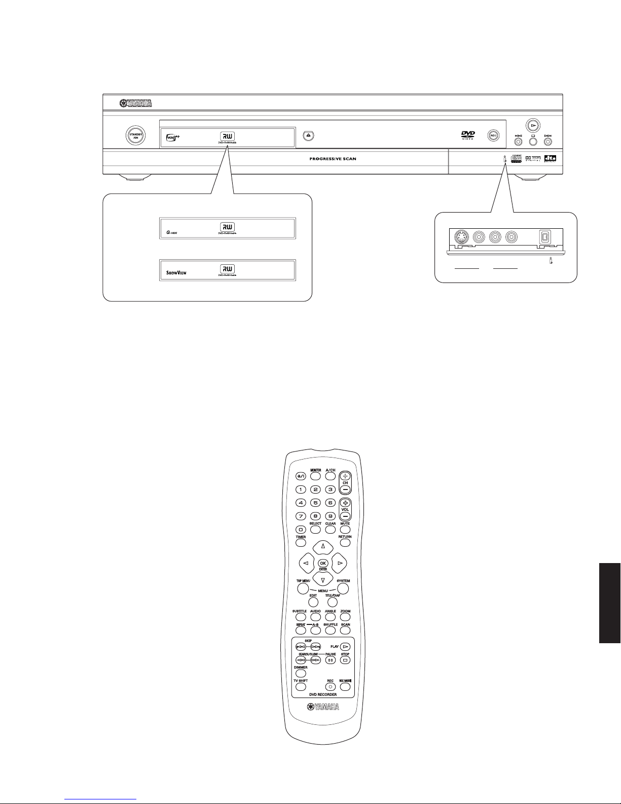
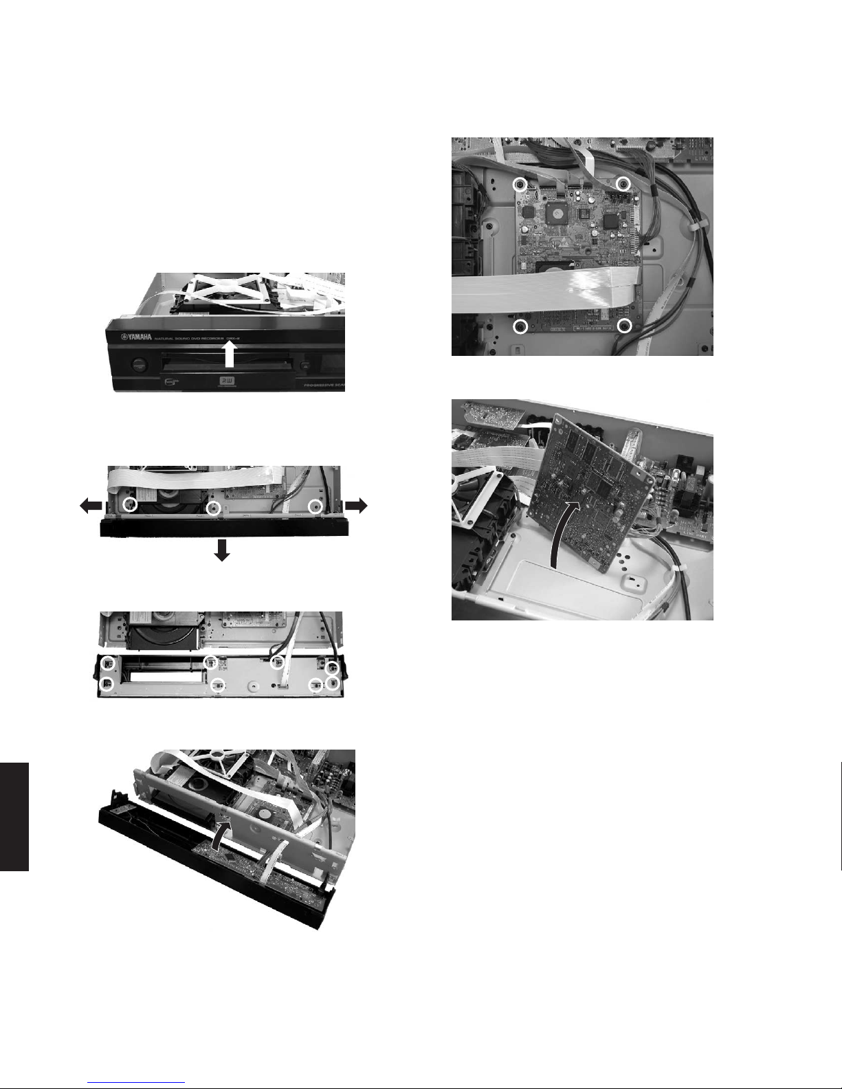
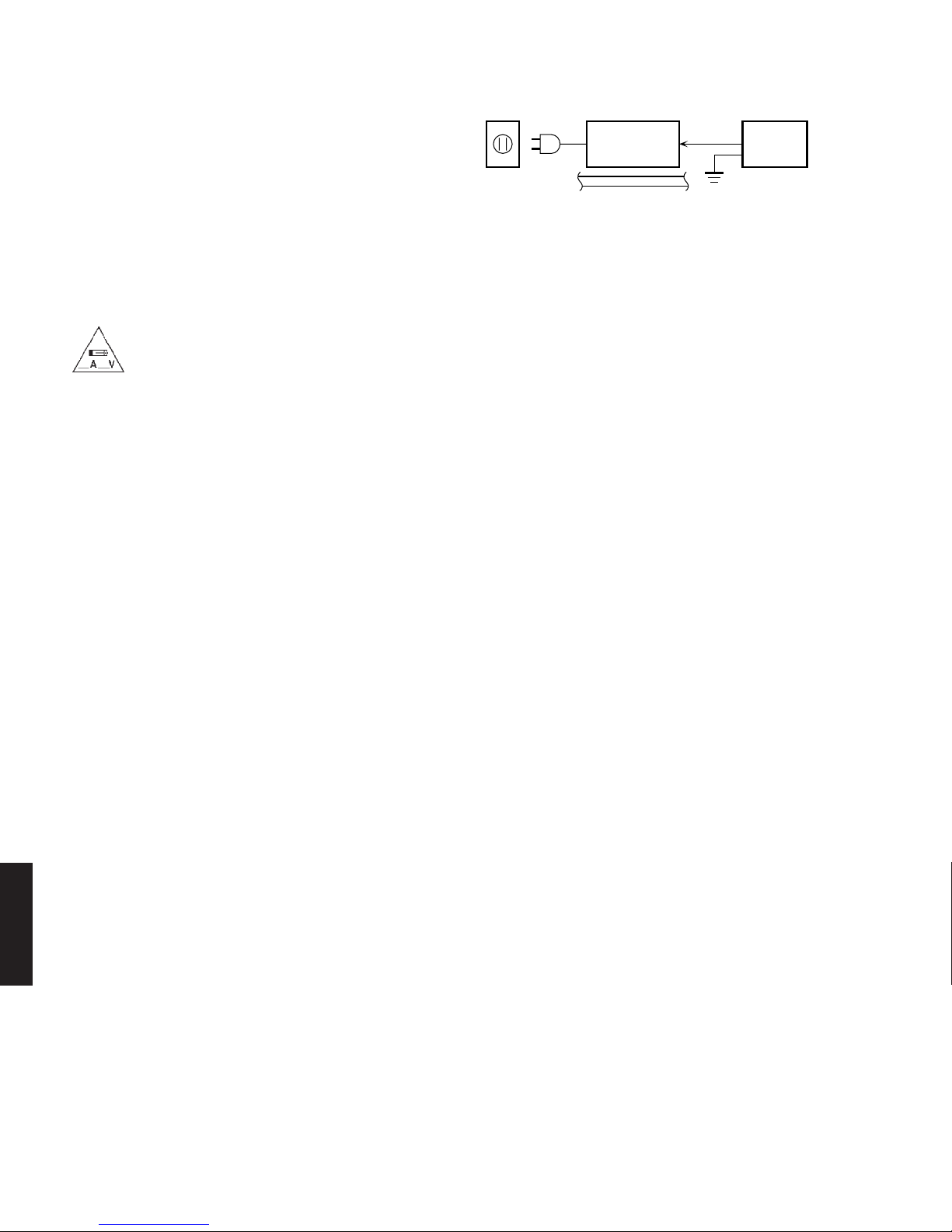
Yamaha DRX-2 User manual

DRX-2
DRX-2
1
SERVICE MANUAL
DVD RECORDER
DRX-2
100878
■CONTENTS
TO SERVICE PERSONNEL ...................................... 2~4
PREVENTION OF ELECTRO STATIC DISCHARGE ... 4
LOCALE MANAGEMENT INFORMATION ................... 4
FRONT PANELS ............................................................ 5
REMOTE CONTROL PANEL ........................................ 5
REAR PANELS .............................................................. 6
SPECIFICATIONS...................................................... 6~8
DISASSEMBLY PROCEDURES ............................. 9~11
DIAGNOSTIC SOFTWARE ................................... 12~94
ALIGNMENTS ........................................................ 95~97
CIRCUIT DESCRIPTIONS ................................... 98~114
ABBREVIATION LIST ....................................... 115~118
IC DATA ............................................................. 119~126
BLOCK DIAGRAM ..................................................... 127
WIRING DIAGRAM .................................................... 128
WAVEFORMS .................................................... 129~130
PRINTED CIRCUIT BOARD .............................. 131~149
SCHEMATIC DIAGRAM .................................... 150~177
PARTS LIST ....................................................... 178~189
IMPORTANT NOTICE
This manual has been provided for the use of authorized YAMAHA Retailers and their service personnel.
It has been assumed that basic service procedures inherent to the industry, and more specifically YAMAHA Products, are already
known and understood by the users, and have therefore not been restated.
WARNING: Failure to follow appropriate service and safety procedures when servicing this product may result in personal
injury, destruction of expensive components, and failure of the product to perform as specified. For these reasons,
we advise all YAMAHA product owners that any service required should be performed by an authorized
YAMAHA Retailer or the appointed service representative.
IMPORTANT: The presentation or sale of this manual to any individual or firm does not constitute authorization, certification or
recognition of any applicable technical capabilities, or establish a principle-agent relationship of any form.
The data provided is believed to be accurate and applicable to the unit(s) indicated on the cover. The research, engineering, and
service departments of YAMAHA are continually striving to improve YAMAHA products. Modifications are, therefore, inevitable
and specifications are subject to change without notice or obligation to retrofit. Should any discrepancy appear to exist, please
contact the distributor's Service Division.
WARNING: Static discharges can destroy expensive components. Discharge any static electricity your body may have
accumulated by grounding yourself to the ground buss in the unit (heavy gauge black wires connect to this buss).
IMPORTANT: Turn the unit OFF during disassembly and part replacement. Recheck all work before you apply power to the unit.
P.O.Box 1, Hamamatsu, Japan

DRX-2
DRX-2
2
WALL
OUTLET
EQUIPMENT
UNDER TEST
AC LEAKAGE
TESTER OR
EQUIVALENT
INSULATING
TABLE
WARNING: CHEMICAL CONTENT NOTICE!
The solder used in the production of this product contains LEAD. In addition, other electrical/electronic and /or plastic
(where applicable) components may also contain traces of chemicals found by the California Health and Welfare Agency
(and possibly other entities) to cause cancer and/or birth defects or other reproductive harm.
DO NOT PLACE SOLDER, ELECTRICAL/ELECTRONIC OR PLASTIC COMPONENTS IN YOUR MOUTH FOR ANY REA-
SON WHATSOEVER!
Avoid prolonged, unprotected contact between solder and your skin! When soldering, do not inhale solder fumes or expose
eyes to solder/flux vapor!
If you come in contact with solder or components located inside the enclosure of this product, wash your hands before
handling food.
■TO SERVICE PERSONNEL
1. Critical Components Information
Components having special characteristics are marked s
and must be replaced with parts having specifications equal
to those originally installed.
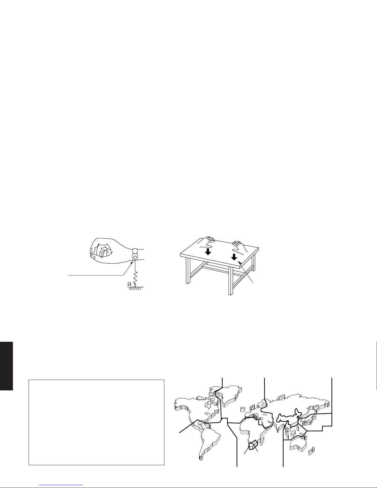
2. Leakage Current Measurement (For 120V Models Only)
When service has been completed, it is imperative to verify
that all exposed conductive surfaces are properly insulated
from supply circuits.
●Meter impedance should be equivalent to 1500 ohm shunted
by 0.15µF.
CAUTION
1001 (ANALOG P.C.B.): FOR CONTINUED PROTECTION AGAINST RISK OF FIRE, REPLACE ONLY WITH SAME TYPE 125mA, 250V FUSE.
1300 (ANALOG P.C.B.): FOR CONTINUED PROTECTION AGAINST RISK OF FIRE, REPLACE ONLY WITH SAME TYPE 2.5A, 250V FUSE.
1303 (ANALOG P.C.B.): FOR CONTINUED PROTECTION AGAINST RISK OF FIRE, REPLACE ONLY WITH SAME TYPE 1.0A, 250V FUSE.
1304 (ANALOG P.C.B.): FOR CONTINUED PROTECTION AGAINST RISK OF FIRE, REPLACE ONLY WITH SAME TYPE 4.0A, 250V FUSE.
1306 (ANALOG P.C.B.): FOR CONTINUED PROTECTION AGAINST RISK OF FIRE, REPLACE ONLY WITH SAME TYPE 125mA, 250V FUSE.
1307 (ANALOG P.C.B.): FOR CONTINUED PROTECTION AGAINST RISK OF FIRE, REPLACE ONLY WITH SAME TYPE 1.0A, 250V FUSE.
1308 (ANALOG P.C.B.): FOR CONTINUED PROTECTION AGAINST RISK OF FIRE, REPLACE ONLY WITH SAME TYPE 500mA, 250V FUSE.
1309 (ANALOG P.C.B.): FOR CONTINUED PROTECTION AGAINST RISK OF FIRE, REPLACE ONLY WITH SAME TYPE 800mA, 250V FUSE.
1505 (DIGITAL P.C.B.): FOR CONTINUED PROTECTION AGAINST RISK OF FIRE, REPLACE ONLY WITH SAME TYPE 1.0A, 125V FUSE.
1506 (DIGITAL P.C.B.): FOR CONTINUED PROTECTION AGAINST RISK OF FIRE, REPLACE ONLY WITH SAME TYPE 1.0A, 125V FUSE.
1507 (DIGITAL P.C.B.): FOR CONTINUED PROTECTION AGAINST RISK OF FIRE, REPLACE ONLY WITH SAME TYPE 1.0A, 125V FUSE.
CAUTION
1001 (ANALOG P.C.B.): REPLACE WITH SAME TYPE 125mA, 250V FUSE.
1300 (ANALOG P.C.B.): REPLACE WITH SAME TYPE 2.5A, 250V FUSE.
1303 (ANALOG P.C.B.): REPLACE WITH SAME TYPE 1.0A, 250V FUSE.
1304 (ANALOG P.C.B.): REPLACE WITH SAME TYPE 4.0A, 250V FUSE.
1306 (ANALOG P.C.B.): REPLACE WITH SAME TYPE 125mA, 250V FUSE.
1307 (ANALOG P.C.B.): REPLACE WITH SAME TYPE 1.0A, 250V FUSE.
1308 (ANALOG P.C.B.): REPLACE WITH SAME TYPE 500mA, 250V FUSE.
1309 (ANALOG P.C.B.): REPLACE WITH SAME TYPE 800mA, 250V FUSE.
1505 (DIGITAL P.C.B.): REPLACE WITH SAME TYPE 1.0A, 125V FUSE.
1506 (DIGITAL P.C.B.): REPLACE WITH SAME TYPE 1.0A, 125V FUSE.
1507 (DIGITAL P.C.B.): REPLACE WITH SAME TYPE 1.0A, 125V FUSE.
ATTENTION
1001 (ANALOG P.C.B.): UTILISER UN FUSIBLE DE RECHANGE DE MEME TYPE DE 125mA, 250V.
1300 (ANALOG P.C.B.): UTILISER UN FUSIBLE DE RECHANGE DE MEME TYPE DE 2.5A, 250V.
1303 (ANALOG P.C.B.): UTILISER UN FUSIBLE DE RECHANGE DE MEME TYPE DE 1.0A, 250V.
1304 (ANALOG P.C.B.): UTILISER UN FUSIBLE DE RECHANGE DE MEME TYPE DE 4.0A, 250V.
1306 (ANALOG P.C.B.): UTILISER UN FUSIBLE DE RECHANGE DE MEME TYPE DE 125mA, 250V.
1307 (ANALOG P.C.B.): UTILISER UN FUSIBLE DE RECHANGE DE MEME TYPE DE 1.0A, 250V.
1308 (ANALOG P.C.B.): UTILISER UN FUSIBLE DE RECHANGE DE MEME TYPE DE 500mA, 250V.
1309 (ANALOG P.C.B.): UTILISER UN FUSIBLE DE RECHANGE DE MEME TYPE DE 800mA, 250V.
1505 (DIGITAL P.C.B.): UTILISER UN FUSIBLE DE RECHANGE DE MEME TYPE DE 1.0A, 125V.
1506 (DIGITAL P.C.B.): UTILISER UN FUSIBLE DE RECHANGE DE MEME TYPE DE 1.0A, 125V.
1507 (DIGITAL P.C.B.): UTILISER UN FUSIBLE DE RECHANGE DE MEME TYPE DE 1.0A, 125V.
●Leakage current must not exceed 0.5mA.
●Be sure to test for leakage with the AC plug in both polarities.
THE DVD RECORDER SHOULD NOT BE ADJUSTED OR REPAIRED BY ANYONE EXCEPT PROPERLY QUALIFIED
SERVICE PERSONNEL.

DRX-2
DRX-2
3
CAUTION:
Visible and invisible laserradiation
when open. Avoid exposure to beam.
CLASS 1
LASER PRODUCT
CAUTION:
Visible and invisible laser radiation
when open. Avoid exposure to beam.
Laser Diode Properties
Type: InGaAIP Semiconductor laser (DVD)
AlGaAs Semiconductor laser (CD)
Wave length: 660 nm (DVD)
780 nm (CD)
Output Power: 20 mW (DVD writing)
(out of objective) 0.8 mW (DVD reading)
0.3mW (CD reading)
Beam divergence: 82 degrees (DVD)
54 degrees (CD)
VARO! : AVATTAESSA JA SUOJALUKITUS OHITETTAESSA OLET ALTTIINA NÄkymÄTTÖMÄLLE LASER-
SÄTEILYLLE. ÄLÄ KATSO SÄTEESEEN.
VARNING! : OSYNLIG LASERSTRÅLNING NÄR DENNA DEL ÄR ÖPPNAD OCH SPÄRREN ÄR URKOPPLAD.
BETRAKTA EJ STRÅLEN.
WARNING
The use of optical instruments with this product will
increase eye hazard.
Repair handling should take place as much as possible
with a disc loaded inside the player.
WARNING LOCATION:
Top of the DVDR Mechanism
WARNING: Laser Safety
This product contains a laser beam component. This component may emit invisible, as well as visible radiation, which may
cause eye damage. To protect your eyes and skin from laser radiation, the following precautions must be used during
servicing of the unit.
1) When testing and/or repairing any component within the product, keep your eyes and skin more than 30 cm away from
the laser pick-up unit at all times. Do not stare at the laser beam at any time.
2) Do not attempt to readjust, disassemble or repair the laser pick-up, unless noted elsewhere in this manual.
3) CAUTION: Use of controls, adjustments or performance of procedures other than those specified herein may result in
hazardous radiation exposure.
Laser Emitting conditions:
1) When the Top Cover is removed and the "STANDBY/ON" SW is turned to the "ON" position, the laser component will emit
a beam for several seconds to detect if a disc is present. During this time (5 - 10 sec.) the laser may radiate through the
lens of the laser pick-up unit. Do not attempt any servicing during this period!
If no disc is detected, the laser will stop emitting the beam. When a disc is loaded, you will not be exposed to any laser
emissions.
2) The laser power level can be adjusted with the VR on the pick-up PWB. However, this level has been set by the factory prior to
shipping from the factory. Do not adjust this laser level control unless instruction is provided elsewhere in this manual.
Adjustment of this control can increase the laser emission level from the device.

DRX-2
DRX-2
4
1
2
4
2
5
5
4
2
6
3
5
■LOCALE MANAGEMENT INFORMATION
Locale Management Information : This DVD recorder is designed and manufactured to respond to the Locale Management
Information that is recorded on the DVDR disc. If the Locale number described on the DVDR disc does not correspond to the
Locale number of this DVD recorder, this DVD recorder cannot play this disc.
This product incorporates copyright protection
technology that is protected by method claims of
certain U.S. patents and other intellectual
property rights owned by Macrovision
Corporation and other rights owners. Use of this
copyright protection technology must be
authorized by Macrovision Corporation, and is
intended for home and other limited viewing uses
only unless otherwise authorized by Macrovision
Corporation. Reverse engineering or
disassembly is prohibited.
■PREVENTION OF ELECTRO STATIC DISCHARGE
The laser diode in the DVDR mechanism may be damaged due to static electricity from clothes or the human body. Use
caution to prevent electrostatic damage when servicing or handling the DVDR mechanism.
1. Grounding for electrostatic damage prevention
Some devices, such as the DVD recorder, use an optical pickup (laser diode) that will be damaged by static electricity in the
working environment. Only attempt service after ensuring that all grounding procedures have been completed.
1. Worktable grounding
Put a grounded conductive material (sheet) or iron sheet on the area where the optical pickup is placed.
2. Human body grounding
Use an anti-static wrist strap to discharge the static electricity from your body.
1M Conductive material
(sheet) or iron sheet
Anti-static wrist strap
2. Handling Precautions for DVDR mechanism
1. Handle the DVDR mechanism gently, as it is an extremely high-precision assembly.
2. The flexible cable lines may break if an excessive force is applied to it. Use caution when handling the cable.
3. The semi-fixed resistor for laser power adjustment should not be adjusted. Do not turn the resistor.
Warning for power supply
The primary side of the power supply carries live mains voltage when the player is connected to the mains even
when the player is switched off !
This primary area is not shielded so it is possible to touch copper tracks and/or components when servicing the player.
Service personnel have to take precautions to prevent touching this area or components in this area .
The primary side of the power supply has been indicated with a lightening stroke and a stripe-marked print on the printed
wiring board
Note:
The screws on the DVDR mechanism may never be touched, removed or re-adjusted.
Handle the DVDR mechanism with care when the unit has to be exchanged!
The DVDR mechanism is very sensitive for dropping or giving shocks.

DRX-2
DRX-2
5
■FRONT PANELS
■REMOTE CONTROL PANEL
A model
G model
NATURAL
SOUND
DVD
RECORDER
DRX-2
U model
S VIDEO VIDEO
CAM 1 CAM 2
L AUDIO R DV IN

DRX-2
DRX-2
6
■REAR PANELS
U model
A model
■SPECIFICATIONS
DISC FORMATS SUPPORTED
Disc type Playback Recording
DVD+RW ••
DVD+R ••
DVD-RW (Video mode)
•—
DVD-R •—
DVD-Video •—
SVCD •—
Video CD •—
Audio CD •—
CD-R •—
CD-RW •—
RECORDABLE DISC FORMATS
Medium DVD+RW: Phase-Change ReWritable
DVD+R: dye-based
Diameter 12 cm
Capacity (single side) 4.7 Gbyte
Recording time M1 60’9.72 Mbit/s
M2 120’5.07 Mbit/s
M2x 150’4.06 Mbit/s
M3 180’3.38 Mbit/s
M4 240’2.54 Mbit/s
M6 360' 1.69 Mbit/s
Apparatus Claims of U.S. Patent Nos.
4.631.603, 4.577.216, 4.819.098, 4.907.093
6.466.734, 6.430.359, 6.091.882,
6.049.652, 5.335.079, 5.307.173
licensed for limited viewing uses only.
G model

DRX-2
DRX-2
7
TV Standard PAL NTSC
Scan Frequency 50Hz 60Hz
Number of Lines 625 525
Playback ••
Recording ••
Internal Tuner •–
VIDEO RESOLUTION 50Hz 60Hz
DVD-Video/DVD+RW/DVD+R(M1/M2/M2x)
•Horiz. Resolution 720 pixels1720 pixels1
•Vertical Resolution 576 lines 480 lines
DVD+RW_DVD+R(M3/M4/M6)
•Horiz. Resolution 360 pixels2360 pixels2
•Vertical Resolution 576 lines 480 lines
VCD
•Horiz. Resolution 352 pixels 352 pixels
•Vertical Resolution 288 lines 288 lines
1equivalent to 500 lines on your TV
2equivalent to 250 lines on your TV
VIDEO PERFORMANCE
DA Converter 10-bit
AD Converter 9-bit
Signal Handling Components
Video Output 1 Vpp into 75 ohms
S-video Output Y: 1 Vpp into 75 ohms
C: 0.286 Vpp into 75 ohms (U, A models)
C: 0.300 Vpp into 75 ohms (G model)
Component Output Y: 1Vpp into 75 ohms (U, A models)
Pb: 0.7 Vpp into 75 ohms (U, A models)
Pr: 0.7 Vpp into 75 ohms (U, A models)
RGB Output 0.7 Vpp into 75 ohms (G model)
AUDIO FORMAT
Compressed Digital Playback Recording
•Dolby Digital Multi-channel 2-channel
(AC-3) 16 bit, fs 48 kHz
•DTS Multi-channel —
•MPEG1 2-channel —
SPdif
•PCM 2-channel 2-channel
16, 20, 24 bit 16 bit, fs 48 kHz
fs 48 kHz
AUDIO PERFORMANCE
DA Converter 24-bit
AD Converter 16-bit
DVD fs 96 kHz 4 Hz - 44 kHz
fs 48 kHz 4 Hz - 22 kHz
Video CD fs 44.1 kHz 4 Hz - 20 kHz
Audio CD fs 44.1 kHz 4 Hz - 20 kHz
FRONT CONNECTIONS
i.LINK DV IEEE 1394 4-pin
S-video Input Hosiden 4-pin
Video Input Cinch (yellow)
Audio Left/Right Input Cinch (white/red)
REAR CONNECTIONS
Component Video Input
Cinch (green/blue/red)
Component Video Output
Cinch (green/blue/red)
S-video Input Hosiden 4-pin (U, A models)
S-video Output Hosiden 4-pin
Video Input Cinch (yellow) (U, A model)
Video Output Cinch (yellow)
scart 1
CVBS, S-video/RGB-out, Decoder (G model)
scart 2
CVBS, S-video/RGB-in, Decoder (G model)
Audio L/R Input Cinch (white/red) (U, A models)
Audio L/R Output Cinch (white/red)
Digital Audio Output 1 coaxial, 1 optical
IEC958 for CDDA / LPCM
IEC1937 for MPEG2, Dolby Digital (U, A models)
IEC1937, Dolby Digital, DTS (G model)
RF Antenna Input Coaxial 75 ohms
RF TV Output Coaxial 75 ohms
Power Standard (IEC type)
POWER SUPPLY
Power Supply
U model 120V, 60Hz
A, G models 220 - 240V, 50 Hz
Power Consumption Operation 27 W
Low-power standby 3 W
CABINET
Dimensions (WxHxD)
435 x 82 x 347 mm (17-1/8" x 3-1/4" x 13-11/16")
Net Weight 4.0 kg (8 lbs. 13 oz.)
OPERATING ENVIRONMENT
Operating Position
maximum 10 degree inclination in all directions
Ambient Temperature 15 –35 °C (59 –95 °F)
Humidity 25 –75 %
ACCESSORIES
- Remote Control x 1
- Battery x 2
- Power Cable x 1
- SCART Cable x 1 (G model)
- Audio Pin Cable (2P) x 1 (U, A models)
- Video Cable (1P) x 1 (U, A models)
- RF Cable for NAFTA x 1 (U model)
- RF Cable for PAL x 1 (A, G models)
- Pin Cable (3P) x 1 (U, A models)
- DVD+RW Disc x 1 (U, A models)
* Specifications are subject to change without notice due
to product improvements.
U ........ U.S.A. model A ........ Australian model
G ........ European model

DRX-2
DRX-2
8
Simple programming system for DVD
recorders. Simply enter the number
code associated with your television
program. This number is located in your
television listings magazine.
Manufactured under license from Dolby Laboratories.
“Dolby”, “Pro Logic”and the double-D symbol are trademarks
of Dolby Laboratories. Confidential Unpublished Works.
©1992 1997 Dolby Laboratories,Inc. All rights reserved.
“DTS”and “DTS Digital Out”are trademarks of Digital Theater
Systems, Inc.
This product incorporates copyright protection technology
that is protected by method claims of certain U.S.patents and
other intellectual property rights owned by Macrovision
Corporation and other rights owners.
Use of this copyright protection technology must be
authorized by Macrovision Corporation, and is intended for
home and other limited viewing uses only unless otherwise
authorized by Macrovision Corporation. Reverse engineering
or dis-assembly is prohibited.

DRX-2
DRX-2
9
See exploded view for item numbers
mounting
demounting
2.2 mm
T8
2.7 mm
T10
When disassembling, use the special screw driver with
tip shape in figure.
Front Panel Unit
⇒ Open the tray and remove the
tray lid 70
⇒ Remove 3 screws 201
(front panel unit → frame)
⇒ Unlock the front panel unit
from the frame by releasing 2
snaps on left and right
⇒ Remove 8 screws 205 to
remove the plate front
Analog Board 1001
⇒ Remove the connections
⇒ Remove 2 screws 201
and 7 (U, A models) or 3
(G model) screws 202
(board → rear panel)
⇒ Remove 3 screws 201
and screw 200
(board → frame)
⇒ Remove screw safety
holder 145
⇒ Demount the board
DVDR MECHANISM 1007
⇒ Remove the connections
⇒ Open the tray and remove the tray lid 70
⇒ Remove 4 screws 202
(DVDR Mechanism 1007 → support
bracket)
⇒ Demount the DVDR Mechanism
Manual opening of tray and removal of
tray lid 70
In case the loader is defective and cannot
be opened electrically, you can open the
tray as follows:
⇒ It is possible to unlock the tray by means
of a screwdriver via a slot in the front and
frame at the underside.
Push the white pin of the slider at the
underside of the DVDR Mechanism to the
right (seen from the front)
⇒ Open the unlocked tray.
IOE Board 1005
⇒ Remove 2 screws 202 and screw 201
(IOE board → rear panel)
⇒ Demount the board
Digital Board 1002
⇒ Remove the connections
⇒ Remove 4 screws 201
(Digital board → frame)
⇒ Demount the board
Display Board 1004
⇒ Remove 2 screws 205
(board → front panel ass'y 1)
⇒ Remove 2 screws 209 of DV
input cable
⇒ Demount the board
Cover 300
⇒ Remove 9 screws 200
⇒ Lift the cover to remove
FrFront Pont PanelanelFront Panel
■DISASSEMBLY PROCEDURES

DRX-2
DRX-2
10
●Dismantling and Assembly of the Set
For item numbers please see the exploded views.
1. Front
a. After removing the top cover, remove tray lid 70. (Fig. 1)
b. Remove the 3 screws 201. (Fig. 2)
c. Release the 2 snap hooks on the sides and remove the
front panel unit. (Fig. 2)
d. Remove the 8 screws 205 to remove the front plate.
(Fig. 3 and 4)
1
Fig. 1
222
33
4
Fig. 2
5
Fig. 3
6
Fig. 4
2. Digital Board
a. Remove the 4 screws 201. (Fig. 5)
b. Turn the PCB in the service position. (Fig. 6)
11
1
1
Fig. 5
2
Fig. 6

DRX-2
DRX-2
11
3. DVDR Mechanism
a. Remove the 4 screws 202. (Fig. 7)
b. Turn the DVDR mechanism in the service position. (Fig. 8)
11
1
1
Fig. 7
2
Fig. 8
4. Analog Board
a. Remove the 7 screws 200 and 201. (Fig. 9)
b. Remove screw safety holder 145. (Fig. 9)
c. Unlock the 2 snaps hooks on the left and right. (Fig. 10)
d. Turn the PCB in the service position. (Fig. 11)
111
1
1
1
1
2
(U, A models)
Fig. 9
33
(U, A models)
Fig. 10
4
(U, A models)
Fig. 11

DRX-2
DRX-2
12
Hold key <PLAY> pressed
while you plug the recorder
Unplug the power cord
During the test, the following display
is shown: the counter counts down
from the number of nuclei to be run
before the test finishes. Example:
SET O.K.?
YES
NO
To exit DEALER SCRIPT, unplug the power cord
Due to the complexity of the DVD recorder, the time to find
a defect in the recorder can become long. To reduce this
time, the recorder has been equipped with Diagnostic and
Service software (DS). The DS offers functionality to
diagnose the DVDR hardware and tests the following:
•Interconnections between components
•Accessibility of components
•Functionality of the audio and video paths
This functionality can be accessed via several interfaces:
1. End user/Dealer script interface
2. Player script interface
1. End User/Dealer Script Interface
1.1 Description
The End user/Dealer script interface gives a diagnosis on
a stand alone DVD recorder; no other equipment is
needed. During this mode, a number of hardware tests
(nuclei) are automatically executed to check if the recorder
is faulty. The diagnosis is simply a "fail" or "pass"
message. If the message "FAIL" appears on the display,
there is apparently a failure in the recorder. If the message
"PASS" appears, the nuclei in this mode have been
executed successfully. There can be still a failure in the
recorder because the nuclei in this mode don't cover the
complete functionality of the recorder.
■DIAGNOSTIC SOFTWARE
1.2 Contents
1.3 Contents for sets with Digital Board Chrysalis
Included tests: 1. DS_ANAB_COMMUNICATIONECHO_NUC
2. DS_DCB_COMMUNICATIONECHO_NUC
3. DS_BROM_COMMUNICATION_NUC
4. DS_SYS_SETTINGSDISPLAY_NUC
5. DS_CHR_DEVTYPEGET_NUC
6. DS_CHR_INT_PIC_NUC
7. DS_CHR_DMA_NUC
8. DS_BROM_WRITEREAD_NUC
9. DS_NVRAM_COMMUNICATION_NUC
10. DS_NVRAM_WRITEREAD_NUC
11. DS_SDRAM_WRITEREADFAST_NUC
12. DS_FLASH_WRITEREAD_NUC
13. DS_FLASH_CHECKSUMPROGRAM_NUC
14. DS_SYS_HARDWAREVERSIONGET_NUC
15. DS_VIP_DEVTYPEGET_NUC
16. DS_VIP_COMMUNICATION_NUC
17. DS_DVIO_LINKDEVTYPEGET_NUC
18. DS_DVIO_PHYDEVTYPEGET_NUC
19. DS_DVIO_LINKCOMMUNICATION_NUC
20. DS_DVIO_PHYCOMMUNICATION_NUC
21. DS_PSCAN_COMMUNICATIONDENC_NUC
22. DS_PSCAN_COMMUNICATIONDEINTERLACER_NUC
23. DS_BE_COMMUNICATIONECHO_NUC
24. DS_ANAB_COMMUNICATIONIICNVRAM_NUC
25. DS_ANAB_COMMUNICATIONIICTUNER_NUC
26. DS_ANAB_COMMUNICATIONIICSOUNDPROCESSOR_NUC
27. DS_ANAB_COMMUNICATIONIICAVSELECTOR_NUC
28. DS_ANAB_CHECKSUMPROGRAM_NUC
Fig. A
The End use/Dealer script executes all diagnostic nuclei
that do not need any user interaction and are meaningful
on a standalone DVD recorder.

DRX-2
DRX-2
13
UNPLUG THE RECORDER
IF TRADE MODE OFF
PRESS 2 KEYS
SIMULTANEOUSLY
PLUG THE RECORDER
RECORDER IS IN TRADE MODE
WHEN PRESSING FRONT
KEYS, THE RECORDER
DOESN'T RESPOND
<STOP> + <OPEN/CLOSE>
UNPLUG THE RECORDER
IF TRADE MODE ON
PRESS 2 KEYS
SIMULTANEOUSLY
PLUG THE RECORDER
RECORDER IS IN NORMAL MODE
WHEN PRESSING FRONT
KEYS, THE RECORDER
WILL RESPOND
<STOP> + <OPEN/CLOSE>
1.4 Error Log
Explanation:
The application errors will be logged in the NVRAM. The
maximum number of error bytes that will be visible is 19.
The last reported error is shown as DN D0000000, the
oldest visible error as D0000000 UP and the errors in
between as DN D0000000 UP. DN stands for DOWN, UP
stands for UPWARDS. The shown error codes are
identical to the Nuclei Error Codes (paragraph 3).
1.5 Trade Mode
TRADE MODE
When the recorder is in Trade Mode, the recorder
cannot becontrolled by means of the front key
buttons, but only by means of the remote control.
1.6 Virgin mode
If you want that the recorder starts up in Virgin mode,
follow this procedure:
•Unplug the recorder
•plug the recorder again while you keep the STANDBY/
ON key pressed
•the set starts up in Virgin mode.
Fig. B
2. Menu and Command Mode Interface
2.1 Nuclei Numeration
Each nucleus has a unique number of four digits. This
number is the input of the command mode.
[ XX YY ]
Nucleus number
Nucleus group number
Fig. 1
The following groups are defined for Digital Board 1.5,
Empress:
Group number Group name
0 Basic / Scripts
1 Host decoder (Sti5505 and memory)
2 Audio / video encoder (DVDR only)
3 VSM (DVDR only)
4 NVRAM
5 Front Panel
6 DVDR Mechanism
7 Analog board (DVDR only)
8 DVIO (DVDR only)
9 Loop nuclei (DVDR only)
10 Library sub nuclei (I2C nuclei)
11 User interface
12 Furore (SACD only)
13 DAC (SACD only)
The following groups are defined for Digital Board
Chrysalis:
Group number Group name
0 Basic/Scripts
1 Chrysalis
2 Boot EEPROM
3 NVRAM
4 SDRAM
5 Flash
6 Video Input Processor
7 DVIO
8 Progressive Scan
9 DVDR Mechanism
10 Display and Control Board
11 Analog Board
12 System

DRX-2
DRX-2
14
2.2 Error Handling
Each nucleus returns an error code. This code contains
six numerals, which means:
[ XX YY ZZ ]
Error code
Nucleus number
Nucleus group number
Fig. 2
The nucleus group numbers and nucleus numbers are the
same as above.
2.3 Command Mode Interface
Set-Up Physical Interface Components
Hardware required:
•Service PC
•one free COM port on the Service PC
•special cable to connect DVD recorder to Service PC
The service PC must have a terminal emulation program
(e.g. Hyperterminal) installed and must have a free COM
port (e.g. COM1). Activate the terminal emulation program
and check that the port settings for the free COM port are:
19200 bps, 8 data bits, no parity, 1 stop bit and no flow
control. The free COM port must be connected via a
special cable to the RS232 port of the DVD recorder. This
special cable will also connect the test pin, which is
available on the connector, to ground (i.e. activate test
pin).
Code number of PC interface cable: 3122 785 90017
(AAX57390)
Activation Digital Board Chrysalis
1. Pull the mains cord from the recorder and reconnect it
again (reboot).
2. The next welcome message will appear on the PC:
Welcome screen D&S program
Fig. 3
Now, the prompt 'DS:>' will appear. The diagnostic
software is now ready to receive commands. The
commands that can be given are the numbers of the
nuclei. If you see above shown screen, continue with
paragraph 'Nuclei Codes'.
3. It is possible that the next message will appear when
starting the DVD+RW for the first time
Error message D&S program
Fig. 4
In this case, the boot EEPROM of the Chrysalis Digital
Board does not contain the required string with the
hardware information. To update the Digital Board with the
correct string, nucleus 1226 must be executed.
Before doing so, one must generate this string. In order to
generate the correct parameters, an MS Windows utility,
called "dbstring.exe", is available (contact your Philips
regional service support for this). For a detailed
description, see next section 'String Generation'.
String Generation
4. Browse to the directory with the Diagnostics software
(e.g. type 'cd c:\ds\'), and execute the 'dbstring.exe'
application.
Opening screen 'dbstring' program
Fig. 5
5. Type '1' for a list of DVD recorders, or '2' for a list of
Chrysalis Digital boards. In this example, '2' is entered.

DRX-2
DRX-2
15
Board overview
Fig. 6
6. You now are asked to enter an ID of the board that must
be programmed. Type a number, e.g. '6' followed by
'Enter'.
9. Execute nucleus 1226 with the string (paste with 'Edit'
> 'Paste to host').
Nucleus 1226 execution with string
Fig. 9
10. To check if the hardware info is filled correctly, you can
execute nucleus 1228.
Nucleus 1228 info example
Fig. 10
11. Exit the 'Terminal' program.
12. Reboot the DVD recorder to allow the software to start.
Browse to the directory with the Diagnostics software
(e.g. type 'cd c:\ds\'), and execute the 'dbstring.exe'
application.
Board periphery
Fig. 7
7. Confirm the choice by typing 'y' followed by 'Enter'. Now
press any key to return to the prompt.
8. A text file called 'DBSTRING.TXT' is created, which
contains the parameters that are necessary for nucleus
1226. Copy this string from the text-file (e.g. by using
'Ctrl C').
Example of the string
Fig. 8

DRX-2
DRX-2
16
Nucleus Name DS_CHR_TestImageOn
Nucleus Number 101
Description Generates a test-image of a selected video standard on selected video output on the digital
board. When no input is given, the default values will be used. Use nucleus
DS_ANAB_VideoRouting to route the video signal on the analog board output
Command overview Digital Board Chrysalis
Below you will find an overview of the nuclei, their
numbers, and their error codes. This overview is
preliminary and subject to modifications.
Chrysalis (CHR)
Nucleus Name DS_CHR_DevTypeGet
Nucleus Number 100
Description Sends the device ID and the module ids and revisions of the PNX7100 (Chrysalis) to the
stdout port.
Technical - Determine the codec ID by means of comparing version ids of the modules.
- Read the module-id register from every module.
Execution Time Less than 1 second.
User Input None
Error Number Description
10000 Getting the information succeeded
10001 Wrong codec ID detected
Example DS:> 100
Device ID 7100
Codec ID PNX7100_MF2
F-BCU (0x0102) 1.0 INTC (0x011d) 1.0 PCI-XIO(0x0113) 1.0
SIF(0x013b) 1.0 EJTAG (0x0104) 0.0 S-BCU (0x0102) 1.0
BOOT (0x010a) 1.0 CONFIG (0x013f) 1.0 RESET (0x0123) 1.0
DEBUG (0x0116) 0.0 UART0 (0x0107) 0.1 UART1 (0x0107) 0.1
UART2 (0x0107) 0.1 UART3 (0x0107) 0.1 I2C0 (0x0105) 0.1
I2C1 (0x0105) 0.1 GPIO (0x013c) 1.0 SYNC (0x013a) 1.0
DISP0 (0xa015) 0.1 DISP1 (0xa00f) 0.0 OSD (0x0136) 0.1
SPU (0xa00e) 0.0 MIXER (0x0137) 1.0 DENC (0x0138) 0.1
CCIR (0x0139) 1.0 VDEC (0x0133) 0.1 PARSER (0xa00d) 0.0
DV (0xa00c) 0.0 BEI (0xa00a) 0.0 IDE (0xa009) 0.0
SGDX (0xa008)0.0 BYTE (0xa00b) 0.0 OUTPUT (0xa003) 0.0
ACOMP (0xa000) 0.0 VFE (0xa001) 0.0 VCOMP (0xa002) 0.0
SCR (0x0000) 0.0 SIFF (0xa011) 0.0 WMD (0xa010) 0.0
AUDIO0 (0xa015) 0.1 AUDIO1 (0xa00f) 0.0 PSCAN (0xa018) 0.0
010000:
Test OK @

DRX-2
DRX-2
17
Technical - Validate the user input.
- Initialise the SYNC module.
- Initialise the DISPLAY module.
- Initialise the MIXER module.
- Initialise the DENC module.
- Set the selected video standard.
- Generate the selected test image in memory.
- Start the DISPLAY module.
- Start the MIXER module.
- Start the DENC module according to the selected test image id.
Execution Time 1 second.
User Input The user has to decide which test image, video standard and video output must be used:
Test image id:
0 VERTICAL_COLOURBAR (default)
1 HORIZONTAL_COLOURBAR
2 WHITE
3 YELLOW
4 CYAN
5 GREEN
6 MAGENTA
7 RED
8 BLUE
9 BLACK
10 GRAY
Video standard:
PAL (default)
NTSC
Video output:
ALL CVBS and YC and RGB (default)
CVBS
YC
RGB
YUV
PSCAN progressive scan
Error Number Description
10100 Generating the test image succeeded.
10101 Invalid input was provided.
10102 The Chrysalis SYNC-module cannot be initialised.
10103 The Chrysalis MIXER-module cannot be initialised.
10104 The Chrysalis VPP-module cannot be initialised.
10105 The Chrysalis DENC-module cannot be initialised.
Example DS:> 101
010100:
Test OK @
DS:> 101 0 pal cvbs
010100:
Test OK @
DS:> 101 4 ntsc yc
010100:
Test OK @

DRX-2
DRX-2
18
Nucleus Name DS_CHR_TestImageOff
Nucleus Number 102
Description Switches the test-image off.
Technical - Stop the DENC module.
Execution Time Less than 1 second.
User Input None
Error Number Description
Example 10200 Stopping the test image generation succeeded
10201 The Chrysalis DENC-module failed.
DS:> 102
010200:
Test OK @
Nucleus Name DS_CHR_SineOn
Nucleus Number 103
Description Generate an audio sine signal on the audio output of the digital board.
Note: Left channel 6kHz, right channel 12 kHz sine. Make sure to route the signal first.
Technical - De-mute the analog board
- Set fifo parameters for audio
- Set the volume
- Set the I2S outputs and configuration paths
- Set the decoder mode
- Configure the DUET DSP
- Configure the PALM DSP
- Put the AC3 audio in the fifo
- Send ‘prepare’command to the audio decoder
- Send ‘play’command to the audio decoder
Execution Time Less than 1 second
User Input None
Error Number Description
10300 The sine signal was successfully generated
10301 The analog board could not be de-muted
10302 The audio decoder did not initialise
10303 The dsp2 of the audio decoder did not configure
10304 The dsp1 of the audio decoder did not configure
10305 There was a delay-error before starting
10306 Wrong input was given to the decoder function
Example DS:> 103
010300:
Test OK @
Nucleus Name DS_CHR_SineOff
Nucleus Number 104
Description Stop generating the audio sine signal
Technical - Reset the audio block of the Chrysalis
Execution Time Less than 1 second.
User Input None
Error Number Description
10400 Switching off the audio sine signal succeeded
Example DS:> 104
010400:
Test OK @

DRX-2
DRX-2
19
Nucleus Name DS_CHR_SineBurst
Nucleus Number 105
Description Generate an audio sine signal on the audio output of the digital board for 4 seconds.
Note: Left channel 6kHz, right channel 12 kHz sine with some known hick-ups
Technical - Call the DS_CHR_SineOn nucleus
- Delay for 4 seconds
- Call the DS_CHR_SineOff nucleus
Execution Time 4 seconds
User Input None
Error Number Description
10500 The sine signal burst was successfully generated
10501 The delay did not succeed during the burst
10502 The audio sine could not be generated
Example DS:> 105
010500:
Test OK @
Nucleus Name DS_CHR_MuteOn
Nucleus Number 106
Description Mute the audio outputs of the digital board
Technical - Send the ‘Mute’command to the PALM DSP
Execution Time Less than 1 second.
User Input None
Error Number Description
10600 Muting the audio succeeded
Example DS:> 106
010600:
Test OK @
Nucleus Name DS_CHR_MuteOff
Nucleus Number 107
Description De-mute the audio outputs of the digital board
Technical - Send the ‘DeMute’command to the PALM DSP
Execution Time Less than 1 second.
User Input None
Error Number Description
10700 De-muting the audio succeeded
Example DS:> 107
010700:
Test OK @

DRX-2
DRX-2
20
Nucleus Name DS_CHR_DvLedOn
Nucleus Number 108
Description Check the connection to the DV-LED on the digital board by switching it on
Technical - Write to the PIO pin to light the DV LED
Execution Time Less than 1 second.
User Input None
Error Number Description
10800 Switching the DV-LED on succeeded
10801 Switching the DV-LED on failed
Example DS:> 108
010800:
Test OK @
Nucleus Name DS_CHR_DvLedOff
Nucleus Number 109
Description Switch off the DV-LED on the digital board
Technical - Write to the PIO pin to switch off the DV LED
Execution Time Less than 1 second.
User Input None
Error Number Description
10900 Switching the DV-LED off succeeded
10901 Switching the DV-LED off failed
Example DS:> 109
010900:
Test OK @
Nucleus Name DS_CHR_MacroVisionOn
Nucleus Number 110
Description Turn on MacroVision.
Technical - Set some registers of the DENC module in the Chrysalis.
Execution Time Less than 1 second.
User Input None
Error Number Description
11000 Turning on MacroVision succeeded
11001 Turning on MacroVision failed
Example DS:> 110
011000:
Test OK @
Nucleus Name DS_CHR_MacroVisionOff
Nucleus Number 111
Description Turn off MacroVision.
Technical - Set some registers of the DENC module in the Chrysalis.
Execution Time Less than 1 second.
User Input None
Error Number Description
11100 Turning off MacroVision succeeded
11101 Turning off MacroVision failed
Example DS:> 111
011100:
Test OK @
Other manuals for DRX-2
2
Table of contents
Other Yamaha DVD Recorder manuals