manuals.online logo
Brands
  1. Home
  2. •
  3. Brands
  4. •
  5. Yamaha
  6. •
  7. Home Theater System
  8. •
  9. Yamaha YSP-4300 User manual

Yamaha YSP-4300 User manual

This Quick Reference Guide explains steps to connect external components to this unit and start playback. For detailed operation,
refer to the “Owner’s Manual” in the supplied CD-ROM.
Check that you received all of the supplied accessories referring to “Supplied accessories” of “Safety and Accessory Information”
(separate booklet). For instructions on how to operate or set the external components, refer to the owner’s manual supplied with each
component.
In this guide, the YSP-CU4300 center unit is used for illustrative purposes.
Installation Connection Settings Playback
Installing YSP-4300/YSP-3300
Quick Reference Guide English
UCABGLVFH
Center unit
• Install the center unit in the center of the left and right walls.
• Place the center unit on a TV stand in front of the TV.
Use the TV Remote Repeater function if the center unit
obstructs the remote control sensor on the TV (see page 12 of
the Owner's Manual).
Increase the height of the center unit if the TV stand is too high
for center unit installation (see page 12 of the Owner's Manual).
• The listening position (such as sofa, etc.) should be located at
the front of the center unit.
• The distance between the listening position and the center unit
should be more than 1.8 m (6 ft).
• This unit can be mounted on a wall using WALL MOUNT
BRACKET SPM-K20 (option). Refer to the SPM-K20 Install
Manual and SPM-K20 Information for YSP-CU4300/
YSP-CU3300.
Center unit Subwoofer
Subwoofer
• To prevent sound reflecting off of walls, angle the subwoofer
slightly toward the center of the room.
• When installing the subwoofer on a rack, be sure the rack is
strong enough to support the subwoofer and that it leaves
sufficient space for heat discharge.
• The center unit and subwoofer communicate wirelessly.
Subwoofer performance may be affected if the subwoofer is
placed on a metal rack, or if there is a metal plate between the
subwoofer and the center unit.
• The subwoofer can also be placed on its side (see page 13 of
the Owner's Manual).
This unit creates surround effects by reflecting sound beams off
the walls of your listening room. The arrows in the diagrams on the
right indicate the images of paths of 5-channel sound beams. To
achieve desired surround sound effects, install this unit where
there are no objects such as furniture obstructing the path of sound
beams.
1Front left channel 4Surround left channel
2Center channel 5Surround right channel
3Front right channel
Parallel installation Corner installation
Objects,
such as
furniture
Objects, such as furniture
40° to 50°
Installation Connection Settings Playback
Connection
When external devices such as a TV, Blu-ray disc player, and/or game console are connected, audio and video signals are transmitted
as shown below.
• Do not connect the power cable until all connections are completed.
• Do not use excessive force when inserting the cable plug. Doing so may damage the cable plug and/or jack.
■Connecting a TV and a Blu-ray disc player
For the cable connection, follow the procedure below.
Audio
connection
Video
connection
Audio and video
connection
This unit: Plays audio from TV broadcasts, Blu-ray discs, etc.
Game console
(HDMI compatible)
Satellite and cable TV tuner
(not HDMI compatible) TV: Plays video from TV broadcasts,
Blu-ray disc player, etc.
Blu-ray disc player
HDMI cable
HDMI cable
Optical cable
Use to connect a TV
that does not support
audio return channel
(ARC) to this unit.
Composite video cable
Optical cable
HDMI cable
1.
HDMI cable (optional)
Input the digital audio/video signals of
the Blu-ray disc player to this unit.
2.
HDMI cable (optional)
The digital video of the Blu-ray disc
player is reflected on TV.
3.
Optical cable (supplied)
Play back digital sounds of TV on this
unit. y
HDMI INPUT
123
HDMI
OUTPUT
OPTICAL
OUTPUT
Blu-ray disc player
TV
1. Remove the cap 2. Check the direction
of the plug
Video signals
Audio signals
1
2
3
y
To AC wall outlet
4.
U.S.A., Canada,
Europe, Russia, and
China models only
■Connecting a game console or satellite/cable TV tuner
Audio return channel (ARC) supported TV
• Connect an HDMI cable to the audio return channel supported jack (the jack with “ARC” indicated) on TV. In this case, you do not need
to connect an optical cable.
• Activate the HDMI control function of this unit so as to activate the audio return channel (ARC) (refer to “HDMI setup” in the Owner's
Manual).
What is audio return channel (ARC)?
A function transmits digital audio signal output from TV to this unit through an HDMI cable. By this function, an optical cable to connect TV
and this unit is not needed.
yTips
External device (example) Connecting cable
HDMI compatible
1Satellite/cable TV tuner HDMI cable (optional)
2Game console HDMI cable (optional)
3Game console HDMI cable (optional)
not HDMI compatible
4Satellite/cable TV tuner Optical cable (supplied)
Composite video cable (optional)
5Game console RCA stereo cable (optional)
Composite video cable (optional)
HDMI
OUTPUT
HDMI
OUTPUT
HDMI
OUTPUT
VIDEO
INPUT
VIDEO
INPUT
OPTICAL
OUTPUT
ANALOG
OUTPUT
RL
VIDEO
OUTPUT
VIDEO
OUTPUT
TV
Video signals
Audio signals
y
To AC wall outlet
To connect a device with an AUX output jack, connect its AUX output jack to the AUX INPUT DIGITAL (coaxial) jack on this unit via a
commercial coaxial digital audio cable.
yTip
U.S.A., Canada,
Europe, Russia, and
China models only
■Connecting the FM antenna (YSP-4300 only)
Connect the supplied FM antenna via the FM ANTENNA jack.
■Connecting the wireless subwoofer
■Preparing remote control
Install the batteries Operation range
FM antenna
A
B
C
1
2
3
LINK
A
B
C
1
2
3
LINK
Group ID switches
LINK indicator
Blinks: Establishing
connection
Lights: Connection
established
To AC wall outlet
To connect the supplied subwoofer to the center unit wirelessly, the same
group ID must be assigned to the center unit and subwoofer. The default
group ID for both components is A1, enabling wireless connection by
simply plugging the subwoofer's power cable into an electrical outlet.
When using the transmitter (YIT-W12TX)*, the same group ID must be
assigned to the center unit and subwoofer. The default group ID of
YIT-W12TX is A1.
The LINK indicator lights when the subwoofer is on and the subwoofer
and center unit are connected wirelessly.
When the center unit enters standby mode, the subwoofer and LINK
indicator turn off.
* For details of YIT-W12TX, refer to “Safety and Accessory Information”
(separate booklet).
Battery × 2
(AAA, R03, UM-4)
Pull up on the latch to
release the cover
Insert the
protrusions into
the slots and
close the cover
Within 6 m (20 ft)
Printed in Malaysia ZD75600 [En] © 2012 Yamaha Corporation
Installation Connection Settings Playback
Carrying out AUTO SETUP for appropriate surround effects
The IntelliBeam technology allows you to achieve sound adjustments that best match your listening environment. It is normal for loud
test tones to be output during the AUTO SETUP procedure. Make sure that there are no children around in the listening room while the
AUTO SETUP procedure is in progress.
1.
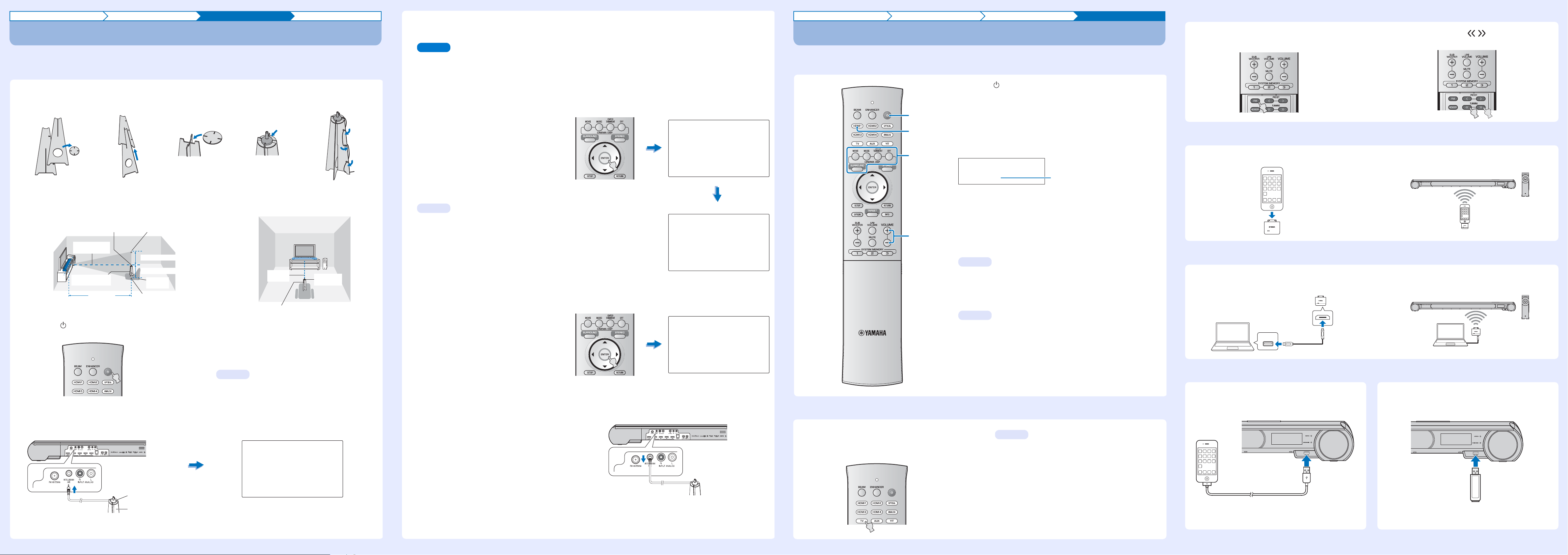
Place the IntelliBeam microphone at your normal listening position.
Assemble the cardboard microphone stand and place the IntelliBeam microphone on top of it horizontally as shown below.
Use the supplied cardboard microphone stand to place the IntelliBeam microphone at the same height as your ears would be when you
are seated.
Make sure that there are no obstacles between the IntelliBeam microphone and the walls in your listening room as these objects obstruct
the path of sound beams.
4.
Connect the IntelliBeam microphone to the INTELLIBEAM MIC jack on the rear of the unit.
2.
Press the key on the remote control.
The power of this unit turns on.
3.
Turn the TV on and switch the TV’s input to
display video content from this unit.
When this unit is connected to the HDMI input on the TV (as
shown in “Connecting a TV and a Blu-ray disc player” in this
Quick Reference Guide), switch the TV’s input to “HDMI1”.
You can select the language for the menu display.
Press and hold the SETUP key until the “OSD LANGUAGE”
menu appears. Press the S/Tkey to select the desired
language. Press the SETUP key again to exit the setup menu.
12345
Remove
Fit in
Fit in
Place horizontally
Run
through
IntelliBeam microphone Upper limit
Center height of
this unit
Within 1 m (3.3 ft)
Within 1 m (3.3 ft)
Listening
position
Cardboard
microphone stand
1.8 m (6.0 ft)
or more Lower limit
Center
line IntelliBeam
microphone
Cardboard microphone stand
yTip
AUTO SETUP
(PREPARATION & CHECK)
Please connect the MIC.
Please place the MIC at least
1.8m/6ft away from Sound Pro-
jector. The MIC should be set
at ear level when seated.
Measurement takes about 3min.
After [ENTER] is pressed,
please leave the room.
[ENTER]:Start [RETURN]:Cancel
IntelliBeam microphone (supplied)
Cardboard microphone stand (supplied)
5.
Make sure that your listening room is as quiet as possible.
For accurate measurement, turn off air conditioner or other devices that make noises.
Follow the instructions below and then leave the room. If you remain in the room, you may obstruct the beam, or the microphone may
pick up any sounds you make, possibly resulting in improper configuration of settings.
When leaving the room, bring this Quick Reference Guide with you. The AUTO SETUP procedure takes about 3 minutes. Wait outside
the room during the AUTO SETUP procedure.
To cancel the AUTO SETUP procedure after it is started, press the RETURN key on the remote control.
6.
Press the ENTER key to start the AUTO
SETUP procedure and then leave the room
within 10 seconds.
The screen automatically changes during the AUTO
SETUP procedure.
If the AUTO SETUP procedure is complete, this unit rings
the chimes and the results will be displayed on the TV.
If “ENVIRONMENT CHECK:Failure” is displayed, see
page 27 of the Owner’s Manual and run the measurement
process again.
• The results displayed depend on the position of the
unit.
• If you hear a buzzer sound and an error message
appears on the TV, look for a solution in “If an error
message is displayed” on page 27 of the Owner’s
Manual. Then press the RETURN key to run the
measurement process again.
7.
Press the ENTER key.
Measurement results are applied to this unit.
• You can save the several measurement results
pressing the SYSTEM MEMORY key (see page 28 of
the Owner's Manual).
8.
Remove the IntelliBeam microphone.
Keep the IntelliBeam microphone in a safe place.
The settings are automatically saved in the system
memory.
Note
Will begin in 10 sec.
Please leave the room
----------
AUTO SETUP START
[RETURN]:Cancel
(After 3 min.)
ENVIRONMENT CHECK: Success
BEAM MODE: 5Beam/Plus2
SHOW RESULT
MESUREMENT COMPLETE.
[ENTER]:Save set-up.
[RETURN]:Do not save set-up.
yTips
AUTO SETUP COMPLETE
Please remove the MIC
from Sound Projector
and the listening position.
Press [SYSTEM MEMORY] key
to save set-up in the memory.
Installation Connection Settings Playback
Playing back
Confirm that this unit and other audio/video devices are properly connected by playing a DVD or BD on the Blu-ray disc player. The following
explains the playback procedure when this unit, TV, and Blu-ray disc player are connected as shown in “Connecting a TV and a Blu-ray disc
player” in this Quick Reference Guide.
■Enjoying TV in surround sound
1.
Press the key to turn on this unit.
2.
Turn on your TV and Blu-ray disc player connected to this
unit.
3.
Press the HDMI1 key to select the Blu-ray disc player as the
input source.
4.
Switch the TV’s input to HDMI 1.
5.
Play back a DVD or BD on the Blu-ray disc player.
6.
Press the VOLUME (+/-) key to adjust the volume.
Use TV remote control to mute the sound from TV.
7.
Press the SURROUND key and then the CINEMA DSP keys
to set your sound preferences.
When this unit does not play back, check the following
• The connection between this unit and Blu-ray disc player.
• The audio output settings of Blu-ray disc player is set to digital sound output.
• The TV’s input is switched to this unit.
6
1
7
3
HDMI1
Input source name
yTip
yTips
1.
Select the desired TV channel.
2.
Press the TV key.
HDMI control function
You can use the TV remote control to operate this unit if your
TV supports the HDMI control function. See page 31 of the
Owner’s Manual.
yTip
■FM tuning (YSP-4300 only)
■Playing music stored on an iPod via YIT-W12TX
■Playing music stored on a computer via YIT-W12TX
■
Playing music stored on an iPod or USB device over a USB connection (YSP-4300 only)
For detailed operation, refer to the Owner’s Manual on the supplied CD-ROM.
1.
Press the FM key.
2.
Press the TUNING / key to specify the
frequency.
For details of YIT-W12TX, refer to “Safety and
Accessory Information” (separate booklet).
1.
Connect YIT-W12TX to the iPod.
2.
Start playback of music stored on the iPod.
For details of YIT-W12TX, refer to “Safety and
Accessory Information” (separate booklet).
1.
Connect YIT-W12TX to the computer via the
USB cable for YIT-W12TX.
2.
Play music stored on the computer.
USB
Connect the iPod to the USB jack on the front
of this unit using the USB cable supplied with
the iPod.
For more information on playing music stored on the iPod,
refer to “Playing music stored on an iPod or USB device over
a USB connection” in the Owner's manual.
Connect a USB device to the USB jack on the
front of this unit.
For more information on playing music stored on USB device,
refer to “Playing music stored on an iPod or USB device over
a USB connection” in the Owner's manual.

Other manuals for YSP-4300

5

This manual suits for next models

4

Other Yamaha Home Theater System manuals

Yamaha BRX-610 User manual

Yamaha

Yamaha BRX-610 User manual

Yamaha YHT-S300 User manual

Yamaha

Yamaha YHT-S300 User manual

Yamaha AV-S70 User manual

Yamaha

Yamaha AV-S70 User manual

Yamaha YHT-391 Instruction Manual

Yamaha

Yamaha YHT-391 Instruction Manual

Yamaha CinemaStation DVR-S150 User manual

Yamaha

Yamaha CinemaStation DVR-S150 User manual

Yamaha NS-PC8 User manual

Yamaha

Yamaha NS-PC8 User manual

Yamaha YHT-780BL User manual

Yamaha

Yamaha YHT-780BL User manual

Yamaha YHT-885BG User manual

Yamaha

Yamaha YHT-885BG User manual

Yamaha ATS-2030 User manual

Yamaha

Yamaha ATS-2030 User manual

Yamaha DVX-C310 User manual

Yamaha

Yamaha DVX-C310 User manual

Yamaha NS-C55 User manual

Yamaha

Yamaha NS-C55 User manual

Yamaha YHT-900 Assembly instructions

Yamaha

Yamaha YHT-900 Assembly instructions

Yamaha DVR-C310 User manual

Yamaha

Yamaha DVR-C310 User manual

Yamaha YHT-570 Instruction Manual

Yamaha

Yamaha YHT-570 Instruction Manual

Yamaha NS-A528 User manual

Yamaha

Yamaha NS-A528 User manual

Yamaha YHT-1840 User manual

Yamaha

Yamaha YHT-1840 User manual

Yamaha DVX-S200 User manual

Yamaha

Yamaha DVX-S200 User manual

Yamaha NS-PC8 User manual

Yamaha

Yamaha NS-PC8 User manual

Yamaha CinemaStation DVX-C300 User manual

Yamaha

Yamaha CinemaStation DVX-C300 User manual

Yamaha YHT-750 Assembly instructions

Yamaha

Yamaha YHT-750 Assembly instructions

Yamaha neoHD YMC-700 User manual

Yamaha

Yamaha neoHD YMC-700 User manual

Yamaha NS-P240 User manual

Yamaha

Yamaha NS-P240 User manual

Yamaha YHT-390BL User manual

Yamaha

Yamaha YHT-390BL User manual

Yamaha YHT-S300 User manual

Yamaha

Yamaha YHT-S300 User manual

Popular Home Theater System manuals by other brands

Sony HT-DDW860 Speakers Connection

Sony

Sony HT-DDW860 Speakers Connection

JVC TH-A25 instructions

JVC

JVC TH-A25 instructions

LG HB1100RE owner's manual

LG

LG HB1100RE owner's manual

Christie DW Series Brochure & specs

Christie

Christie DW Series Brochure & specs

Teufel System 6THX Select Technical specifications and operating manual

Teufel

Teufel System 6THX Select Technical specifications and operating manual

JVC TH-C5 Service manual

JVC

JVC TH-C5 Service manual

Elan HD series Homeowner's information

Elan

Elan HD series Homeowner's information

Sony BDV-E190 quick start guide

Sony

Sony BDV-E190 quick start guide

Coby DVD978 instruction manual

Coby

Coby DVD978 instruction manual

DK Digital AS-200 owner's manual

DK Digital

DK Digital AS-200 owner's manual

Hisense Laser Cinema PL1H Series Quick setup guide

Hisense

Hisense Laser Cinema PL1H Series Quick setup guide

Teufel Motiv 10 Technical description and operating instructions

Teufel

Teufel Motiv 10 Technical description and operating instructions

Atlantic Technology Pattern instruction manual

Atlantic Technology

Atlantic Technology Pattern instruction manual

Philips HTS3541 user guide

Philips

Philips HTS3541 user guide

Philips MCD712 quick start guide

Philips

Philips MCD712 quick start guide

JVC TH-S33 Service manual

JVC

JVC TH-S33 Service manual

Horizon Fitness Acustico HAV-H8700 operating instructions

Horizon Fitness

Horizon Fitness Acustico HAV-H8700 operating instructions

Sharp HT-SL50 Operation manual

Sharp

Sharp HT-SL50 Operation manual

manuals.online logo
manuals.online logoBrands
  • About & Mission
  • Contact us
  • Privacy Policy
  • Terms and Conditions

Copyright 2025 Manuals.Online. All Rights Reserved.