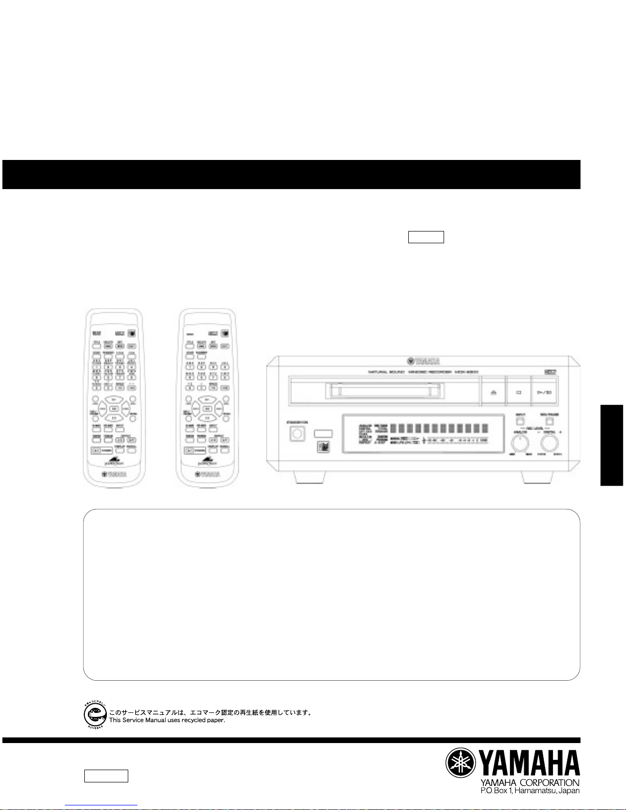
Yamaha MDX-E300 User manual

100806
SERVICE MANUAL
MDX-E300
IMPORTANT NOTICE
This manual has been provided for the use of authorized YAMAHA Retailers and their service personnel.
It has been assumed that basic service procedures inherant to the industry, and more specifically YAMAHA Products, are already known and understood by the users,
and have therefore not been restated.
WARNING: Failure to follow appropriate service and safety procedures when servicing this product may result in personal injury, destruction of expensive
components and failure of the product to perform as specified. For these reasons, we advise all YAMAHA product owners that all service required
should be performed by an authorized YAMAHA Retailer or the appointed service representative.
IMPORTANT: The presentation or sale of this manual to any individual or firm does not constitute authorization, certification or recognition of any applicable
technical capabilities, or establish a principle-agent relationship of any form.
The data provided is believed to be accurate and applicable to the unit(s) indicated on the cover. The research, engineering, and service departments of YAMAHA are
continually striving to improve YAMAHA products. Modifications are, therefore, inevitable and specifications are subject to change without notice or obligation to
retrofit. Should any discrepancy appear to exist, please contact the distributor's Service Division.
WARNING: Static discharges can destroy expensive components. Discharge any static electricity your body may have accumulated by grounding yourself to the
ground buss in the unit (heavy gauge black wires connect to this buss).
IMPORTANT: Turn the unit OFF during disassembly and parts replacement. Recheck all work before you apply power to the unit.
MINIDISC RECORDER
For the system operation of MDX-E300, please refer to Service Manual #100805 for the CRX-E300/NX-E300.
▼ J model ▼ R, G, B model
本機の「システム動作」については、CRX-E300/NX-E300のサービスマニュアル100805をご覧ください。
MDX-E300

MDX-E300
2
MDX-E300
■TO SERVICE PERSONNEL
1. Critical Components Information
Components having special characteristics are marked Z
and must be replaced with parts having specifications equal
to those originally installed.
2. Leakage Current Measurement (For 120V Models Only)
When service has been completed, it is imperative to verify
that all exposed conductive surfaces are properly insulated
from supply circuits.
●Meter impedance should be equivalent to 1500 ohm shunted
by 0.15µF.
●Leakage current must not exceed 0.5mA.
●Be sure to test for leakage with the AC plug in both
polarities.
AC LEAKAGE
TESTER OR
EQUIVALENT
EQUIPMENT
UNDER TEST
INSULATING
TABLE
WALL
OUTLET
WARNING: CHEMICAL CONTENT NOTICE!
The solder used in the production of this product contains LEAD. In addition, other electrical/electronic and/or
plastic (where applicable) components may also contain traces of chemicals found by the California Health and
Welfare Agency (and possibly other entities) to cause cancer and/or birth defects or other reproductive harm.
DO NOT PLACE SOLDER, ELECTRICAL/ELECTRONIC OR PLASTIC COMPONENTS IN YOUR MOUTH FOR
ANY REASON WHATSOEVER!
Avoid prolonged, unprotected contact between solder and your skin! When soldering, do not inhale solder fumes
or expose eyes to solder/flux vapor!
If you come in contact with solder or components located inside the enclosure of this product, wash your hands
before handling food.
THE MINI DISC RECORDER SHOULD NOT BE ADJUSTED OR REPAIRED BY ANYONE EXCEPT PROPERLY QUALIFIED
SERVICE PERSONNEL.
TROUBLESHOOTING /トラブルシューティング .....
36–45
IC DATA . . . . . . . . . . . . . . . . . . . . . . . . . . . . . . . .46–55
BLOCK DIAGRAM . . . . . . . . . . . . . . . . . . . . . . . . 56–57
TEST POINT WAVEFORMS . . . . . . . . . . . . . . . . . . . 58
PRINTED CIRCUIT BOARD . . . . . . . . . . . . . . . .59–62
MD VOLTAGES . . . . . . . . . . . . . . . . . . . . . . . . . . . . . 62
SCHEMATIC DIAGRAM . . . . . . . . . . . . . . . . . . .63–64
DISPLAY DATA . . . . . . . . . . . . . . . . . . . . . . . . . . . . . 65
PARTS LIST . . . . . . . . . . . . . . . . . . . . . . . . . . . . . 66–77
GREASE APPLICATION DIAGRAM . . . . . . . . . . . . 78
REMOTE CONTROL TRANSMITTER . . . . . . . . . . . 79
PARTS LIST FOR CARBON RESISTORS . . . . . . . 80
■ CONTENTS
TO SERVICE PERSONNEL . . . . . . . . . . . . . . . . . . 2–3
PREVENTION OF ELECTRO STATIC DISCHARGE . . . . . .
4
REAR PANELS . . . . . . . . . . . . . . . . . . . . . . . . . . . . . . 4
SPECIFICATIONS . . . . . . . . . . . . . . . . . . . . . . . . . . . . 5
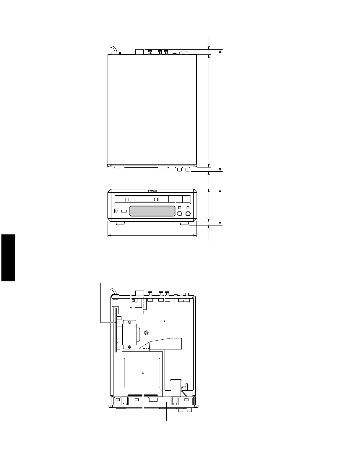
DIMENSIONS . . . . . . . . . . . . . . . . . . . . . . . . . . . . . . . . 6
INTERNAL VIEW . . . . . . . . . . . . . . . . . . . . . . . . . . . . . 6
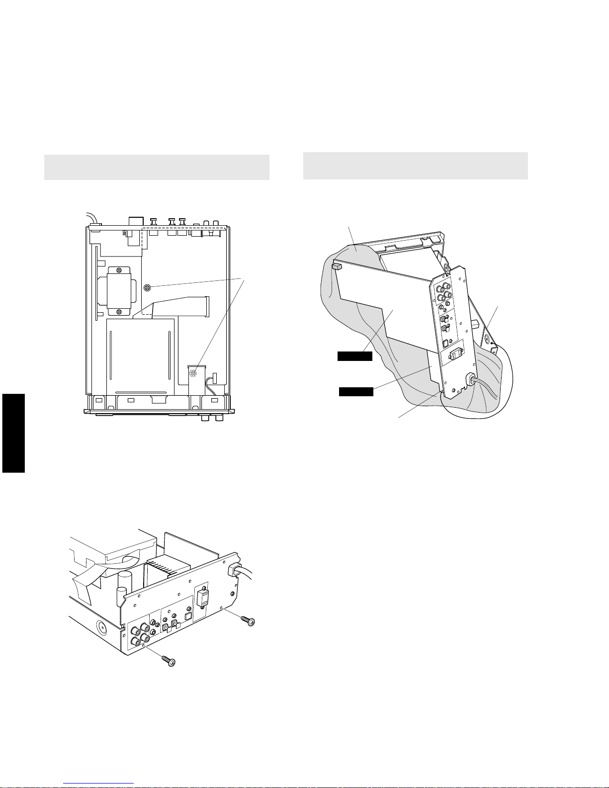
DISASSEMBLY PROCEDURES /分解手順 ...... 7–8
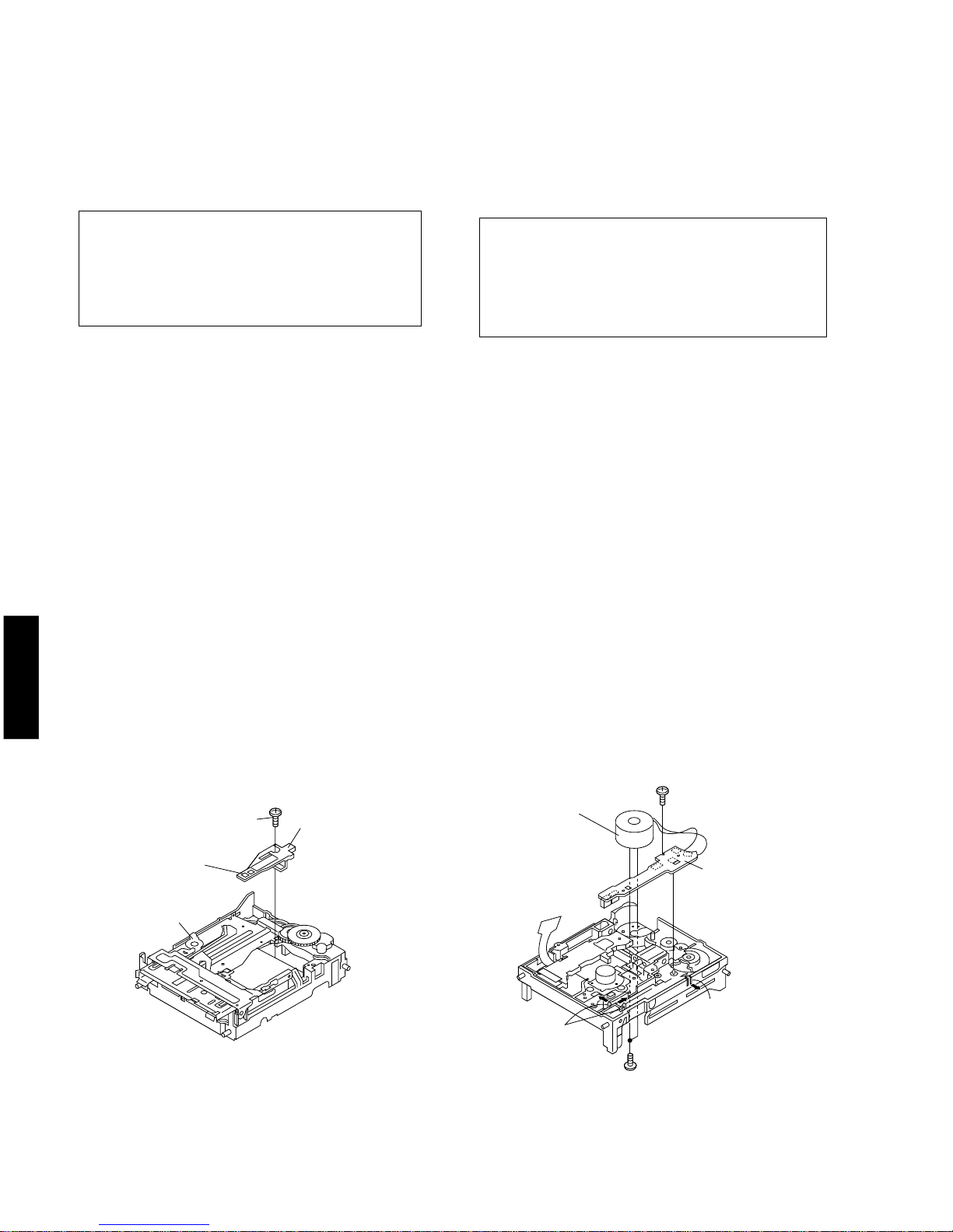
DISASSEMBLY OF MD RECORDER UNIT /
MDレコーダーユニットの分解 ................... 9–11
ADJUSTMENT & TEST MODE /
調整及びテストモード ........................ 12–29
SPECIAL TEST MODE /特殊テストモード ..... 30–31
ERROR DISPLAY /エラー表示 .............. 32–35

MDX-E300
MDX-E300
3
WARNING: Laser Safety
This product contains a laser beam component. This component may emit invisible, as well as visible radiation,
which may cause eye damage. To protect your eyes and skin from laser radiation, the following precautions must
be used during servicing of the unit.
1) When testing and/or repairing any component within the product, keep your eyes and skin more than 30 cm away from
the laser pick-up unit at all times. Do not stare at the laser beam at any time.
2) Do not attempt to readjust, disassemble or repair the laser pick-up, unless noted elsewhere in this manual.
3) CAUTION : Use of controls, adjustments or performance of procedures other than those specified herein may result in
hazardous radiation exposure.
Laser Emitting conditions:
1) When the Top Cover of the MD recorder unit is removed, and the “STANDBY/ON”SW is turned to the "ON" position,
the laser component will emit a beam for several seconds to detect if a disc is present. During this time (5-10 sec.) the
laser may radiate through the lens of the laser pick-up unit. Do not attempt any servicing during this period!
If no disc is detected, the laser will stop emitting the beam. When a disc is set, you will not be exposed to any laser
emissions.
2) The laser power level can be adjusted with the VR on the pick-up PWB. However, this level has been set by the factory
prior to shipping from the factory. Do not adjust this laser level control unless instruction is provided elsewhere in this
manual. Adjustment of this control can increase the laser emission level from the device.
VARO! : AVATTAESSA JA SUOJALUKITUS OHITETTAESSA OLET ALTTIINA NÄKYMÄTTÖMÄLLE
LASER-SÄTEILYLLE. ÄLÄ KATSO SÄTEESEEN.
VARNING! : OSYNLIG LASERSTRÅLNING NÄR DENNA DEL ÄR ÖPPNAD OCH SPÄRREN ÄR URKOPPLAD.
BETRAKTA EJ STRÅLEN.
Laser Diode Properties
Material : GaAlAs
Wavelength : 785 nm
Emission duration : Continuous
Pulse Durations and Max. Output at the lens of the Laser Pick Up Unit ;
Read mode : 0.6 mW (Continuous)
Write mode : Max 10 mW for 0.5s, Min. Cycle 1.5s
ANSI Class : Class 1
* This output is the value measured at a distance of about 200 mm from
the objective lens surface on the Optical Pick-up Block.
Magnetic head
Optical pick-up
➀
➁
R, G, B models
R, G, B models

MDX-E300
4
MDX-E300
■PREVENTION OF ELECTRO STATIC DISCHARGE
The laser diode in the MD recorder unit (optical pickup) may be damaged due to static electricity from clothes or the
human body. Use caution to prevent electrostatic damage when servicing or handling the laser diode.
1. Grounding for electrostatic damage prevention
1. Worktable grounding
Put a grounded conductive material (sheet) or iron sheet on the area where the optical pickup is placed.
2. Human body grounding
Use an anti-static wrist strap to discharge the static electricity from your body.
2. Handling of the optical pickup
Do not use a tester to check the laser diode in the optical pickup. The power supply in the tester will damage the
laser diode.
3. Handling Precautions for the MD recorder Unit (Optical Pickup)
1. Handle the MD recorder unit (optical pickup) gently, as it is an extremely high-precision assembly.
2. The flexible cable lines may break if an excessive force is applied to it. Use caution when handling the cable.
3. The semi-fixed resistor for laser power adjustment should not be adjusted. Do not turn the resistor.
1MΩ
Conductive material
(sheet) or steel sheet
Anti-static wrist strip
■REAR PANELS
▼ R model
▼ B model
▼ G model
▼ J model

MDX-E300
MDX-E300
5
■SPECIFICATIONS
Digital audio system
System/形式
MiniDisc digital audio system
Disc/ディスク
MiniDisc
Recording method/記録方式
Magnetic field variation overwrite
Reading method/再生読み取り方式
Non-contact optical pickup (using semiconductor laser)
Laser/レーザー
Semiconductor laser
Record/playback time/録音再生時間
Max. 80 min. (on stereo)
Max. 161 min. (on ATRAC3-LP2)
Max. 323 min. (on ATRAC3-LP4)
Revolutions /回転数
Approx. 400-900 rpm (CLV)
Error Correction/エラー訂正方式
ACIRC (Advanced Cross Interleave Reed-solomon Code)
Sampling frequency/サンプリング周波数
44.1 kHz (32 kHz and 48 kHz signals converted to 44.1 kHz
for recording)
Coding/コーディング
ATRAC (Adaptive TRansform Acoustic Coding)
Modulation system/変調方式
EFM (Eight-to-Fourteen Modulation)
Number of channels/チャンネル数
2 (stereo) or 1 (mono, for extended recording)
Frequency Response/周波数特性
5 - 20,000 Hz ±0.5 dB
Signal-to-Noise Ratio/SN比
More than 99 dB during playback
Wow and Flutter/ワウフラッター
Below measurable limit
Inputs
LINE IN (REC) /ライン入力
Type: pin jack
Input impedance: greater than 50 k-ohms
Standard input level: 300 mV
DIGITAL IN (OPTICAL) 1/2 /デジタル入力(光)1/2
Type: square optical connector jack
Outputs
LINE OUT (PLAY) /ライン出力
Type: pin jack
Standard output level: 2.0 ±0.5 Vrms
DIGITAL OUT (OPTICAL) /デジタル出力(光)
Type: square optical connector jack
GENERAL
Power Supplies/電源
G, B models 230 V, 50 Hz
R model 110/120/220/240 V, 50/60 Hz
J model 100 V, 50/60 Hz
Power Consumption/消費電力
R, G, B models 12W
J model 11W
Dimensions (W x H x D)/外形寸法(幅x高さx奥行)
217 x 88 x 297 mm (8-9/16" x 3-7/16" x 11-11/16")
Weight/重量
2.6 kg (5 lbs. 11 oz.)
Finish/仕上げ
Silver color B, G, J models
Gold color R, G models
Accessories/付属品
Remote Control.... 1
Audio Pin Cable... 2
Optical Cable... 1
Batteries (AA, R6, UM-3).... 2
Specifications subject to change without notice.
B : British model
G : European model
R : General model
J : Japanese model

MDX-E300
6
MDX-E300
■INTERNAL VIEW
qMAIN (3) P.C.B.
wMAIN (4) P.C.B.
eMAIN (1) P.C.B.
rMD RECORDER UNIT
tMAIN (2) P.C.B.
e
r t
wq
■DIMENSIONS
Unit : mm (inch)
217 (8-9/16")
8
(5/16")
80 (3-1/8")
88 (3-4/16")
12
(1/2")
10
(3/8")
275 (10-13/16")
297 (11-11/16")

MDX-E300
MDX-E300
7
CB602
CB1
CB6
■DISASSEMBLY PROCEDURES/分解手順
1. Removal of Top Cover
Remove 4 screws ( q ) and 4 screw
( w
)
in Fig. 1.
2. Removal of Front Panel
a. Remove 2 connectors (CB6, CB602) in Fig. 2.
b. Remove 2 screws
( e )
and 2 screws
( r )
in Fig. 1
.
c. Detach the 2 hooks in Fig. 1 and then pull the Front
Panel forward.
3. Removal of MD Recorder Unit
a. Remove 1 connector (CB1) in Fig. 2.
b. Remove 4 screws ( t) in Fig. 1.
c. Remove the MD Recorder Unit.
1. トップカバーの外し方
qw
2.フロントパネルの外し方
er
3. MDレコーダーユニットの外し方
t
Remove parts in disassembly order as numbered. (番号順に取り外しを行ってください。)
Fig. 1
Fig. 2
q
q
w
w
w
t
t
e
e
r
Hook
Hook
Top Cover
Front Panel
MD Recorder Unit
フック
フック
MDレコーダーユニット
フロントパネル
トップカバー

MDX-E300
8
MDX-E300
●サービスポジション
y
u
●Service Position
a. Remove 2 screws (y) in Fig. 3.
b. Remove 2 screws (u) in Fig. 4.
c. Remove the Main (1) P.C.B. from the chassis.
d. Place the Main (1) P.C.B. and Main (4) P.C.B. as shown
in Fig. 5 for servicing.
Fig. 3
Fig. 4
Fig. 5
MAIN (1)
MAIN (4)
y
u
u
Cloth
P.C.B.チェックをする場合には
Main(4)P.C.B.の ST1 をリード線等でシャーシに接続してく
ださい。
When checking the P.C.B.:
Be sure to connect the ST1 of the Main (4) P.C.B. to the
chassis with a jumper wire or the like.
シャーシ
メイン(1)
メイン(4)
布
ST1
Chassis

MDX-E300
MDX-E300
9
Removal of MD Main P.C.B. and MD Mechanism (Fig. 6)
1. Remove 3 screws (K1) and then remove the Top
Cover.
2. Remove 2 screws (K2) and then remove the Bottom
Cover.
3. Disconnect 3 flat connecting cables (K3).
4. Disconnect the flexible P.C.B. for the optical pickup
(K4).
5. Disconnect a connector (K5).
6. Remove 2 screws (K6) and then remove the MD
Main P.C.B.
7. Remove the spring (K7).
8. Remove 1 screw (K8) and then remove the Side
Cover.
9. Remove 4 cushions (K9) from the bosses of the MD
Mechanism.
Remove the MD Recorder unit according to Steps 1 and 3
of the disassembly procedure.
■DISASSEMBLY OF MD RECORDER UNIT/MDレコーダーユニットの分解
●MDメイン基板・MDメカニズムの外し方(Fig.6参照)
分解手順1と3に従ってMDレコーダユニットを取り外し
てください。
Fig. 6
(K3)x2
(K2)x1
ø2x 2mm
(K1)x1
ø2x 3mm
(K1)x1
ø2x 3mm
(K1)x1
ø2x 3mm
(K3)x1
(K5)x1
(K2)x1
ø2x 3mm
(K6)x2
ø1.7x 3mm
(K4)x1
(K8)x1
ø2x 3mm
(K7)x1
Top Cover
MD Mechanism
Cushion
Cushion
Side Cover
MD Main P.C.B.
Flexible P.C.B. for optical pickup (*1)
Bottom Cover
(*1) After pulling off the
flexible P.C.B. for the optical
pickup from the connector,
cover its end with aluminum
foil or the like which is
electrically conductive so as
to prevent the optical pickup
from being
damaged by static electricity.
Pull
Pull
Spring
(K9)x2
(K9)x2
Boss
Boss
(*1)光ピックアップ用フレキ
基板をコネクタから引き抜い
た後は、静電気による光ピッ
クアップの破壊を防止するた
めに、フレキ基板の先端を導
電性のあるアルミ箔等で包ん
でください。
引く
引く
シールドケース(ボトム)
光ピックアップ用フレキ基板(*1)
MDメイン基板
クッション
クッション
シールドケース(サイド)
スプリング
ボス
ボ
ス
MDメカニズム
シールドケース(トップ)

MDX-E300
10
MDX-E300
Removal of Magnetic Head (Fig. 7)
•Once the magnetic head is removed, it will be neces-
sary to perform “Confirmation of magnetic head
installation Position”. (See page 26.)
Remove screw (A1).
Caution
a. When removing the magnetic head, hold its base and
do not touch the magnetic head itself or the leaf
spring.
b. Place the magnetic head upside down.
c. Use special care so as not to cause any damage to
the magnetic head when installing it.
Fig. 7
(A1)x1
ø1.7x 5mm
Magnetic Head
Leaf Spring
MD Mechanism
磁気ヘッド
MDメカニズム
リーフバネ
Fig. 8
Removal of MD Loading P.C.B./Loading Motor (Fig. 8)
1. Remove 1 screw (B1).
2. Remove 3 hooks (B2) and then remove the MD
Loading P.C.B.
3. Remove 2 screws (B3) and then remove the Loading
Motor.
(B3)x2
ø1.7x 3mm
(B1)x1
ø1.7x 6mm
(B2)x2
(B2)x1
MD Loading P.C.B.
Loading Motor
ローディングモーター
MDローディング基板
●磁気ヘッドの外し方(Fig.7参照)
・ 磁気ヘッドを外した場合、『磁気ヘッドの取付位置』
の確認が必要です。(27ページ参照)
注意
●MDローディング基板/ローディングモータの外し方
(Fig.8参照)

MDX-E300
MDX-E300
11
Removal of Sled Motor/Optical Pickup Head (Fig. 9)
•Once the MD mechanism switch P.C.B. is removed, it
will be necessary to perform “Adjustment of Lead-in
Switch Position”. (See page 26.)
•Once the optical pickup head is removed, it will be
necessary to perform “Confirmation of magnetic head
installation Position”. (See page 26.)
1. Remove 3 screws (C1) and then remove the sled
motor.
2. Remove the Optical Pickup Head.
Caution
Use care so as not to cause any damage to the gear.
(A damaged gear will cause abnormal noise to occur
while searching.)
(C1)x2
ø1.4x 4.5mm
(C1)x1
ø1.4x 5mm
Sled Motor
MD Mechanism P.C.B.
Optical Pickup Head
光ピックアップ
スレッドモーター
MDメカニズムスイッチ基板
Fig. 9
Removal of Spindle Motor (Fig. 10)
•Once the spindle motor is removed, it will be neces-
sary to perform “Pickup Rating”. (See page 28.)
Remove 3 screws (D1) and then remove the Spindle
Motor.
Caution
a. Be careful not to scratch the gear.
(Scratched gear will produce noises during searching.)
b. As the turn-table is magnetized, keep foreign objects
from being attracted.
(D1)x3
ø1.4x 3mm
Spindle Motor
スピンドルモータ
ー
Fig. 10
●スレッドモータ/光ピックアップの外し方(Fig.9参照)
・ MDメカニズムスイッチ基板を外すと、『リードインス
イッチ位置』の調整が必要です。(27ページ参照)
・ 光ピックアップを外すと、『磁気ヘッド位置』の確認が
必要です。(27ページ参照)
注意)
●スピンドルモータの外し方(Fig.10参照)
・ スピンドルモータを外すと、『グレーティング調整』が
必要です。(29ページ参照)
注意
a. ギヤを傷つけないように注意してください。
(ギヤが傷つくと、サーチ時異音が発生する為)
b. ターンテーブルは磁化されていますので、異物吸着しない
ようにしてください。

MDX-E300
12
MDX-E300
●Extension cable
(see connection diagram on page 28.)
High reflecting disc TDYS1 (SONY) [for reproduction] (P/No. TX945850)
Low reflecting disc Commercially available mini disc for recording
Low reflecting disc MMD-318 [for pre-adjustment] (P/No. AAX04890)
––––––––Clear disc for checking the head (P/No. AAX18050)
Type Test disc
1. Extension P.C.B. for servicing AAX16660
2. 2-pin extension connector for servicing AAX16620
3. 6-pin flat cable for servicing AAX16640
4. 5-pin flat cable for servicing TX946190
5. 28-pin flat cable for servicing TX946220
Type Part No.
■ADJUSTMENT & TEST MODE
Preparation before Adjustment
●Test disc
Servicing Procedure
Perform adjustment and setup in the TEST mode. Specific adjustments and procedures vary depend-
ing on the type of servicing performed.
Type of servicing
PICKUP replacement
Magnetic head replacement
Mechanical unit replacement
(including PICKUP)
MD main PCB replacement
MD microprocessor (IC1401)
replacement
MD LSI (IC1201) replacement
RF IC (IC101) replacement
EEPROM IC (IC1402) replacement
TEMP standard
setting
TEMP
–
–
–
q
–
–
q
q
EEPROM setting
value confirmation
EEPROM SET
q
–
q
w
q
_
w
w
AUTO preliminary
adjustment
AUT YOBI
w
–
w
e
–
q
e
e
AUTO
adjustment
AUTO AJST
e
–
e
r
_
w
r
r
AUTO AFB
adjustment
AUT AFB
r
–
r
t
_
e
t
t
EEPROM adjustment
value entry (*1)
TEST mode cancel
t
–
t
y
w
r
y
y
Operation confirmation
(With AUTO main adjustment done in advance)
TEST-PLAY
y
–
y
u
e
t
u
u
TEST-REC
u
q
u
i
r
y
i
i
Required item
Numbers in the table, e.g., q, w, e, indicate the order in which required items should be performed.
"–" means that item needs not be performed.
(*1): The result of EEPROM entry is displayed at the end of the TEST mode.
OK_EEPROM: Both "setting value" and "preliminary adjustment completed" have been entered properly.
WR_EEPROM: The "setting value" has been entered properly but not "preliminary adjustment completed".
Perform preliminary adjustment properly and then enter "preliminary adjustment completed".
NG_EEPROM: The "setting value" has not been entered.
Check the MD microprocessor and EEPROM for connection.

MDX-E300
MDX-E300
13
■ 調整及びテストモード
修理内容により、テストモードでの調整及び設定を実施してください。
必要実施項目
修理内容
TEMP
基準設定
TEMP
EEPROM
設定値確認
EEPROMSET
AUTO-
YOBI調整
AUTYOBI
AUTO-
本調整
AUTOAJST
AUTO-
AFB調整
AUTAFB
EEPROM調整
値書込み(*1)
テストモードの解除
動作確認
(予めAUTO本調整実施後)
TEST-PLAY TEST-REC
準備するもの
●テストディスク ●延長ケーブル(接続図29ページ参照)
1. 高反射ディスク TDYS1(SONY)[再生用] TX945850
2. 低反射ディスク 市販の録音用ミニディスク −−−−−−
3. 低反射ディスク MMD-318[予備調整用] AAX04890
4. −−−−−−− ヘッド確認用透明ディスク AAX18050
種類 テストディスク 部品NO.
1. サービス用延長基板 AAX16660
2. サービス用2ピン延長コネクタ AAX16620
3. サービス用6ピンフラットケーブル AAX16640
4. サービス用5ピンフラットケーブル TX946190
5. サービス用28ピンフラットケーブル TX946220
種類 部品NO.
サービス手順
(*1)

MDX-E300
14
MDX-E300
3. How to cancel test mode (Entry of EEPROM adjustment value)
1) Be sure to perform AUTO preliminary adjustment, AUTO adjustment and AUTO AFB adjustment.
( “COMPLETE”is displayed.)
2) After completing above ajustments, press the REC/PAUSE button (REMOCON). (Entry to EEPROM initiates then.)
The TEST mode is completed. ( “Test End”is displayed.)
3) Press the “v”button to take out the disc.
4) Turn off the power.
2. How to set to each mode
Every time the DISPLAY (forward) or EDIT (reverse) button on the remote control unit is pressed, the mode changes.
(For operation of each mode, refer to the section describing each mode.)
Since this mode is not required for servic-
ing , proceed to another mode promptly.
*
AUTO_AJST (AUTO adjustment)
@
AUT_AFB (AUTO AFB adjustment)
@
RST_YOBI (RESULT preparation)
@
RESULT (RESULT)
@
MNU_YOBI (MANUAL preliminary adjustment)
@
MNU_AJST (MANUAL adjustment)
@
EEPROM_SET (EEPROM setting)
@
AUT_YOBI (AUTO preliminary adjustment)
@
TEST MODE
1. How to enter the test mode
1) Press the “STANDBY/ON”button while pressing the “a”button and the “INPUT”button and then release your
hingers from those buttons.
“EJECT”is displayed.
2) Load either a disc for reproduction or a disc for recording.
“AUTO AJST”is displayed.

MDX-E300
MDX-E300
15
2.各モードの入り方
3.テストモードの解除(EEPROM調整値書き込み)
Test End
“v”
AUTO–AJST
AUT–AFB
RST–YOBI
RESULT
MNU–YOBI
MNU–AJST
EEPROM–SET
AUT–YOBI
テストモード
1.テストモードの入り方
“a”“”“”

MDX-E300
16
MDX-E300
●Confirmation of pick-up laser power
Recording and reproduction can be checked by using the
laser power meter. However it should be used for check-
ing only because there is variation in its measurement.
When the measured value is excessively deviated from
the reference value, replace the pick-up.
Reference value (measured at room temperature of
25 °C)
During reproduction (ppw) : 0.72 ±0.1 mW
During recording : 5.5 ±0.5 mW
Note : Be very careful when using the laser power meter.
The laser beam would cause damage to your eye if
exposed to it directly.
●TEMP (temperature standard) setting
(Make this setting quickly when the room tempera-
ture is within the range of 21 ˚C to 29 ˚C and the
P.C.B. is cold.)
(1) Set to the TEMP setting mode menu.
[ TEMP ❍ ❍ ◆ ◆ ]
❍ ❍ : Temperature measured value
◆ ◆ : Temperature setting value
(2) Make temperature correction based on the ambient
temperature and according to the following table.
Example : When the temperature measured value is 7AH
and the ambient temperature is 22 ˚C:
7A
H
(measured value) - 01
H
(correction value) = 79
H
(setting value)
* If the temperature measured value deflects between two val-
ues, use the smaller value (If 7AHand 79Hin the above ex-
ample, use 79H.)
(3) Using the jog dial, match the value obtained in Step
(2) with the temperature setting value.
Example : When the temperature measured value is 7AH
and the ambient temperature is 22 ˚C:
[ TEMP 7A 79 ]
Ambient temperature Correction value
+ 21.0 ˚C ~ + 23.2 ˚C–1H
+ 23.3 ˚C ~ + 26.8 ˚C±0H
+ 26.9 ˚C ~ + 30.7 ˚C+ 1H
Check procedure Mode Check item Judgement
Possible cause and check content
(Pin 3 of IC1401)
qPlayback power output “ppw”DC 0.2V OK (Move on to check w.) –
DC 1.5V NG Perform *1.
wRecording power output “rpw”DC 1.8V OK (End of checking.) –
Less than DC1.5V NG Perform *2.
“rpw”not achieved. –NG Perform *1.
*1: Poor soldering of the line at Pin 100 of IC1401.
Check the line of Pin 93 of IC1401 for short and poor soldering. (Check all the way to the SW P.C.B.)
*2: Check the line of Pin 3 of IC1401 for poor soldering and short with other patterns.
Check the pick-up laser for breakage.
Temperature setting value
1. EJECT mode
Step Setting method Remark Display
1
2
3
4
5
6
7
8
EJECT status in the TEST mode
Press the INPUT button (REMOCON).
Press the TITLE edit button (REMOCON).
Press the CHARA. button (REMOCON).
Press the DISPLAY button (REMOCON).
Press the DELETE/CANCEL button (REMOCON).
EJECT menu (No disc is loaded.)
Reproduction power output status
Recording power output status
Since this mode is not required for servicing , proceed to another mode promptly.
To TEMP setting
(Refer to TEMP setting)
To CONTROL1 setting
To CONTROL2 setting
EJECT menu
[ _ _ EJECT _ _ _ ]
[ ppw _ _ _ _ _ _ _ ]
[ rpw _ _ _ _ _ _ _ ]
[ xpw _ _ _ _ _ _ _ ]
[ TEMP _❍ ❍ _◆ ◆]
[ CONTROL _ 08 ]
[ CONTROL2 _ 02 ]
[ _ _ EJECT _ _ _ ]
(Jog dial)
Details of Test Mode

MDX-E300
MDX-E300
17
ステップNO. 設定方法 備 考 表 示
1.EJECTモード
●ピックアップレーザパワーの確認
テストモード詳細
チェック手順
モード チェック項目 判定 考えられる原因とチェック内容
IC1401の3番ピン
① 再生パワー出力『ppw』 DC0.2V OK(②チェックへ) −
DC1.5V NG *1を実施。
② 記録パワー出力『rpw』 DC1.8V OK(チェック終了) −
DC1.5V未満 NG *2を実施
『rpw』にならない − NG *1を実施。
●TEMP(温度基準)設定
(室温21℃〜29℃内で、基板が熱を持っていない状態にて素早
く行ってください。)
周囲温度 補正値
(ジョグダイアル)

MDX-E300
18
MDX-E300
3. AUTO adjustment mode Disc in use: TDYS1 (SONY) [for reproduction] or commercially available
mini disc for recording
Step Setting method Remark Display
1
2
3
4
5
6
Set the TEST mode.
Load a disc.
Press the SET/ENTER button
(REMOCON) once.
Adjusted values are output.
Adjustment is completed.
When adjustment is OK, press the
SET/ENTER button (REMOCON).
Press the INPUT button.
Press the DELETE/CANCEL button (REMOCON).
When adjustment is NG, press the
DELETE/CANCEL button (REMOCON).
No disc is loaded.
AUTO adjustment menu
Automatic adjustment is started after sliding to the innermost
track.
“*** ”changes in the following order when a high reflecting disc
(disc for reproduction) is used.
PEG -> HAG
“*** ”changes in the following order when a low reflecting disc
(disc for recording) is used.
PEG -> LAg -> GCG -> GEG -> LAG
Proceed to Step 4 when adjustment is OK.
Proceed to Step 6 when adjustment is NG.
Continuous reproduction (bit section) (Address + C1 error display)
Continuous reproduction (group section) (Address + C1 error display)
Continuous reproduction (group section) (Address + ADIP error display)
Display returns to the AUTO adjustment menu display.
There is an abnormality at the adjusted point such as PEG.
Refer to “Troubleshooting”. (page 36)
[ EJECT ]
[ LOADING ]
[ AUTO _ AJST _ ]
[ *** : _ _ _ _ _ _ ]
[ _ COMPLETE _ ]
[ Can't _ ADJ. ]
[ sXXXX cYYYY ]
[ aXXXX cYYYY ]
[ aXXXX aYYYY ]
[ AUTO _ AJST _ ]
[ Can't _ ADJ. ]
Note) *** : Adjustment name, XXXX: Address, YYYY: Measured value
2. AUTO preliminary adjustment mode Disc in use: MMD-318 [for pre-adjustment]
Step Setting method Remark Display
1
2
3
4
5
6
Set the Test mode.
Load a disc.
Press the EDIT button (REMOCON) once.
Press the SET/ENTER button
(REMOCON) once.
Adjusted values are output.
Adjustment is completed.
When adjustment is OK, press the
DELETE/CANCEL button (REMOCON).
When adjustment is NG, press the
DELETE/CANCEL button (REMOCON).
No disc is loaded.
Auto adjustment menu
Auto preliminary adjustment menu
Auto preliminary adjustment is started after sliding to the
innermost track.
“*** ”changes in the following order during automatic
adjustment.
HAo -> ................. -> TCO
Proceed to Step 5 when adjustment is OK.
Proceed to Step 6 when adjustment is NG.
The display returns to the AUTO preliminary adjustment menu.
There is an abnormality at the adjusted point such as HAo.
Refer to “Troubleshooting”. (page 36)
[ EJECT ]
[ LOADING ]
[ AUTO _ AJST _ ]
[ _ AUT _ YOBI _ ]
[ *** : _ _ _ _ _ _ ]
[ _ COMPLETE _ ]
[ Can't _ ADJ. ]
[ _ AUT _ YOBI _ ]
[ Can't _ ADJ. ]
4. AUTO AFB adjustment mode Disc in use: Commercially available mini disc for recording
Step Setting method Remark Display
1
2
3
4
5
Set the Test mode.
Load a disc.
Press the DISPLAY button (REMOCON) once.
Press the SET/ENTER button (REMOCON) once.
Press the DELETE/CANCEL button (REMOCON).
No disc is loaded.
Auto adjustment menu
Auto AFB adjustment menu
Auto AFB adjustment is started.
Adjusted values are output.
The display returns to the AUTO AFB adjustment menu.
[ EJECT ]
[ LOADING ]
[ AUTO _ AJST _ ]
[ _ AUT _ AFB _ _ ]
[ FAB YY _ ZZZZ ]
[ YY _ ZZZZ _ _ _ ]
[ _ AUT _ AFB _ _ ]
Note) YY, ZZZZ: Measured value

MDX-E300
MDX-E300
19
2.AUTO予備調整モード 使用するディスク:MMD-318[予備調整用]
ステップNO. 設定方法 備 考 表 示
3.AUTO調整モード 使用するディスク:TDYS1(SONY)[再生用]または市販の録音用ミニディスク
ステップNO. 設定方法 備 考 表 示
4.AUTOAFB調整モード 使用するディスク:市販の録音用ミニディスク
ステップNO. 設定方法 備 考 表 示

MDX-E300
20
MDX-E300
EEPROM SETTING MODE TRANSITION DIAGRAM
Note) To return to the SUB MENU or MAIN MENU display of the test mode, press the DELETE/CANCEL button.
5. EEPROM setting mode Disc in use: Commercially available mini disc for recording
(used to confirm/adjust setting values)
1) Start the TEST mode.
2) Load the disc.
[AUTO AJST]
3) Press the DISPLAY button (REMOCON) 6 times.
[EEPROM SET]
4) Execute the procedure to have “EEPROM setting mode transition diagram”displayed and adjust
the jog dial so that the same setting values as those in “EEPROM contents list”are obtained.
(Refer to p.16 for TEMP setting.)
5) Press the REC/PAUSE button (REMOCON) to cancel the TEST mode.
(Entry into EEPROM can be started here.)
6) Set to the TEST mode again and perform AUTO preliminary adjustment, AUTO adjustment and
AUTO AFB adjustment.
Other manuals for MDX-E300
2
Table of contents
Other Yamaha Mini Disc Recorder manuals

Yamaha
Yamaha MDX-E300 User manual

Yamaha
Yamaha MDX-E100 User manual

Yamaha
Yamaha MDX-793 User manual

Yamaha
Yamaha MDX-596 User manual

Yamaha
Yamaha MD4 Instruction Manual

Yamaha
Yamaha MD8 User manual

Yamaha
Yamaha MDX-9 User manual

Yamaha
Yamaha MDX-E100 User manual

Yamaha
Yamaha MDX-E300 User manual

Yamaha
Yamaha MDX-596 User manual