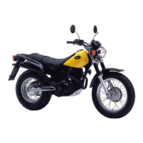
Yamaha TW125 2003 Manual


FOREWORD
This Supplementary Service Manual has been prepared to introduce new service and data for the
TW125 2003. For complete service information procedures it is necessary to use this Supplementary
Service Manual together with the following manual.
TW125 SERVICE MANUAL: 5EK1-AE1
TW125 SUPPLEMENTARY SERVICE MANUAL : 5EK1-AE2
TW125 2003
SUPPLEMENTARY
SERVICE MANUAL
!2002 by Yamaha Motor Co., Ltd.
First Edition, October 2002
Any reproduction or unauthorized use
without the written permission of
Yamaha Motor Co., Ltd. is expressly
prohibited.

NOTE:
WARNING
CAUTION:
EB001000
NOTICE
This manual was produced by the Yamaha Motor Company primarily for use by Yamaha dealers and
their qualified mechanics. It is not possible to include all the knowledge of a mechanic in one manual,
so it is assumed that anyone who uses this book to perform maintenance and repairs on Yamaha
motorcycle has a basic understanding of the mechanical ideas and the procedures of motorcycle
repair. Repairs attempted by anyone without this knowledge are likely to render the motorcycle unsafe
and unfit for use.
Yamaha Motor Company, Ltd. is continually striving to improve all its models. Modifications and
significant changes in specifications or procedures will be forwarded to all authorized Yamaha dealers
and will appear in future editions of this manual where applicable.
Designs and specifications are subject to change without notice.
EAS00004
IMPORTANT INFORMATION
Particularly important information is distinguished in this manual by the following notations.
The Safety Alert Symbol means ATTENTION! BECOME ALERT! YOUR
SAFETY IS INVOLVED!
Failure to follow WARNING instructions could result in severe injury or death to
the motorcycle operator, a bystander or a person inspecting or repairing the
motorcycle.
A CAUTION indicates special precautions that must be taken to avoid damage
to the motorcycle.
NOTE: A NOTE provides key information to make procedures easier or clearer.

1
2
5
7
6
43
8
EAS00007
HOW TO USE THIS MANUAL
This manual is intended as a handy, easy-to-read reference book for the mechanic. Comprehensive
explanations of all installation, removal, disassembly, assembly, repair and inspection procedures are
laid out with the individual steps in sequential order.
1The manual is divided into chapters. An abbreviation and symbol in the upper right corner of each
page indicate the current chapter. Refer to “SYMBOLS” on the following page.
2Each chapter is divided into sections. The current section title is shown at the top of each page,
except in Chapter 3 (“Periodic Inspections and Adjustments”), where the sub-section title(-s) appear.
(In Chapter 3, “Periodic Inspections and Adjustments”, the sub-section title appears at the top of each
page, instead of the section title.)
3Sub-section titles appear in smaller print than the section title.
4To help identify parts and clarify procedure steps, there are exploded diagrams at the start of each
removal and disassembly section.
5Numbers are given in the order of the jobs in the exploded diagram. A circled number indicates a
disassembly step.
6Symbols indicate parts to be lubricated or replaced (see “SYMBOLS”).
7A job instruction chart accompanies the exploded diagram, providing the order of jobs, names of
parts, notes in jobs, etc.
8Jobs requiring more information (such as special tools and technical data) are described sequen-
tially.

21
1
3
5
7
9
2
4
8
6
23 24
2220
18 1917
15
1413
11 12
10
GEN
INFO SPEC
ENG
CARB
ELEC
CHAS
CHK
ADJ
TRBL
SHTG
16
EAS00009
SYMBOLS
The following symbols are not relevant to every
vehicle.
Symbols 1to 8indicate the subject of each
chapter.
1General information
2Specifications
3Periodic checks and adjustments
4Engine
5Carburetor(-s)
6Chassis
7Electrical system
8Troubleshooting
Symbols 9to 16 indicate the following.
9Serviceable with engine mounted
10 Filling fluid
11 Lubricant
12 Special tool
13 Tightening torque
14 Wear limit, clearance
15 Engine speed
16 Electrical data
Symbols 17 to 22 in the exploded diagrams indi-
cate the types of lubricants and lubrication
points.
17 Engine oil
18 Gear oil
19 Molybdenum disulfide oil
20 Wheel bearing grease
21 Lithium soap base grease
22 Molybdenum disulfide grease
Symbols 23 to 24 in the exploded diagrams indi-
cate the following:
23 Apply locking agent (LOCTITE")
24 Replace the part

CONTENTS
SPECIFICATIONS
GENERAL SPECIFICATIONS 1. . . . . . . . . . . . . . . . . . . . . . . . . . . . . . . . . . .
CHASSIS SPECIFICATIONS 1. . . . . . . . . . . . . . . . . . . . . . . . . . . . . . . . . . . .
ELECTRICAL SPECIFICATIONS 2. . . . . . . . . . . . . . . . . . . . . . . . . . . . . . . .
CABLE ROUTING 3. . . . . . . . . . . . . . . . . . . . . . . . . . . . . . . . . . . . . . . . . . . . .
ELECTRICAL
CHECKING THE SWITCHES 13. . . . . . . . . . . . . . . . . . . . . . . . . . . . . . . . . . . .
LIGHTING SYSTEM 14. . . . . . . . . . . . . . . . . . . . . . . . . . . . . . . . . . . . . . . . . . . .
CIRCUIT DIAGRAM 14. . . . . . . . . . . . . . . . . . . . . . . . . . . . . . . . . . . . . . . . .
TROUBLESHOOTING 15. . . . . . . . . . . . . . . . . . . . . . . . . . . . . . . . . . . . . . .
TROUBLESHOOTING
FAULTY LIGHTING SYSTEM 17. . . . . . . . . . . . . . . . . . . . . . . . . . . . . . . . . . . .
HEADLIGHT DOES NOT COME ON 17. . . . . . . . . . . . . . . . . . . . . . . . . .
HEADLIGHT BULB BURNT OUT 17. . . . . . . . . . . . . . . . . . . . . . . . . . . . .
TW125 2003 WIRING DIAGRAM


–1–
GENERAL SPECIFICATIONS/CHASSIS SPECIFICATIONS SPEC
SPECIFICATIONS
GENERAL SPECIFICATIONS
Item Standard Limit
Model code 5RS3, 5RS4 !!!
CHASSIS SPECIFICATIONS
Item Standard Limit
Frame
Frame type
Caster angle
Trail
Diamond
25"83’
93 mm
!!!
!!!
!!!
Tire pressure (cold tire)
Maximum load-except motorcycle
Loading condition A*
front
rear
Loading condition B*
front
rear
Off road riding
front
rear
High speed riding
front
rear
180 kg
0 !90 kg
150 kPa (1.5 kg/cm2, 1.5 bar)
90 !180 kg
150 kPa (1.5 kg/cm2, 1.5 bar)
175 kPa (1.75 kg/cm2, 1.75 bar)
125 kPa (1.25 kg/cm2, 1.25 bar)
150 kPa (1.5 kg/cm2, 1.5 bar)
175 kPa (1.75 kg/cm2, 1.75 bar)
!!!
!!!
!!!
!!!
!!!
!!!
!!!
!!!
!!!
!!!
!!!
*Load is the total weight of cargo, rider, passenger, and accessories.

–2–
CHASSIS SPECIFICATIONS/
ELECTRICAL SPECIFICATIONS SPEC
Item Standard Limit
Front suspension
Front fork travel
Fork spring free length
Fitting length
Spring rate (K1)
Stroke (K1)
Oil capacity
Oil level
Oil grade
Inner tube vend limit
150 mm
330.4 mm
325.4 mm
4.9 N/mm (0.5 kg/mm)
0 !150 mm
0.259 L (259 cm3)
122 mm
Fork oil 10 WT or equivalent
!!!
!!!
324 mm
!!!
!!!
!!!
!!!
!!!
!!!
0.2 mm
Rear suspension
Shock absorber stroke
Spring free length
Fitting length
Spring rate (K1)
(K2)
Stroke (K1)
(K2)
48 mm
190 mm
185 mm
127.5 N/mm (12.8 kg/mm)
186.4 N/mm (18.6 kg/mm)
0 !32 mm
32 !48 mm
!!!
173 mm
!!!
!!!
!!!
!!!
!!!
Drive chain
Type/manufacturer
No. of links
Chain free play
428HD/DAIDO
126
35 !60 mm
!!!
!!!
!!!
Rear brake
Type
Drum inside diameter
Shoe thickness
Shoe spring free length
Leading, trailing
130 mm
4 mm
52 mm
!!!
131 mm
2 mm
!!!
ELECTRICAL SPECIFICATIONS
Item Standard Limit
C.D.I.
Pickup coil resistance/color
Source coil resistance/color
C.D.I. unit model/manufacturer
656 !984 Ωat 20"C/
Red – White
624 !936 Ωat 20"C/
Brown – Green
5BT/YAMAHA
!!!
!!!
!!!
Headlight relay
Model/manufacturer
Coil resistance
G8MS-1A48T-L2-F28 /OMRON
90 !110 Ω
!!!
!!!

–3–
12 Wire harness
13 Front turn signal light lead (right)
14 Indicator lead
1Brake hose
2Throttle cables
3Front brake light switch lead
4Right handlebar switch lead
5Main switch lead
6Clutch cable
7Clutch switch lead
8Speedometer cable
9Left handlebar switch lead
10 Meter lead
11 Front turn signal light lead (left)
CABLE ROUTING SPEC
A Clamp the grommet of brake
hose with the band. After
completion of clamping, cut the
surplus part and point it to the
backward.
B No positioning for the headlight
body is specified.
C To the headlight
D Clamp the left handle bar switch
lead and the meter lead.
CABLE ROUTING

–4–
1Battery positive lead
2Starter relay
3Starter motor lead
4Ignition coil
5Throttle cable (pull side)
6Throttle cable (return side)
7Throttle cable holder
8Horn lead
9Throttle cable guide
10 Spark plug lead
11 Headlight relay (Black)
12 Relay (White)
CABLE ROUTING SPEC
13 C.D.I. unit
14 Diode
15 Turn signal relay
A Point the surplus part of the
clamp of the wire harness to the
downward. Clamp the immedi-
ate front part of the junction sec-
tion to the C.D.I. unit relay.
B Handlebar switch lead (right)
and front brake light switch lead
should not be twined around.

–5–
C Clamp the wire harness, handle-
bar switch lead (right), front
brake light switch lead, clutch
switch lead, main switch lead,
resonator hose and starter
cable.
D Clamp the ignition coil lead and
the ignition coil grand lead horn
lead.
E Route the wire harness, handle-
bar switch lead (right) and front
brake light switch lead through
the guide.
CABLE ROUTING SPEC
F Do not bend the lead sharply just
after the terminal connection.
G Point the rear brake light switch
lead to the rear side of the ve-
hicle.
H Route the lead by the front side
of the sheet pillar tube so that it is
not be caught between the side
cover flange and the frame sheet
pillar tube.
I Secure the rear brake switch,
knob-shape part of the lead, car-
buretor heater lead and turn sig-
nal relay lead. At this time, make
sure to secure the turn signal
relay lead at the outmost posi-
tion. Next, point the surplus part
of the band to the inner side and
then cut it.
J Relay lead can be routed either
the front or the rear side of the
relay.

–6–
CABLE ROUTING SPEC
K Push the wire harness in be-
tween frame and box.
L Place the C.D.I. unit on the at-
taching section of the left side
relay.
M Route the carburetor heater lead
in the inner side of the turn signal
relay.
N Clamp the wire harness and
diode. Point the surplus part to
the downward.
O Point the surplus part of the
clamp for the wire harness and
the diode to the inner side.
Place the diode section between
the pipes of the frame.

–7–
1Resonator hose
2Fuel hose
3Rectifier/regulator lead
4Thermo switch lead
5Sidestand switch lead
6Air filter case
7Breather hose
8Battery negative lead
9C.D.I. magneto two leads
10 Over flow hose
11 Air vent hose
12 Clutch cable
13 Horn lead clamp
CABLE ROUTING SPEC
14 Clutch cable guide
15 Brake hose
16 Speedometer cable
17 Horn
18 Horn lead
19 Flange bolt
20 Brake hose holder
21 Meter lead
22 Handlebar switch lead (left)
A Clamp between the positioning
belts of resonator hose. Do not
pinch the resonator hose.
B Starter cable, clutch switch lead
and main switch lead should not
be twined around.
C Clamp at the point ahead of the
part where resonator hose pro-
tector is torn. Do not pinch the
resonator hose.
D Place the coupler below the res-
onator hose.

–8–
G Clamp the C.D.I. magneto lead
at the frame pipe bend and point
the surplus part to the inner side,
then cut it.
H Clamp the sidestand switch
lead.
I Clamp the air vent hose, over
flow hosed and neutral switch
lead.
J Hold down the side stand switch
lead using the special washer.
CABLE ROUTING SPEC
E Clamp the rectifier/ regulator
lead and resonator hose. Point
the surplus part toward the inner
side. Clamp within a range
where the resonator hose pro-
tector is torn. Do not pinch the
resonator hose.
F Point the surplus part of the
clamp to the rear side. Clamp the
C.D.I. magnet leads (2 pieces),
starter motor lead, neutral switch
lead and battery negative lead.
K Route the air vent hose and over
flow hose between engine and
swingarm.
L Route the neutral switch lead be-
tween engine and swingarm.
M Pass the air vent hose and over-
flow hose through the engine
guide.
N To the fuel cock.
O Insert the starter cable to the
clamp.

–9–
T Place the speedometer cable in
the inner side.
U After tightening screws, insert
the hose in the screw section.
V Distortion should be within this
range toward the traveling direc-
tion of vehicle.
W Place the brake hose in the outer
side.
X Cut the surplus part of the clamp
for the left handle bar switch lead
and the meter lead.
P Clamp the brake hose and
speedometer cable. Align the
clamping position with the center
of white paint mark on the brake
hose.
Q Clamp the brake hose and
speedometer cable with a hold-
er.
R Point the speedometer cable
cap to the backward.
S Make sure to push in the boot ful-
ly.
CABLE ROUTING SPEC

–10–
13 Rectifier/regulator
14 Clamp (rectifier/regulator lead)
15 Handlebar switch lead (left)
16 Clutch switch lead
17 Clutch cable
18 Starter cable
19 Neutral switch lead
20 Connect cover
21 C.D.I. magneto leads
CABLE ROUTING SPEC
1Brake hose
2Throttle cable (return side)
3Throttle cable (pull side)
4Front brake light switch lead
5Handlebar switch lead (right)
6Starter motor lead
7Battery positive lead
8Wire harness
9Clamp (wire harness)
10 Thermo switch lead
11 Sidestand switch lead
12 Grommet
A Clamp the handlebar switch lead
and front brake light switch lead
with a band.
B Pass the C.D.I. magnet leads (3
pieces), neutral switch lead
through the cover connector.
C Clamp the wire harness and rear
turn signal light lead (right). Point
the surplus part to the inner side.
D Cover the naked part of rear turn
signal light lead (right) with the
hose.

–11–
E Cover the naked part of rear turn
signal light lead (left) with the
hose.
F Clamp the wire harness and rear
turn signal lead (right).
G Pass the rear turn signal light
lead (right) between the rear
frame and license bracket,
avoiding to be caught.
H Rout the lead by the outside of
the frame so that it does not con-
tact with the tip of the bolt as
shown in the illustration.
CABLE ROUTING SPEC
I Pass the rear turn signal light
lead (left) between the rear
frame and license bracket,
avoiding to be caught.
J Clamp the rear turn signal light
lead (left). After clamping, point
the surplus part to the inner side.
K Clamp the thermo switch lead
coupler. After clamping, point
the surplus part to the inner side.
L Battery negative lead to be con-
nected with the ground.
M Route the battery negative lead
above the side stand switch lead
and thermo switch lead.
N No special order is set for the
C.D.I. magneto lead (2 leads),
neutral switch lead, starter motor
lead and battery negative lead.
O Clamp the handlebar switch lead
(left) and clutch switch lead.
P Route the thermo switch lead un-
der the cover connector.
Q Route the starter motor lead un-
der the cover connector.

–12–
CABLE ROUTING SPEC
R Route the sidestand switch lead
under the cover connector.
S Assemble so that the coupler
and the lead are positioned low-
er than the battery’s top face.
Table of contents
Other Yamaha Motorcycle manuals

Yamaha
Yamaha XT250W User manual

Yamaha
Yamaha VIRAGO XV250S User manual

Yamaha
Yamaha XS650C Manual

Yamaha
Yamaha Royal Star XVZ13CTW User manual

Yamaha
Yamaha FZ8-N User manual

Yamaha
Yamaha FZ25 2017 User manual

Yamaha
Yamaha YZ65P User manual

Yamaha
Yamaha FJR1300A User manual

Yamaha
Yamaha TZR250 1987 User manual

Yamaha
Yamaha 1970 HS1 User manual

Yamaha
Yamaha YZ Series Operating instructions

Yamaha
Yamaha F DIVERSION XJ6F User manual

Yamaha
Yamaha FJR13AEV(C) User manual

Yamaha
Yamaha PW80 User manual

Yamaha
Yamaha XT250P User manual

Yamaha
Yamaha TT-R50E Application guide

Yamaha
Yamaha XT250N 2000 User manual

Yamaha
Yamaha PW80(T) Application guide

Yamaha
Yamaha FJR1300AS User manual

Yamaha
Yamaha TDM TWIN 900 User manual