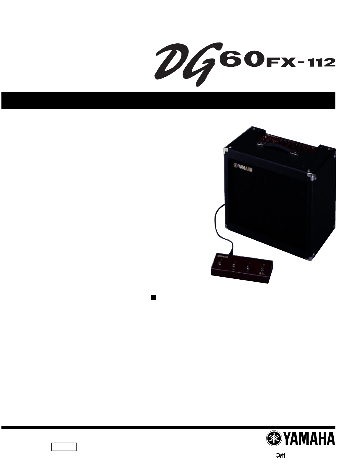
Yamaha DG60FX-112 User manual

DG60FX-112
1
SERVICE MANUAL
GA 011540
20001101-75000 1.552K-448 I.T Printed in Japan 2000.11
HAMAMATSU, JAPAN
GUITAR AMPLIFIER
CONTENTS
SPECIFICATIONS ................................................ 3/4
PANEL LAYOUT .................................... 5
CIRCUIT BOARD LAYOUT ................. 7
BLOCK DIAGRAM
............................ 8
WIRING ................................................................... 10
DISASSEMBLY PROCEDURE ............................ 11
LSI PIN DESCRIPTION .............................. 15
IC BLOCK DIAGRAM ................................... 18
CIRCUIT BOARDS ........................................ 20
TEST PROGRAM ................................. 30
ERROR MESSAGES ............................. 33
IDLING ADJUSTMENT ........................ 33
MIDI IMPLEMENTATION CHART......................................... 34
PARTS LIST
OVERALL CIRCUIT DIAGRAM
This document is printed on chlorine free (ECF) paper with soy ink.

DG60FX-112
22
IMPORTANT NOTICE
This manual has been provided for the use of authorized Yamaha Retailers and their service personnel. It has been assumed
that basic service procedures inherent to the industry, and more specifically Yamaha Products, are already known and under-
stood by the users, and have therefore not been restated.
WARNING : Failure to follow appropriate service and safety procedures when servicing this product may result in per-
sonal injury, destruction of expensive components and failure of the product to perform as specified. For
these reasons, we advise all Yamaha product owners that all service required should be performed by an
authorized Yamaha Retailer or the appointed service representative.
IMPORTANT : This presentation or sale of this manual to any individual or firm does not constitute authorization certifi-
cation, recognition of any applicable technical capabilities, or establish a principal-agent relationship of
any form.
The data provided is belived to be accurate and applicable to the unit(s) indicated on the cover. The research engineering, and
service departments of Yamaha are continually striving to improve Yamaha products. Modifications are, therefore, inevitable
and changes in specification are subject to change without notice or obligation to retrofit. Should any discrepancy appear to
exist, please contact the distributor’s Service Division.
WARNING : Static discharges can destroy expensive components. Discharge any static electricity your body may have
accumulated by grounding yourself to the ground bus in the unit (heavy gauge black wires connect to
this bus.)
IMPORTANT : Turn the unit OFF during disassembly and parts replacement. Recheck all work before you apply power
to the unit.
WARNING: CHEMICAL CONTENT NOTICE!
The solder used in the production of this product contains LEAD. In addition, other electrical/electronic and/or plastic (Where
applicable) components may also contain traces of chemicals found by the California Health and Welfare Agency (and possibly
other entities) to cause cancer and/or birth defects or other reproductive harm.
DO NOT PLACE SOLDER, ELECTRICAL/ELECTRONIC OR PLASTIC COMPONENTS IN YOUR MOUTH FOR ANY REASON WHAT
SO EVER!
Avoid prolonged, unprotected contact between solder and your skin! When soldering, do not inhale solder fumes or expose
eyes to solder/flux vapor!
If you come in contact with solder or components located inside the enclosure of this product, wash your hands before handling
food.
WARNING
Components having special characteristics are marked and must be replaced with parts having specification equal to those
originally installed.
LITHIUM BATTERY HANDLING
This product uses a lithium battery for memory back-up.
WARNING : Lithium batteries are dangerous because they can be exploded by improper handling. Observe the following pre-
cautions when handling or replacing lithium batteries.
Leave lithium battery replacement to qualified service personnel.
Always replace with batteries of the same type.
When installing on the PC board by soldering, solder using the connection terminals provided on the battery cells.
Never solder directly to the cells. Perform the soldering as quickly as possible.
Never reverse the battery polarities when installing.
Do not short the batteries.
Do not attempt to recharge these batteries.
Do not disasemble the batteries.
Never heat batteries or throw them into fire.
ADVARSEL!
Lithiumbatteri-Eksplosionsfare ved fejlagtig handtering. Udskiftning ma kun ske med batteri af samme fabrikat og type. lever det brugte
batteri tilbage til leverandren.
VARNING
Explosionsfara vid felaktigt batteribyte.
Anvand samma batterityp eller en ekvivalent typ som rekommenderas av apparattillverkaren.
Kassera anvant batteri enligt fabrikantens instruktion.
VAROITUS
Paristo voi rajahtaa, jos se on virheellisesti asennettu.
Vaihda paristo ainoastaan laitevalmistajan suosittelemaan tyyppiiin.
Havita kaytetty paristo valmistajan ohjeiden mukaisesti.
The following information complies with Dutch official Gazette 1995. 45; ESSENTIALS OF ORDER ON THE COLLECTION OF BATTERIES.
• Please refer to the diassembly procedure for the removal of Back-up Battery.
• Leest u voor het verwijderen van de backup batterij deze beschrijving.
2

DG60FX-112
3
SPECIFICATIONS
Digital Section
• Full Digital Signal Processing
• 8 Channel Preamp
• Digital Effects
• Compressor
• Chorus, Flanger, Phaser, Rotary Speaker, Tremolo
• Digital Delay, Tape Echo
• Spring Reverb, Hall Reverb, Plate Reverb
• Tap Tempo Function (Delay Time)
• Speaker Simulator (16 Types)
• External Controller Function (EXP Pedal/MIDI):8 Controllers/
Parameters
• Wah Function
• Tuner Function (Chromatic, Auto)
Analog Section
• 60 W Solid State Power Amp
• 30 cm Speaker (EMINENCE) x 1
MIDI Functions
Receive: Program Change (Program Change Table can be
created), Control Change, Bulk In
Transmit: Program Change, Control Change, Bulk Out, Merge
Out
Controller Switch
Top Panel
Push Switch x17
UP, DOWN, MANUAL, UTILITY, STORE, COMP, CHORUS,
FLANGER, PHASER, ROTARY,TREMOLO, DELAY,TAPE
ECHO, SPRING, HALL, PLATE, SP. SIM
Knob x15
AMP SELECT, GAIN, MASTER, TREBLE, MIDDLE, BASS,
PRESENCE, COMP, SPEED, DEPTH,TIME, FEEDBACK,
LEVEL, REVERB, OUTPUT
Rear Panel
Push Switch x1
POWER
Display
7 Segment LED (3 digit) x1
Push Switch LED x17
Connections/Jacks
INPUT HIGH, LOW:Standard Monaural Phone Jack
LINE OUT L/MONO, R:Standard Monaural Phone Jack
PHONES: Standard Stereo Phone Jack
POWER AMP IN:Standard Monaural Phone Jack
Foot Switch UnitTerminal: 13 pin DIN
DIGITAL OUT: COAXIAL
MIDI IN, MIDI OUT:5 pin DIN
A/D Converter
20 bit + 3 bit Floating
D/A Converter
20 bit
Sampling Frequency
48 kHz
Memory Allocations
Preset: 90
User: 90
Input Level/Impedance
INPUT HIGH: -25dBm/1M ohm
INPUT LOW:-15dBm/1M ohm
POWER AMP IN: 0 dBm/100k ohm
Output Level/Impedance
LINE OUT L/MONO, R: -3dBm/2.3k ohm
PHONES: 0dBm/47 ohm (47ohm load)
SPEAKER: 60W RMS/8 ohm
Power
U.S.and Canadian models : 120V, 60Hz
General model : 230V, 50Hz
Power Consumption
70 W
Dimensions (WxHxD)
513 x 491 x 291 mm (20.2” x 19.3” x 11.5”)
Weight
17 kg (37 lbs 8 oz)
Accessories
Foot Switch Unit
Foot Switch Special Cable
Owner’s Manual
Patch List
Foot Switch Unit
Footswitch x4 (1, 2, 3, BANK)
LED x6 (1, 2, 3, BANK x3)
Connections/Jacks
EXP. PEDAL: Standard Stereo Phone Jack
Connects main unit and foot switch:13 pin DIN
Dimensions (WxHxD) : 280 x55 x108 mm
(11.0” x 2.2” x 4.3”)
Weight :930 g (2 lbs 1 oz)

DG60FX-112
4

DG60FX-112
5
1
2
3
4
5
6
7
8
9
10
11
12
13
14
15
16
17
18
19
20
21
22
23
24
25
PANEL LAYOUT
Input Jacks (INPUT HIGH, LOW)
Peak Indicator
Amp Select Switch (LEAD1-CLEAN2)
Gain Control (GAIN)
Master Volume (MASTER)
Tone Controls
(TREBLE, MIDDLE, BASS, PRESENCE)
Output Level Control (OUTPUT)
Speaker Simulator Button (SP. SIM)
Up Button (UP)
Down Button (DOWN)
Display
Manual Button (MANUAL)
Utility Button (UTILITY)
Store Button (STORE)
Compressor Button (COMP)
Compressor Knob (COMP)
Modulation Group Effect Buttons
(CHORUS/FLANGER/PHASER
/ROTARY/TREMOLO)
Speed Knob (SPEED)
Depth Knob (DEPTH)
Delay Group Effect Buttons
(DELAY/TAPE ECHO)
Time Knob (TIME)
Feedback Knob (FEEDBACK)
Level Knob (LEVEL)
Reverb Group Effect Buttons
(SPRING/HALL/PLATE)
Reverb Knob (REVERB)
Control Panel
1 2 43
7
5 6
8
24201711 129 151310 14

DG60FX-112
6
34
35
36
37
26
27
28
29
30
31
32
33
Power Switch (POWER)
Headphones Jack (PHONES)
Line Out Jacks (LINE OUT R, L/MONO)
POWER AMP IN Jack
Foot Switch UnitTerminal (FOOT SW)
MIDI OUT Jack
MIDI IN Jack
Digital Out Jack (DIGITAL OUT)
Foot Switches 1, 2, 3
Bank Switch (TAP/BANK/TUNER)
EXP Pedal Jack (EXP. PEDAL)
UnitTerminal
Rear Panel
Top Panel Rear panel
26 27 2928 30
31 32 33
34 35
36 37
Foot Switch Unit

DG60FX-112
7
CIRCUIT BOARD LAYOUT
4/8 7/8 6/8 5/8
1/8
2/8
3/8
(PN1/2)
MAIN MAIN MAIN MAIN
MAIN
DM
MAIN
MAIN
FRONT
(ANALOG8/8)REAR
(PN2/2)SW, LED
Foot Switch

DG60FX-112
8
BLOCK DIAGRAM
(PN1/2)
3/8
IC1
IC12
(DM-CN1)
(FRONT-CN304)
(DM-CN2)
(FRONT-CN303)
IC2,IC3 IC9 IC8 IC10,IC11
IC401 IC402
W401
CN101
IC401
+
+
57 57
13
IC102
-
-21
IC103
1
-
2
IC102
-
67
IC103
6-7IC104
CN103
CN103 CN102
FRONT
MAIN
DM
FRONT
A
A'

DG60FX-112
9
KEC-54207
(DM-CN3)
(FRONT-CN302)
W701
CN306
C
10,IC11
CN103
W502
CN102
IC501
+75IC501
+
31
IC502
+
13
IC502
+
57
REAR
(1/8, 2/8, 4/8~7/8)
MAIN
FRONT
SW, LED
A
A'

DG60FX-112
10
WIRING
SPEAKER
CN603
CN602
CN301
CN601
AC
TRANSFORMER
POWER
W502 W501
CN304 CN303 CN302 CN305
W701CN306
CN401 W401
CN4
W503
CN1 CN2 CN3
CN103
CN104
W612
W608 CN607
W606
W604
W601 W603
W611
W610
W602
4/8 7/8
W609
6/8
W607
5/8
W605
1/8
2/8
3/8
(PN1/2)
CN102
CN101
MAIN MAIN MAIN MAIN
DM
MAIN
MAIN
(ANALOG8/8)
REAR
MAIN
(PN2/2)
SW, LED
FRONT
FOOT SWITCH OVERALL ASSEMBLY

DG60FX-112
11
DISASSEMBLY PROCEDURE
Fig.1
A. External components
1. Handle Assembly
1-1. Remove the two (2) screws marked [70].The handle
assembly can then be removed. (Fig.1)
2. Corner fitting
2-1. Remove the two (2) screws marked [50].The corner
fitting can then be removed. (Fig.1)
3. Leg
3-1. Remove the screw marked [110].The leg can then
be removed. (Fig. 1)
[50]: Oval Head Tapping Screw 3.5X16 MFNI33 (V383360)
[70]: Oval Head Screw 0X25 FNM3-2B (V374370)
[110]: Truss Head Tapping Screw-1 4.0X20 MFZN2BL (O374729)
[110]
[70]
[50]
[50]

DG60FX-112
12
Fig.2
4. Removal of stereo amplifier unit
4-1. Remove the four (4) screws marked [80] and the
four (4) washers marked [90] from the back plate
and then remove the back plate.(Fig. 2)
4-2. Remove the six (6) screws marked [30] and the six
(6) washers marked [40] from the top of the main
unit.The pre main unit can then be removed.(Fig.2)
5. Removal of speaker
5-1. Remove the pre main unit.(See Procedure 4.)
5-2. Remove the four (4) screws marked [70]. The
speaker can then be removed.(Fig. 2)
[30]: Oval Head Screw 5.0X35 MFC2BL (V374938)
[40]: Washer 5S MFC2BL (EW30002)
[70]: Hexagonal Nut 4.0 MFZN2Y (O376090)
[80]: Oval Head Tapping Screw 4.0X30 MFC2BL (V374940)
[90]: Washer 4S MFC2BL (V389020)
B. Pre main unit
6. FRONT circuit board (PN 1/2),MAIN circuit board (3/8)
6-1. Remove the pre main unit.(See Procedure 4.)
6-2. Remove the five (5) screws marked [110] and then
remove the panel. (Fig.3)
6-3. Remove the seven (7) screws marked [290], eight
(8) knobs marked [310], fifteen (15) hexagonal nuts,
three (3) screws marked [50]. The FRONT circuit
board (PN 1/2) can then be removed. (Fig. 3)
6-4. Remove the two (2) hexagonal nuts marked [210]
and the two (2) flat washers marked [220].The MAIN
circuit board (3/8) can then be removed. (Fig.3)
[30]
[40] [30]
[40]
[70]
[80]
[90] [90]
[80]
[70]

DG60FX-112
13
7. DM, MAIN circuit boards (1/8, 2/8, 4/8, 5/8, 6/8,
7/8), heat sink
7-1. Remove the pre main unit. (See Procedure 4.)
7-2. Remove the panel.(See Step 6-2.)
7-3. Remove the four (4) hexagonal nuts marked [140]
and four (4) screws marked [50A].The MAIN circuit
board (2/8) can then be removed. (Fig.4)
7-4. Remove the five (5) screws marked [50B] and the
three (3) screws marked [55] from the rear panel.
The DM circuit board can then be removed.(Fig. 4)
7-5. Remove the four (4) screws marked [50C].The MAIN
circuit board (1/8) can then be removed.(Fig.4)
7-6. Remove the four (4) screws marked [130].The MAIN
circuit boards (4/8, 5/8, 6/8, 7/8) can then be
removed. (Fig. 4)
7-7. Remove the four (4) screws marked [110A].The heat
sink can then be removed. (Fig.4)
Fig.3
[50]: Bind Head Tapping Screw-B 3.0X8 MFZN2BL (EP600190)
[110]: Bind Head Tapping Screw-C A4.0X8 MFZN2BL (VC688900)
[210]: Hexagonal Nut 9.0 12X2 MFNI33 (LX200060)
[220]: Flat Washer 9X14 0.5 FNM3 (VL802300)
[110]
4/8 7/8 6/8 5/8
1/8
[110]
[210]
[220]
[290][310][290][290] MAIN 3/8FRONT (PN1/2)
[50]
MAIN MAIN MAIN MAIN
MAIN
DM

DG60FX-112
14
Battery VN103500
VN103600(Battery holder for VN103500)
• Notice for back-up battery removal
Push the battery as shows in figure,
then the battery will pop up.
Fig.4
[50]: Bind Head Tapping Screw-B 3.0X8 MFZN2BL (EP600190)
[55]: Bind Head Tapping Screw-P 3.0X12 MFZN2BL (VC161100)
[110]: Bind Head Tapping Screw-C A4.0X8 MFZN2BL (VC688900)
[130]: Bind Head Screw SP 3.0X12 MFZN2Y (VB763800)
[140]: Hexagonal Nut 12.0 14X2 MFC2BL (VD794100)
8. Power transformer
8-1. Remove the pre main unit. (See Procedure 4.)
8-2. Remove the panel. (See Step 6-2.)
8-3. Remove the four (4) screws marked [110B].The
transformer can then be removed.(Fig. 4)
[140] [140]
[50A] [50A] [55]
[50B]
[50B]
[50C]
[50C]
[50C]
[110B] [110A] [50B][130] [110A] [130] [110A] [130] [110A] [130]
DM
MAIN 1/8
MAIN 2/8
Power
Transformer
Rear panel

DG60FX-112
15
C. Foot switch
9. Foot switch
9-1. Remove the six (6) screws marked [110A] and then
remove the bottom plate. (Fig.5)
9-2. Remove the two (2) screws marked [110B] and
hexagonal nuts marked [90] and then remove the
REAR circuit board (MAIN 8/8). (Fig. 5)
9-3. Remove the four (4) hexagonal nuts from the foot
switch.The SW, LED circuit board (PN2/2) can then
be removed. (Fig. 5)
Fig.5
[90]: Hexagonal Nut 9.0 12X2 MFNI33 (LX200060)
[110]: Bind Head Tapping Screw-B 3.0X8 MFZN2BL (EP600190)
[110A]
[110A]
[110A]
[110A]
[90]
[110B]
Hexagonal nut Hexagonal nut
Foot switch
REAR (MAIN 8/8)
SW, LED
(PN2/2)
View A

DG60FX-112
16
LSI PIN DESCRIPTION
PIN
NO.
1
2
3
4
5
6
7
8
9
10
11
12
13
14
15
16
17
18
19
20
21
22
23
24
25
26
27
28
29
30
31
32
33
34
35
36
37
38
39
40
41
42
43
44
45
46
47
48
49
50
I/O
O
O
I
I
I
I
I
I
I
I
O
O
O
I
I
O
I
I/O
I/O
I/O
I/O
I/O
I/O
I/O
I/O
I/O
I/O
I/O
I/O
I/O
I/O
I/O
I/O
O
O
O
O
O
O
O
O
O
O
O
O
PA6
PA7
VCC
PB0
PB1
PB2
PB3
PB4
PB5
PB6//DREQ0
PB7//DREQ1
/RESO
VSS
P90/TXD0
P91/TXD1
P92/RXD0
P93/RXD1
P94/SCK0
P95/SCK1
P40/D0
P41/D1
P42/D2
P43/D3
VSS
P44/D4
P45/D5
P46/D6
P47/D7
D8
D9
D10
D11
D12
D13
D14
D15
VCC
A0
A1
A2
A3
A4
A5
A6
A7
VSS
A8
A9
A10
A11
NAME
Port A
Address bus
Power supply
Port B
Reset
Ground
Transmit data (MIDI OUT)
KSN-ACK
Receive data (MIDI IN)
KSN-RX
Port 9
Port 9
(Ground)
Data bus
Power supply
Address bus
(Ground)
FUNCTION PIN
NO.
51
52
53
54
55
56
57
58
59
60
61
62
63
64
65
66
67
68
69
70
71
72
73
74
75
76
77
78
79
80
81
82
83
84
85
86
87
88
89
90
91
92
93
94
95
96
97
98
99
100
I/O
O
O
O
O
O
O
O
O
I
I
I
O
I
I
I
I
O
O
O
O
O
I
I
I
I
I
I
I
I
I
I
I
I
O
O
O
O
O
I
I
I
O
O
O
A12
A13
A14
A15
A16
A17
A18
A19
VSS
P60//WAIT
P61//BREQ
P62//BACK
Ø
/STBY
/RES
NMI
VSS
EXTAL
XTAL
VCC
/AS
/RD
/HWR
/LWR
MD0
MD1
MD2
AVCC
VREF
P70/AN0
P71/AN1
P72/AN2
P73/AN3
P74/AN4
P75/AN5
P76/AN6
P77/AN7
AVSS
P80
P81//CS3
P82//CS2
P83//CS1
P84//CS0
VSS
PA0
PA1
PA2
PA3
PA4
PA5
NAME
Address bus
Ground
Port 6
Øout
Stand-by mode signal
Reset
Non-maskable interrupt
Ground
Clock
Clock
Power supply
Address strobe
Read strobe
Write strobe (High)
Write strobe (Low)
Mode select
Analog power supply
Reference voltage
Analog data input (EQ)
Analog input (EQ)
Analog data input
Analog input (CS)
Analog data input (BEND)
Analog input (MOD)
Analog input (FC)
Analog input (BAT)
Analog ground
Port 8
Chip select
Ground
Port A
FUNCTION
HD6413002FP16 (XQ375A00) CPU <H8/3002>
DM: IC12
PIN
NO. I/O FUNCTIONNAME PIN
NO. I/O FUNCTIONNAME
1
2
3
4
5
6
7
8
Vss
MCLK
DM0
DM1
RES
WCIN
DIN
V
DD
I
I
I
I
I
I
Ground
Master clock input
DIN/BCLK/WCLK format select
DM1,DM0=0,0 DSP,LDSP (64 bit,LSB first)
DM1,DM0=0,1stereo,DSP (64 bit,MSB first)
DM1,DM0=1,0 DSP2 (128 bit,MSB first)
DM1,DM0=1,1 BB (64 bit,MSB first)
System reset
Word clock input
Digital audio serial data input
Power supply (+5 V)
9
10
11
12
13
14
15
16
MUTE
VFL
CCK
CIN
CLD
CNTR
CSM
DOUT
I
I
I
I
I
I
I
O
Mute
Validity flag
C,U bit clock input/C bit data input
C,U bit data input/U bit data input
End of C,U bit input/16,20 bit/24 bit select
32 bit counter reset/Top of block
Channel status input mode select
CSM=0 Asynchronous mode
CSM=1 Synchronous mode
Digital interface formatted data output
YM3437C-F (XM530A00) DIT2 (Digital Format Interface Transmitter)
DM: IC17

DG60FX-112
17
PIN
NO. I/O FUNCTIONNAME PIN
NO. I/O FUNCTIONNAME
1
2
3
4
5
6
7
8
9
10
11
12
13
14
15
16
17
18
19
20
21
22
23
24
25
26
27
28
29
30
31
32
33
34
35
36
37
38
39
40
41
42
43
44
45
46
47
48
49
50
51
52
53
54
55
56
57
58
59
60
61
62
63
64
65
66
67
68
69
70
71
72
73
74
75
76
77
78
79
80
81
82
83
84
85
86
87
88
Vdd
Vss
XI
XO
Vdd
/SYNCI
/SYNCO
Vdd
CKI
CKO
CKSEL
Vss
MCKS
/SSYNC
/IC
/TEST
BTYP
/IRQ
TRIG
Vdd
Vss
/CS
/WR
/RD
CA7
CA6
CA5
CA4
CA3
CA2
CA1
Vss
Vdd
CD15
CD14
CD13
CD12
CD11
CD10
CD09
CD08
CD07
CD06
Vss
Vdd
Vdd
CD05
CD04
CD03
CD02
CD01
CD00
/WAIT
Vss
SI0
SI1
SI2
SI3
SI4
SI5
SI6
SI7
Vss
Vdd
SO0
SO1
SO2
SO3
SO4
SO5
SO6
SO7
Vss
DB00
DB01
DB02
DB03
DB04
DB05
DB06
DB07
DB08
DB09
DB10
DB11
DB12
Vdd
Vdd
I
O
I
O
I
O
I
I
I
I
I
I
O
I/O
I
I
I
I/O
I/O
I/O
I/O
I/O
I/O
I/O
I/O
I/O
I/O
I/O
I/O
I/O
I/O
I/O
I/O
I/O
I/O
I/O
I/O
I/O
I/O
I/O
O
I
I
I
I
I
I
I
I
O
O
O
O
O
O
O
O
I/O
I/O
I/O
I/O
I/O
I/O
I/O
I/O
I/O
I/O
I/O
I/O
I/O
Power supply (3.3 V)
Ground
System master clock input (60 MHz or 30 MHz)
System master clock output (High or 30 MHz)
Power supply (5 V)
Sync. signal input
Sync. signal output
Power supply (5 V)
System clock input (30 MHz)
System clock output (30 MHz)
System master clock select (0: 60 MHz, 1: 30 MHz)
Ground
Serial I/O master clock input (128 x Fs)
Serial I/O Sync. signal output
Initial clear
Test mode setting (0: Test, 1: Normal)
Data bus type select (0: 8 bit, 1: 16 bit)
IRQ output
Trigger signal input/output
Power supply (5 V)
Ground
chip select signal input
Write signal input
Read signal input
Address bus of internal register
Ground
Power supply (3.3 V)
Data bus of internal register
Ground
Power supply (3.3 V)
Power supply (5 V)
Data bus of internal register
WAIT output
Ground
Serial data input
Ground
Power supply (5 V)
Serial data output
Ground
Parallel data bus
Power supply (5 V)
Power supply (3.3 V)
89
90
91
92
93
94
95
96
97
98
99
100
101
102
103
104
105
106
107
108
109
110
111
112
113
114
115
116
117
118
119
120
121
122
123
124
125
126
127
128
129
130
131
132
133
134
135
136
137
138
139
140
141
142
143
144
145
146
147
148
149
150
151
152
153
154
155
156
157
158
159
160
161
162
163
164
165
166
167
168
169
170
171
172
173
174
175
176
Vss
DB13
DB14
DB15
DB16
DB17
DB18
DB19
DB20
DB21
DB22
Vss
Vdd
DB23
DB24
DB25
DB26
DB27
DB28
DB29
DB30
DB31
TIMO/DBOB
Vss
Vdd
DA00
DA01
DA02
DA03
DA04
DA05
DA06
DA07
Vss
DA08
DA09
DA10
DA11
DA12
DA13
DA14
DA15
Vss
Vdd
(n.c)
Vdd
DA16
DA17
DA18
DA19
DA20
DA21
DA22
DA23
Vss
DA24
DA25
DA26
DA27
DA28
DA29
DA30
DA31
Vdd
Vss
A00
A01
A02
A03
A04
A05
A06
A07
A08
A09
Vss
Vdd
A10
A11
A12
A13
A14
A15/RAS
A16/CAS
A17/CE
/WE
/OE
Vdd
I/O
I/O
I/O
I/O
I/O
I/O
I/O
I/O
I/O
I/O
I/O
I/O
I/O
I/O
I/O
I/O
I/O
I/O
I/O
I/O
I/O
I/O
I/O
I/O
I/O
I/O
I/O
I/O
I/O
I/O
I/O
I/O
I/O
I/O
I/O
I/O
I/O
I/O
I/O
I/O
I/O
I/O
I/O
I/O
I/O
I/O
I/O
I/O
I/O
I/O
I/O
I/O
O
O
O
O
O
O
O
O
O
O
O
O
O
O
O
O
O
O
O
O
Ground
Parallel data bus
Ground
Power supply (3.3 V)
Parallel data bus
Timing signal output/ Parallel data bus output/ input
Ground
Power supply (5 V)
Memory data bus
Ground
Memory data bus
Ground
Power supply (3.3 V)
Not used
Power supply (5 V)
Memory data bus
Ground
Memory data bus
Power supply (5 V)
Ground
Memory address (SRAM, PSRAM, DRAM)
Ground
Power supply (3.3 V)
Memory address (SRAM, PSRAM, DRAM)
Memory address (SRAM, PSRAM)
Memory address (SRAM, PSRAM), /RAS (DRAM)
Memory address (SRAM, PSRAM), /CAS (DRAM)
Memory address (SRAM), /CE (PSRAM)
Memory write enable signal
Memory output enable signal
Power supply (5 V)
YSS910-S (XV988A00) DSP6 (Digital Signal Processor)
DM: IC8, IC9

DG60FX-112
18
IC BLOCK DIAGRAM
PIN
NO.
1
2
3
4
5
6
7
8
9
10
11
12
13
14
I/O
I
I
I
I
I
I
-
-
I
I
I
I
I
O
VREFH
VREFL
AINR+
AINR-
AINL+
AINL-
VA
AGND
DIF0
DIF1
LRCK
SCLK
SDTI
SDTO
NAME
Positive Voltage Reference Input, VA
Negative Voltage Reference Input, AGND
Rch Analog Positive Input
Rch analog Negative Input
Lch Analog Positive Input
Lch analog Negative Input
Analog Power Supply
Analog Ground
Audio Data Interface Format
Input/Output Channel Clock
Audio Serial Data Clock
Audio Serial Data Input
Audio Serial Data Output
FUNCTION PIN
NO.
15
16
17
18
19
20
21
22
23
24
25
26
27
28
I/O
I
I
I
I/O
I/O
I
-
-
I
I
I
O
O
O
MCLK
DEM0
DEM1
TST3
TST2
TST1
VD
DGND
/PWDA
/PWAD
CMODE
AOUTL
AOUTR
VCOM
NAME
Master Clock Input
De-emphasis Frequency Select
Test Pins (Pull Down Pins)
Digital Power Supply
Digital Ground
DAC power-Down Mode
ADC power-Down Mode
Master Clock Select (“H”:384 fs,“L”:256 fs)
Lch Analog Output
Rch Analog Output
Common Voltage Output, VA/2
FUNCTION
AK4520A-VF-E2 (XT802A00) DAC & ADC
DM: IC104
11A
2
3
4
5
6
7
1B
1Y
2A
2B
2Y
GND 8
9
10
11
12
13
14 V
CC
4B
4A
4Y
3B
3A
3Y
74AHC32DT
(
XZ103A00
)
DM: IC5, IC6
OR
74HC08DT(XZ108A00)
DM: IC7
AND
74HC244DT(XZ109A00)
DM: IC14, IC15, IC16
Bus Buffer
74HC164DT(XZ112A00)
DM: IC109
SHIFT REGISTANT
NJM072M(XC458A00)
DM: IC101
OP AMP
1
2
3
4
5
6
7
13
12
11
10
9
8
141A
1B
1Y
2Y
2A
2B
Vss
VDD
4B
4A
4Y
3Y
3A
3B
74HC175DT(XZ113A00)
DM: IC110
D-FF
Output A
Inverting
Input A
Non-Inverting
Input A
–DC Voltage
Supply
+DC Voltage
Supply
Output B
Inverting
Input B
Non-Inverting
Input B
1
2
3
4
8
7
6
5
–+
–+
–V
1G
1A1
2Y4
1A2
2Y3
1A3
2Y2
1A4
2Y1
1 20
2 19
3 18
4 17
5 16
6 15
7 14
8 13
9 12
10 11
VDD(Vcc)
2G
1Y1
2A4
1Y2
2A3
1Y3
2A2
1Y4
2A1(GND)Vss
1
2
3
4
5
6
7
15
14
13
12
11
10
16CL
1Q
1Q
1D
2D
2Q
2Q
VDD
4Q
4Q
4Q
3D
3Q
3Q
8 9Vss CK
Q
Q D
CK
CL
D Q
CK
C LQ
QCK CK
CL QCL
Q
D
QD
1
2
3
A
QA QA
4QB QB
5QC QC
6QD QD
7GND
BB
14
13
12
VCC
QGQG
11 QFQF
10 QEQE
9 CLEARCLEAR
8 CLOCK
QH
CK
QH
OUTPUTS
OUTPUTS
SIRIAL
INPUT A
A

DG60FX-112
19
TC74HC4040F
(
XR684A00
)
DM: IC108
B. COUNTER
TC74HC4040DT
(
XZ111A00
)
DM: IC108
12-Stage Binary Ripple Counter
74HC374DT(XZ102A00)
DM: IC301~IC307
D-FF
74HC4052DT(XZ101A00)
DM: IC308, IC309
Multiplexer
CK
1
2
3
4
5
6
7
Q12 Q12
Q6 Q6
Q5 Q5
Q7 Q7
Q4 Q4
Q3 Q3
Q2 Q2
16
15
14
13
12
11
10
VDD
Q11
Q11
Q10
Q10
Q8
Q8
Q9
Q9
CLR
CL
8
Vss 9Q1
Q1
Input Pulses ( )
Q
D
Q
D
Q
D
Q
DCK
OE OE
OE
OE OE
OEOE
OE
Q
D
Q
D
Q
D
Q
DCK
CK
CK
CK CK
CK
CK
1OUT PUT
CONTROL
2
3
4
5
6
7
8
9
10
1Q
1D
2D
2Q
3Q
3D
4D
4Q
GND 11
12
13
14
15
16
17
18
19
20 V
CC
8Q
8D
7D
7Q
6Q
6D
5D
5Q
CLOCK
1
2
3
4
5
6
7
OY
2Y
Y-COM
3Y
1Y
INH
V
EE
16
15
14
13
12
11
10
V
DD
2X
1X
X-COM
OX
3X
A
2Y
Y-COM
3Y
1Y
INH
2X
0Y B
1X
X-COM
0X
3X
A
8
V
SS
9B
74HCU04DT (XZ110A00)
DM: IC107
INVERTER
11A
2
3
4
5
6
7
1Y
2A
2Y
3A
3Y
V
SS
8
9
10
11
12
13
14 V
DD
6A
6Y
5A
5Y
4A
4Y
NJM5532M (XC011A00)
DM: IC102, IC103, IC106
OP AMP
NE5532P (IG102500)
DM: IC502
OP AMP
NJM4556AMT1 (XQ138A00)
DM: IC105
OP AMP
1
2
3
4
8
7
6
5
A OUT
A+IN
V+
B OUT
B+IN
A IN
V
B IN
NJM4556AD (XQ824A00)
MAIN: IC501
OP AMP
1
2
3
4-V
+V 8
7
6
5
Output A
Non-Inverting
Input A
-DC Voltage Supply
+DC Voltage
Supply
Output B
Inverting
Input B
Non-Inverting
Input B
Inverting
Input A
+-
+-
1
2
3
4-V
8
7
6
5
Output A +V
Non-Inverting
Input A
-DC Voltage Supply
+DC Voltage
Supply
Output B
Inverting
Input B
Non-Inverting
Input B
Inverting
Input A
+-
+-
MB3790PF(XR967A00)
DM: IC4
ASSP
N.C.
V
BAT1
V
OUT
V
OUT
V
BAT2
ALARM1
GND
CONTROL
N.C.
V
IN
V
IN
V
SENSE
C
T
RESET
RESET
ALARM1
1
2
3
4
5
6
7
8
10
9
13
12
11
16
15
14
2
3
4
5
6
7
8
9
10
11
12
16
14
13
C
T
V
BAT2
V
BAT1
ALARM2
RESET
RESET
ALARM1
V
OUT
V
OUT
V
IN
V
IN
V
SENSE
CONTROL
GND
590kΩ
240kΩ
1.24V
Reference
Voltage
Power Supply
Circuit
SQ
R
R
CN
0.5Ω
100Ω
SBD
2.65V
2.37V
500Ω
V
IN
V
IN
V
OUT
V
OUT
3µA
V th:3V
V th:1.5V

DG60FX-112
20
CIRCUIT BOARDS
DM Circuit Board
to P
N
A
A'
CN101:
to MAIN3/8-W401
CN103:
to PN1/2-CN301
CN102:
to MAIN2/8-W502
Battery VN103500
VN103600(Battery holder for VN103500)
• Notice for back-up battery removal
Push the battery as shows in figure,
then the battery will pop up.
Other manuals for DG60FX-112
2
Table of contents
Other Yamaha Musical Instrument Amplifier manuals

Yamaha
Yamaha AR-1500 User manual

Yamaha
Yamaha KS531 User manual

Yamaha
Yamaha VA-2 User manual

Yamaha
Yamaha VA-10 User manual

Yamaha
Yamaha B100-112III User manual

Yamaha
Yamaha VX-15 User manual

Yamaha
Yamaha F-20 User manual

Yamaha
Yamaha GA15II User manual

Yamaha
Yamaha VR-4000 User manual

Yamaha
Yamaha THR Series User manual

Yamaha
Yamaha AR-PRO User manual

Yamaha
Yamaha DG60-112 User manual

Yamaha
Yamaha DG60FX-112 User manual

Yamaha
Yamaha KS531 User manual

Yamaha
Yamaha S112 User manual

Yamaha
Yamaha HY-10GII Budokan User manual

Yamaha
Yamaha DG130 User manual

Yamaha
Yamaha GA-15 User manual

Yamaha
Yamaha THR Series User manual

Yamaha
Yamaha AR-1500 User manual