WTO
SERVICE
PERSONAL
1.
Critical Compnentt Information.
Components having special characteristics are marked
A
and must be replaced with parts having specifications
equal tothose originally installed.
2.
LeakageCurrent Measurement
(For
120V
Model Only).
When service has been completed,
it
is
imperativethat you verify that all exposed conductivesurfaces are properly
insulatedfrom supply circuits.
EQUIPMENT AC LEAKAGE TESTER
@
Meter impedance should be equivalent to
1500
UNDER TEST
or
EQUIVALENT
ohm shuntedby
0.1
5pF.
@
Leakage current must not exceed 0.5mA.
B
Be sure to test for leakage with the
AC
plug in
WALL
both polarities.
OUTLET INSULATING TABLE
-
IISPECIFSCATIONS
FM
SECTION
Tuning Range
.............
87.6
-
108.OMHz
50dB Quieting Sensitivity
............
Mono (DX) 1.6pV (15.3dBf)
.........
(NR ON) 1.2pV (12.8dBf)
Stereo (DX)
............
20pV (37.2dBf)
..........
(NR ON) 1OpV (3i.2dBf)
hbleSensitivity
(IHFMono) 75a
........
.0.9~V(10.3dBf)
UsableSensitivity (DIN)
............
Mono (SIN26dB).
.l
.OpV (E)
............
Stereo (SIN46dB) .3.OpV (E)
I-e Rarpoma Ratio
...............
9548
................
IF
Rslponro
Ratio
.l
15dB
............
Spurious R-ms Ratio.
.l
l
OdB
...............
AMSuppression Ratio 70dB
Capture Ratio
Local
.......................
1.2dB
Alternate Channel Selectivity
DX
.................
.85dB (U,C,R,A)
Selectivity (twoSignak)(DIN40kHz Dev.)
......................
DX 70dB (E)
Adjacent ChannelSelsctivity
DX
..................
20dB (U,C,R,A)
Signal to Noise Ratio (IHF)
................
Mono .94dB (U,C,R,A)
...............
Stereo :86dB (U,C,R,A)
Signalto Nobe Ratio
...........
(DIN-Weighted) Mono 88dB (E)
..........
Stereo. 80dB (E)
Harmonic Distortion
.
Mono 100Hz. .DX0.03%, Local 0.02% (U,C,R,A)
..
1kHz .DX0.15%, Local 0,03%(U,C,R,A)
6kHz
..
.DX0.4%, Local 0.06% (U,C,R,A)
Stereo lM3Hz
.
.DX0.5%, Local 0.04% (U,C,R,A)
1kHz
..
.DXO.5%, Local 0.03% (U,C,R,A)
6kHz.
.
.DX0.8%, Local 0.07% IU,C,R,AI
(4OkHz Dev)
Stereo 100Hz
......
DX0.5%, Local 0.05% (E)
l
kHz
.......
DX 0.5%. Local 0.04% (El
.....
6.3kHz. OX 0.5%, Local 0.08% (E)
Strreo
Separation (IkHz)(Local)
mkHz.
a........
.65dB
1kHz.
..........
.65dB (U,C,R,A)
60dB
(E)
10kHz
...........
50dB (U,C,R,A)
40dB
(E)
F-affiy
Raporar
0+O.~d9
.
50Hz to lOkHz
...............
-0.3
Subcarrier Product Ratio
.............
65dB
MetatSaturation Level
.........
-3mV(75dBf)
AM
SECTION
Tuning Range
........
.510
-
1620kHz (U,C,R)
513
-
1620kHz (E.A,R)
UsableSansitivity
.................
,250pV
Selectivity..
....................
30dB
Signal to
NobRatio.
...............
55dB
Image RwnseRatio
...............
40dB
Spurious Response Ratio.
.............
50dB
Distortion (400Hz).
.................
0.2%
AUDIO SECTION
Output' Levelllmpedance (HIGH)
FM(100%MOD, 1kHz)
....
1V/2ka(U,C,R,A)
1.6VI2kS2
(E)
.........
FM (30%MOD, 400Hz) 0.3VIZkn
.....
REC CAL (50%MOD, 333Hz) 0.5V12kn
.,
Output Level/lmpedanee(LOW)
i
FM (100%MOD, IkHz)
.
.
0.5VI2.5ka (U,C,R,A)
0.8V12.5kn
(E)
AM (100%MOD,
l
kHzl
.......
0.15V12.5kSZ
REC CAL (50%MOD, 333Hz)
...
0.25VI2.5kn
GENERAL
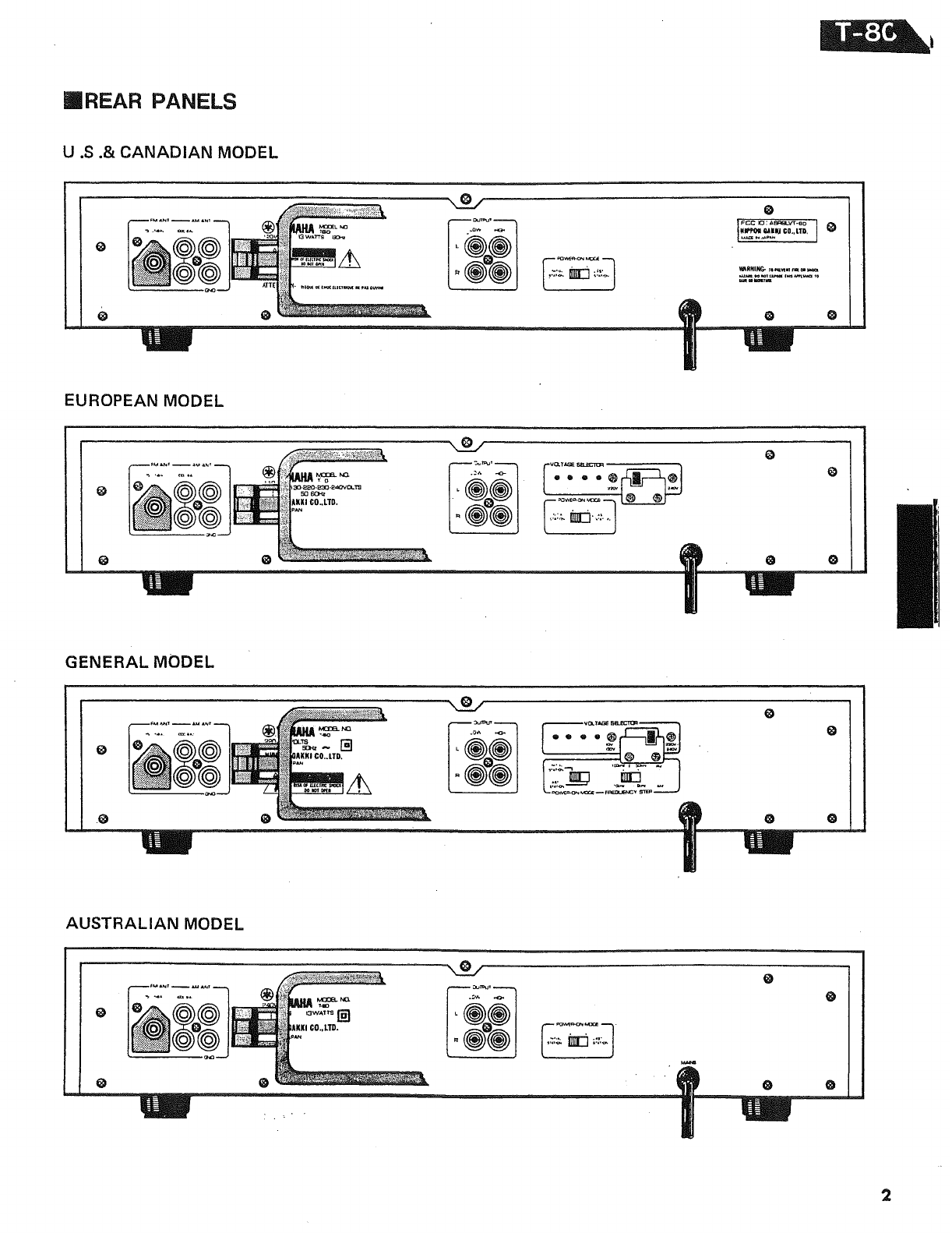
Power Supply
........
U.S.
&
Canadian Models 120V, 60Hz
.........
General Model. l1
01120V, 50/60Hz
220/240V, 50/60Hz
............
EuropeanModel. 220V, 50Hz
+,.K
,
240V, 50Hz
............
Australian Model 240V. 50Hz
Power Cbnspmption-
U.S.
&
Canadian Models
.............
13W
..................
General Model. 13W
.
.................
EuropeanModel. 13W
.................
Australian Model 12W
Dimemion(WX~D)
.
435
X
93.5
X
357rnm (U,C,R,A)
(17-718"
X
3-1
132"
X
14-1116")
435
X
93.7
X
357mm
(E)
(19-118"
X
3-1/32''
X
14-1/16")
Weight-.
........................
5kg
(Illbs)
Specificationssubject to change without notice
MARKET
U: U.S.-Model
C: ~anadbnModel
R: General Model
,>.
:'.
.,-:
--,
'
'.
,
.
.,
..:r
~g&+>*%&&&gF$g-&?;~2
A: Australian Model
J: Japanese Model
-
.
--
.
-.
.
-.
.,-
.>
.
-1..