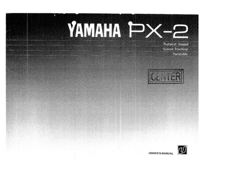
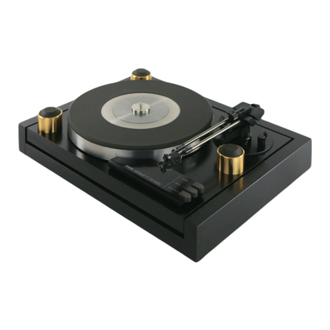
Yamaha PX-2 User manual

-l
<
—
=
<
=
a
OWNER

a
Mo
P;
YAMAHA
thanks
and
congratulates
you
on
your
purchase
of
the
YAMAHA
Linear
Tracking
Stereo
Turntable
Unit,
PX-2.
The
PX-2
uses
for
its
tonearm
section
a
linear
tracking
straight
arm
with
excellent
tracking
ability,
in
addition
to
a
direct
drive
turntable
driven
by
a
DC
4-phase,
8-pole
coreless
Hall
motor
with
a
starting
torque
of
not
less
than
1
kg-cm.
Easy-to-operate
because
of
its
fully
automatic
control
functions,
the
PX-2
represents
the
best
in
record
playing
systems.
CONTENTS
Features
oo
oo
rati
a
A
EE
anve
ea
a
CAUTION
-
Read
This
First
..............
3
STEN
4
FAZER
e
5
Identification
and
Functions
of
Controls.]....
7
p
ae
Gide
9
10
How
to
Play
Discs
.
SKU
E
chee
pin
By
ka
Aa
ee
SU
SÈ
11
EE
VASE
12
né
kona
KA
ei
e
intro
13
14
Schematic
Diagram

FEATURES
Linear
Tracking
Straight
Arm
Employing
a
linear
tracking
arm
that
boasts
a
horizontal
tracking
error
angle
of
within
+0.15°,
offset
angle
and
inside
force
of
“0”,
the
PX-2
features
reproduction
of
clearer
sounds
with
less
distortion
than
conventional
Swing
type
tonearms.
And
because
of
its
tonearm
height
adjusting
mechanism,
it
enables
stroke
changes
within
+4mm,
and
accepts
practically
all
kinds
of
cartridges
currently
available
on
the
market.
Fully
Automatic
Control
Mechanisms
By
intergrating
the
disc-size
selector
with
the
PLAY
switch
of
the
turntable,
the
unit
is
provided
not
only
with
automatic
control
functions
that
enable
one-touch
AUTO
LEAD-IN,
AUTO-RE-
TURN
and
REPEAT
play,
but
also
with
manual
control
functions
that
enable
speed
change,
CUE-
ING
UP,
CUEING
DOWN
and
LEAD-IN
and
LEAD-OUT
without
opening
the
dust
cover,
Quartz
Oscillator
Phase-Locked
Turntable
The
speed
of
revolution
of
the
DC
4-phase,
8-pole
careless
Hall
motor
(Starting
torque:
Not
less
than
1
kq-cm)
is
locked
by
a
PLL
(Phase
locked
loop)
mechanism,
which
uses
the
oscillat-
ing
frequency
of
a
quartz
crystal
oscillator
as
its
reference
frequency.
Freedom
from
tempera-
ture-
and
time-induced
drift
and
temporal
changes
ensures,
stable
and
powerful
rotation
of
the
turntable
with
speed
accuracy
as
high
as
+20
ppm,
or
better.
When
steady
rotation
of
the
platter
is
achieved,
the
LOCKED
indicator
lights
up
to
indi-
cate
phase-lock.
Heavyweight
Platter
and
Mat
This
platter,
which
measures
31
cm
in
diameter,
weights
2.1kg
and
has
a
moment
of
inertia
of
270
kg-cm“
(both
figures
including
the
rubber
mat),
Wow
and
flutter
have
been
suppressed
to
the
minimum
and
smooth
rotation
ensured.
Heavyweight
Cabinet
and
Dust
Cover
The
cabinet
is
made
of
5
mm-thick
aluminum
diecast
panels
featuring
high
rigidity.
The
heavy-
weight-class
body
weights
17
kg
in
total.
The
dust
cover
is
made
of
5
mm-thick,
1.3
kg.
This
design
protects
the
turntable
unit
from
harmful
external
vibrations
and
provides
resistance
against
‘howling’
(acoustic
feedback
from
speakers).
Other
Features
Other
features
include
a
constant-voltage
power
circuit
providing
sufficient
allowance
and
operat-
ing
properties.
In
addition,
the
PX-2
has
been
designed
to
provide
the
user
optimum
ease
of
use,
with
many
features
exclusive
to
Yamaha.
At
Yamaha,
we're
always
a
few
steps
ahead
of
other
audio
makers.
WARNING
To
prevent
fire
or
shock
hazard,
do
not
expose
this
appliance
to
rain
or
moisture.
IMPORTANT!
Please
record
the
serial
number
of
your
unit
in
the
space
below:
Model
Name:
PX-2
Serial
No.
The
serial
number
is
located
on
the
rear
of
the
chassis.
Special
Instructions
for
British
Model
IMPORTANT!
|
The
wires
in
the
mains
lead
are
coloured
in
accordance
with
the
following
code:
Blue:
NEUTRAL
Brown:
LIVE
As
the
colours
of
the
wires
in
the
mains
lead
of
this
apparatus
may
not
correspond
with
the
coloured
markings
identifying
the
ter-
minals
in
your
plug,
proceed
as
follows.
The
wire
which
is
coloured
BLUE
must
be
con-
nected
to
the
terminal
which
is
marked
with
the
letter
N
or
coloured
BLACK.
The
wire
which
is
coloured
BROWN
must
be
con-
nected
to
the
terminal
which
is
marked
with
the
letter
L
or
coloured
RED.

PX
Ren
L]
Location
of
instaliation.
Avoid
placing
the
PX-2
where
its
total
quality
will
be
illaffected,
or
malfunctions
result,
from
excessive
heat
(in
direct
sunlight
or
near
heating
equipment),
cold,
humidity
or
dust,
[I
Use
of
benzene
or
thinners
is
to
be
strictly
avoided.
Do
not
wipe
the
cabinet
with
chemical
solvents
(such
as
benzene
or
thinner),.
or
spray
aerosol-type
insecticides
near
the
machine.
Adhesion
of
benzene,
or
thinner
will
cause
stains
or
discolor
the
cabinet.
Be
sure
not
to
let
record
spray
reach
the
cabinet
when
cleaning
discs.
Clean
only
with
a
soft,
dry
cloth.
LI
Handle
with
care.
Careless
handling
—
knocking
against
it,
dropping
something
on
it
—
may
damage
the
product
and
deteriorate
performance.
Be
sure
to
handle
it
with
care.
O
Select
a
place
free
of
vibrations.
Do
not
place
the
PX-2
in
locations
subject
to
high
vibrations,
or
close
to
a
speaker
system.
Select
a
firm
base
to
place
it
upon.
C]
Avoid
using
an
old,
worn
down
stylus.
The
service
life
of
a
stylus
differs
according
on
the
condition
of
discs
but,
in
normal
use,
a
diamond-
tip
stylus
should
be
replaced
after
200
~
300
hours
of
use.
Using
a
worn-down
stylus
may
cause
distor-
tion,
‘’scratchness’’
and
damage
to
discs.
L!
Handle
the
power
cord
with
care;
grasp
the
plug
when
removing
the
cord
from
the
AC
outlet
socket.
LI
Place
at
a
sufficient
distance
from
amplifiers.
When
installing
in
parallel
with
the
audio
amplifier
to
which
it
is
to
be
connected,
place
the
PX-2
so
that
the
tonearm
will
be
as
far
away
as
possible
from
the
power
transformer
side
of
the
amplifier.
Also
be
sure
to
keep
the
output
cord
separated
ata
distance
from
the
power
supply.
L]
Keep
it
level,
Speed
of
revolution
and
tonearm
movement
will
be
adversely
affected
if
the
turntable
is
not
properly
leveled.
[1
Moving
and
transportation.
When
it is
necessary
to
move
the
unit
—
for
example,
to
change
the
layout
of
the
listening
room
—
be
sure
to
keep
the
unit
level.
If
tilted,
there
is
danger
of
the
arm
unit
slipping
out.
When
transporting
it
when
moving
to
another
house,
pack
it
firmly
to
protect
the
arm
unit,
(Refer
to
Page
4.)
LI
If
a
foreign
object
falls
inside.
The
section
the
tonearm
moves
over
is
of
an
open
construction
for
mechanical
reasons:
special
attention
should
be
paid
not
to
drop
any
foreign
object
inside,
If
something
should
fall
inside,
turn
off
the
power
switch
immediately
and
remove
the
object.
If
it
has
fallen
into
an
inaccessible
place,
do
not
attempt
to
open
the
cabinet;
instead,
contact
your
local
YAMAHA
dealer
or
service
representative.
O
Keep
this
Owner’s
Manual
in
a
safe
place
for
future
reference.
LI
The
voltage
selector
switch
on
the
cabinet
of
the
PX-2
must
be
set
for
your
local
mains
voltage
BEFORE
plugging
in
the
AC
main
supply.
Voltages
are
110/120/130/220/230/240
V
AC,
50/60
Hz.
(General
Model
Only)
VOLTAGE
SELECTOR
(General
Model
Only)
U.S.A.,
Canadian
and
British
Models
The
following
“CAUTION”
label
is
attached
to
the
cabinet.
“
CAUTION-TO
PREVENT
ELECTRIC
SHOCK,
DO.
"NOT
REMOVE
COVER
OR
SCREWS.
NO
USER-
SERVICEABLE
PARTS
INSIDE,
PILOT
LAMPS
SOLDERED
IN
PLACE.
REFER.
SERVICING
TO
QUALIFIED.
SERVICE
PERSONNEL.
`
isois

PX-
Removing
the
transit
screws
The
arm
unit
has
been
secured
with
screws
on
the
rear
side,
and
by
an
arm
fixing
plate
on
the
front
in
order
to
protect
the
arm
unit
from
vibrations,
etc.
during
transport.
Remove
the
screws
and
fixing
plate
before
using
the
PX-2.
Keep
the
screws
together
with
the
carton
box
for
future
transport.
1.
Remove
the
transport
fixing
plate.
(Front
side)
When
transporting,
do
not
forget
to
resecure
the
tonearm.
Lower
the
tonearm
unit
to
its
lowest
position.
Firmly
tighten
the
LOCK
A
knob
and
fix
it
in
position
with
the
arm
fixing
plate
and
vinyl
string.
Phillips
screwdriver
-Arm
fixing
plate
`
|
7/
Remove
the
vinyl
string
before
Fixing
unscrewing
the
two
fixing
screws.
screws
:2)
Fig.
1
2.
Remove
the
three
transport
fixing
screws.
(Rear
side)
When
transporting,
do
not
forget
to
resecure
the
arm
unit
with
the
fixing
screws.
To
remove
the
fixing
screws
(and
also
to
fix
the
arm
unit
for
re-transport),
raise
the
rear
side
of
the
unit.
FAN
SÈ
E
>Transpont
fixing
screw
Sl
=
:
How
to
fix
the
arm
unit
for
transport
When
it
is
necessary
to
transport
the
unit,
the
arm
unit
should
be
fixed
without
fail
in
the
following
seguence
to
protect
the
arm
unit.
Failure
to
secure
the
arm
unit
when
the
unit
is
to
be
transported
may
lead
to
disorders.
1.
After
moving
the
tonearm
to
the
extreme
right,
disconnect
power.
Then,
remove
the
platter,
headshell,
dust
cover
and
main
weight.
2.
Referring
to
Fig.
2,
fix
the
arm
unit
in
place
with
the
three
transport
fixing
screws.
3.
Referring
to
Fig.
1,
fix
the
tonearm
in
place
with
the
arm
transport
fixing
plate.
Be
careful
not
to
over-tighten
the
fixing
screws.
*
Accessories
Dust
cover
hinges
Cartridge
set
screws
(l=16mm
x
4,
|=10mm
x
4)
Serial
nuts
(x
2)
Washers
(x
4)
EP
adaptor
Cap
Headshell
Cartridge
setting
Main
weight
Sub-weights
gauge

=)
Q
ASSEMBLY
AND
CONNECTIONS
Mounting
the
platter
1.
Hold
the
platter
as
illustrated
in
Fig.
3
and
fit
it
gently
onto
the
center
shaft.
2.
Place
the
rubber
mat
over
the
platter.
Rubber
mat
Platter
———~
Center
shaft
Fitting
of
cartridge
The
head
shel!
of
the
PX-2
permits
attachment
cartridges
within
5~11g
without
using
sub-weights.
When
fitting
the
cartridge
onto
the
head
shell,
con-
nect
the
lead
wires
of
the
head
shell
to
the
pins
of
the
cartridge
correctly.
_„—
Cartridge
set
screw
White
(L+)
Li
Cartridge
i
(5
~
119)
Qy-—
Serial
nut
Fig.
4
#
Cartridges
in
the
weight
range
of
over
11g
up
to
16g
can
be
used
by
removing
the
left
and
right
caps
of
the
main
weight
as
shown
in
Fig.
5
and
fitting
on
the
supplied
sub-weights.
Remove
the
caps
(screw
type).
Sub-weight
Main
weight
Fit
on
the
supplied
sub-weights.
Likewise,
for
the
opposite
side,
remove
the
cap
and
fit
on
the
sub-weight.
l
Fig.
5
©
Do
not
use
cartridges
weighting
over
11g
without
using
the
sub-weights
as
it
will
cause
damage
to
the
stylus
tip
and
disc.
e
When
using
a
head
shell
other
than
the
one
pro-
vided
as
standard
accessory,
or
a
cartridge
inte-
grated
with
a
head
shell
that
is
provided
with
a
finger
hook
may
come
in
contact
with
the
dust
cover.
|f
such
is
the
case,
replace
the
head
shell
with
the
standard
one,
or
use
it
with
the
finger
hook
disconnected,
©
Position
to
fit
cartridge
The
cartridge
fitting
position
is
determined
by
placing
a
setting
gauge
against
the
cartridge
as
shown
in
Fig.6
and
matching
the
stylus
point
of
the
cartridge
with
the
STYLUS
POINT
marking
on
the
gauge.
Firmly
fix
the
cartridge
in
position.
Stylus
point
Stylus
point
—
When
fitting
on
the
cartridge,
confirm,
by
viewing
the
cartridge
from
the
front,
that
the
cartridge
is
properly
centered
with
the
head
shell.
Otherwise,
the
tonearm
may
descend
to
an
incorrect
position
when
searching
out
the
beginning
of
a
program.

Assembling
the
tonearm
1.
Push
the
main
weight
into
the
tonearm
from
the
rear,
while
turning
the
black
knob
of
the
main
weight
in
the
direction
of
the
arrow
as
shown
in
Fig.
7.
.
After
the
spiral
grooves
cut
inside
the
main
weight
engage
with
the
click
stopper
on
the
rear
of
the
tonearm,
the
main
weight
will
move
forward
smoothly
when
further
turned
counter-
clockwise
(toward
the
left
when
viewed
from
the
front
of
the
tonearm),
and
backward,
when
turned
clockwise
(to
the
right).
.
With
the
projected
pin
facing
upward,
insert
the
head
shell
fitted
with
the
cartridge
into
the
lock
nut
on
the
forward
end
of
the
tone-
arm.
Rotate
the
lock
nut
to
secure
the
head
shell
firmly.
Main
weight
*
Make
sure
that
the
main
weight
is
fitted
on
in
the
correct
direction.
Rear
end
of
tonearm
a
Head
sheli
X
Lock
nut
(Rotate
the
nut
to
secure
the
head
„shell
firmly.)
Cartridge
Fig.
7
Attaching
the
dust
cover
1.
insert
the
dust
cover
hinges
into
the
left
and
right
receptacles
provided
on
the
rear
of
the
cabinet.
(Arrow
D
)
.
Next,
insert
the
two
recessed
portions
of
the
dust
cover's
rear
surface
into
the
hinges.
(Insert
both
left-and
right-side
hinges
together
at
the
same
time.)
(Arrow
(2)
)
.
The
dust
cover
can
be
freely
detached
or
at-
tached.
To
remove
it,
reverse
the
proceduce
outlined
above.
L.
Ps
Dust
cover
Recessed
li.
£
ae
e
portion
A,
AM.
Cabinet
`
Receptacle
Fig.
8
Insulator
height
adjustment
This
unit
weights
17
kg.
It
is
necessary,
there-
fore,
to
install
it
on
a
firm
base
or
table.
After
placing
it
on
the
base
or
table,
adjust
the
height
of
the
insulators
to
properly
level
the
unit.
insulator
Connections
After
completing
assembly
of
the
platter
and
tone-
arm,
follow
the
directions
given
below
to
connect
the
amplifier.
1.
Connect
the
output
cord
leading
out
from
the
cabinet's
rear
to
the
PHONO
terminal
of
the
audio
amplifier.
Do
not
mistake
the
L
(Left
channel)
for the
R
(Right
channel).
The
white
one
is
L
and
the
red
R.
(Fig.
10)
.
Connect
the
black
ground
wire
leading
out
from
the
output
cord
to
the
GND
terminal
of
the
audio
amplifier.
Depending
on
the
type
of
the
amplifier,
however
better
results
with
regard
to
hum
noise
may
sometimes
obtained
if
the
ground
wire
is
not
connected.
Choose
which-
ever
of
the
two
that
results
in
less
hum.
.
Connect
the
power
cord
to
an
AC
wall
outlet,
Or
a
spare
power
supply
socket
(AC
outlet)
in
the
audio
amplifier.
“
When
the
power
plug
of
this
unit
is
con-
nected
to
a
spare
“SWITCHED”
power
supply
socket
of
the
amplifier,
the
power
switch
of
the
amplifier
will
be
interlocked
with
the
switch
of
this
unit,
permitting
simultaneous
POWER-ON.
(In
this
case,
the
power
switch
of
this
unit
should
be
kept
switched
on.)
Ground
wire

&
YAMAHA
UNEAR
TRACKING
QUARTZ
LOCKED
P
X-2
WUAH!
Z
LOCKED
tat
DANS
PVE
AE.
mn
PLAY
DISC
SIZE
m
„
a
b
"pb
ACPFAT
ay
EB
a)
POWER
(Power
Switch)
When
this
switch
is
depressed,
power
will
be
switched
on,
and
the
LED
(indicator)
beneath
the
switch
will
light
on.
To
disconnect
power,
depress
this
switch
again.
D
SPEED
(Speed
Changing
Switch)
This
switch
functions
to
change
the
speed
of
the
platter.
©
When
a
33-1/3
r.p.m
disc
is
to
be
played,
depress
the
“33”
switch.
The
“33”
indicator
will
illumi-
nate,
e
When
playing
a
45
r.p.m.
disc,
depress
the
“45”
switch.
The
“45”
indicator
will
illuminate.
When
power
is
switched
on,
the
speed
is
auto-
matically
set
to
33
r.p.m.
©
QUARTZ
LOCKED
(Quartz-Locked
In-
dicator)
This
indicator
shows
that
the
platter
has
attained
stable
rotation
(for
either
33-1/3
or
45
r.p.m.)
and
the
quartz
PLL
mechanism
has
gone
into
the
locked
condition.
ARM
CONTROL
(MANUAL)
<</<
(Leftward
Feed
Switch
for
Tone-
arm)
The
tonearm
will
be
fed
toward
the
left
for
the
duration
this
switch
is
being
depressed.
When
this
switch
is
slightly
depressed,
the
tonearm
will
move
slowly,
wheras,
when
depressed
to
a
further
depth,
the
tonearm
will
move
quickly.
“
When
the
tonearm
has
moved
to
the
extreme
left,
no
matter
whether
the
switch
is
depressed
or
not,
the
arm
will
not
make
any
further
left-
ward
movement.

©
UP
(Cueing-UP
Switch)
Depress
this
switch
to
discontinue
play
temporarily.
The
tonearm
wil!
be
lifted,
removing
the
sylus
tip
from
the
disc
surface.
(6
DOWN
(Cueing-DOWN
Switch)
Depress
this
switch
to
start
play
midway
on
a
disc.
The
tonearm
will
lower
itself,
bringing
the
stylus
tip
in
contact
with
the
disc
surface.
*
When
the
UP
switch,
or
DOWN
switch
is
depres-
sed,
you
will
hear
click.
This
is
neither
an
ab-
normal
noise,
not
an
indication
of
discorder,
but
a
sound
produced
by
the
operating
solenoid
for
cueing.
Be
careful
not
to
depress
the
UP
switch
while
the
tonearm
is
descending,
as
it
may
cause
the
tonearm
to
fly
when
the
“click”
of
the
operating
solenoid
is
heard.
D
>/»»
(Rightward
Feed
Switch
for
Tonearm)
The
tonearm
will
be
fed
toward
the
right
for
the
duration
this
switch
is
being
depressed.
When
this
switch
is
slightly
depressed,
the
tonearm
will
move
slowly,
wheras,
when
depressed
to
a
further
depth,
the
tonearm
will
move
quickly.
*
The
tonearm
will
come
to
a
halt
once
it
reaches
the
extreme
right,
and
the
platter
will
stop
rotating.
AUTOMATIC
PLAY
CUT
(Play
Discontinuing
Switch)
Whenever
this
switch
is
depressed,
the
tonearm
will
start
RETURN
movements,
whatever
opera-
tion
mode
it
may
be
in.
(©
REPEAT
(Repeat
Switch)
Repeat
play
is
possible
by
depressing
this
switch,
in
line
with
the
disc
play
controlled
by
the
PLAY/
DISC
SIZE
switch
(
40
).
During
REPEAT
play,
the
indicator
located
above
the
switch
will
illuminate.
To
end
REPEAT
play,
depress
this
switch
once
again.
“
For
performances
initiated
with
the
ARM
CONTROL
switches
(
through
(7)
),
RE-
PEAT
play
is
not
possible
even
when
this
switch
is
depressed.
PLAY/DISC
SIZE
(Disc
Size
Switch)
This
switch
makes
possible
automatic
play,
by
selecting
the
disc
size
(17
cm,
25
cm
or
30
cm).
When
any
one
of
the
switches
is
depressed,
the
indicator
of
the
selected
size
will
illuminate,
and
the
whole
process
from
the
starting
of
platter,
arm
feed,
cueing-DOWN,
play,
auto-return
to
stop
will
be
automatically
performed.
Be
careful
not
to
make
a
mistake
in
selecting
the
disc
size;
damage
to
the
cartridge
and
stylus
tip
may
result
when
the
wrong
disc
size
is
se-
lected.
When
any
one
of
the
ARM
CONTROL
switches
(
through
(7)
)
is
depressed,
automatic
play
will
be
completely
released.
(Ď
Arm
Height
Adjusting
Knob
After
loosening
the
lock
control
provided
on
the
right-side
of
the
tonearm,
adjust
the
arm
height,
using
the
left-side
A
UPand
V
DOWN
controls.
On
completion
of
adjustment,
lock
the
arm
firmly
by
means
of
the
LOCK
A
control.
(2
Main
Weight
&
BALANCE
Control
Knob
This
control
functions
to
balance
the
tonearm.
When
the
control
is
turned
counterclockwise
(leftward)
as
viewed
from
the
front
of
the
tonearm,
the
main
weight
will
move
forward,
and
when
the
control
is
turned
clockwise,
the
main
weight
will
move
backward.
13
Tracking
Force
Adjusting
Weight
This
determines
the
tracking
force.
Tonearm
ba-
lance
adjustments
are
performed
by
matching
the
forward
end
of
the
weight
with
the
“0”
line.
(The
forward
end
of
the
weight
will
be
the
basic
line
used
for
determining
the
tracking
force.)

Adjusting
tonearm
balance
Once
the
cartridge
is
fitted
on
and
the
tonearm
assembled,
proceed
with
balance
adjustment
as
described
below:
1.
Match
the
forward
end
of
the
tracking
force
adjusting
weight
with
the
“O”
line
(the
farthest
position)
of
the
tonearm.
Ready
the
tonearm
as
if
for
“Play”,
by
removing
the
cover
of
the
stylus
of
the
cartridge,
for
example.
2.
Switch
on
the
power
switch,
and
then
depress
the
CUT
switch.
After
confirming
that
the
tonearm
is
at
the
check
right,
depress
the
DOWN
switch
of
the
ARM
CONTROL
and
examine
the
level
balance
of
the
tonearm.
When
the
head
shell
side
is
too
high,
the
tonearm’s
head
section
(Move
main
weight
backward.)
Balance
control
knob
will
sink,
whereas,
when
the
main
weight
side
is
too
heavy,
the
tonearm's
head
section
will
rise.
„With
the
left
hand
gently
applied
to
the
head
shell,
revolve
the
balance
control
of
the
main
weight
to
attain
perfect
balance.
.
When
steady
balance
has
been
attained,
depress
the
UP
switch,
Adjusting
Cartridge
Tracking
Force
Adjusting
cartridge
tracking
force
is
to
be
per-
formed
only
after
the
tonearm
has
been
properly
balanced.
1.
Do
not
change
the
main
weight’s
pasition
from
where
it
gives
perfectly
leveled
balance.
.
The
scale
engraved
in
the
tonearm
is
graduated
in
units
of
0.1
g.
Match
the
forward
end
of
the
tracking
force
adjusting
weight
to
the
position
on
the
cartridge
that
corresponds
to
the
opti-
mum
tracking
force
for
that
cartridge.
NOTE:
Use
the
tracking
force
adjusting
weight
with
its
flat
surface
facing
downward,
Optimum
tracking
force
for
cartridge
Tracking
force
adjusting
weight
Tonearm
Tonearm
adjustment
should
be
carried
out
in
the
order
shown
below.
|
1.
Adjusting
tonearm
balance
|
a
|
2.
Adjusting
cartridge
tracking
force
|
amè
|
3.
Adjusting
tonearm
height
Adjusting
Tonearm
Height
1.
2.
3
Loosen
the
LOCK
A
knob,
As
if
to
ready
the
cartridge
for
“Play”,
for
example,
remove
the
stylus
tip
cover.
Place
a
disc
on
the
turntable.
Depress
the
PLAY/
DISC
SIZE
switch
to
lower
the
stylus
onto
the
disc
surface.
.
Make
sure
that
the
record
surface
is
parallel
with
the
tonearm
pipe,
by
adjusting
the
A
UP
and
V
DOWN
knob.
.
When
proper
height
adjustment
has
been
attained,
firmiy
tighten
the
LOCK
A
knob,
with
the
tone-
arm
position
unchanged.
Carry
this
adjustment
out
very
carefuliy,
so
that
neither
stylus
nor
disc
are
damaged.
Disc
surface
Tonearm
BIL
Adjust
so
that
the
tonearm
is
parallel
to
the
disc
surface.
Height
contro!
knob

Before
starting
disc
play,
check
and
confirm
proper
connection
of
power
plug,
output
cord
and
ground
wire.
Automatic
Disc
Play
1.
Turn
on
the
POWER
switch
and
place
a
disc
on
the
platter.
2.
Match
the
platter
speed
to
the
disc
speed.
(As
the
turntable
will
be
automatically
set
to
“33”
r.p.m.
when
power
is
turned
on,
the
“45”
button
of
the
SPEED
switch
should
be
depres-
sed
when
a
45
r.p.m.
disc
is
to
be
played.)
3
Matching
it
with
the
size
of
the
disc,
depress
the
PLAY,/DISC
SIZE
button
of
that
particular
size,
This
will
cause
the
DISC
SIZE
indicator
to
light
up.
The
platter
will
start
rotating
and
the
tone-
arm
will
move
up
to
the
prescribed
AUTO-LEAD-
IN
position”
at
which
it
will
descend
to
start
disc
play.
(AUTO-LEAD-IN)
4.
When
disc
play
is
finished
and
the
tonearm
enters
the
LEAD-OUT
groove
on
the
innermost
side
of
the
disc,
the
tonearm
wil!
rise
and
return
to
the
extreme
right,
causing
the
platter
to
stop
at
the
same
time.
(AUTO-RETURN)
“Prescribed
position”
The
AUTO-LEAD-IN
position
is
set
according
to
RIAA
—
specified
records,
the
position
at
which
the
stylus
will
lower
itself
may
not
match
discs
that
do
not
conform
to
RIAA.
For
REPEAT
Play
Start
REPEAT
play
by
depressing
the
PLAY/DISC
SIZE
switch
and
then
depressing
the
REPEAT
switch,
REPEAT
play
will
start
at
the
correct
position
for
the
selected
size.
Likewise,
on
completion
of
disc
play,
the
disc,
through
AUTO-RETURN,
will
return
to
this
position,
and
play
will
be
repeated.
To
release
REPEAT
play,
depress
the
REPEAT
switch
once
again.
This
will
cause
the
indicator
to
go
out
and
the
REPEAT
play
mechanism
to
be
released.
Thus,
on
completion
of
disc
play,
play
will
be
discontinued,
following
AUTO-RE-
TURN
of
the
tonearm.
3
REPEAT
When
a
wrong
disc
size
has
been
selected
‘Immediately
depress
the
switch
corresponding
to
the
proper
size.
This
will
cause
the
tonearm
to
be
transported
to
the
position
of
the
newly
selected
disc-size
to
start
play.
Another
method
to
correct
the
mistake
is
to
depress
the
CUT
switch
first
and
then
depress
the
proper
disc-size
switch.
“
If,
for
example,
a
17
cm
disc
is
placed
on
the
platter
but
the
30
cm
disc-size
switch
has
been
depressed
by
mistake,
it
will
cause
damage
to
the
cartridge
and
stylus
tip.
So
be
extremely
careful
not
to
misoperate
the
size
switches.
SS
R
ONO
When
you
wish
to
skip
a
portion
of
music
1.
Depress
the
UP
switch
of
the
ARM
CONTROL.
The
tonearm
will
rise,
2.
Depress
either
the
LEFTWARD
FEED,
or
RIGHTWARD
FEED
switch
to
move
the
tone-
arm
to
the
desired
position.
The
speed
of
the
tonearm
movement
can
be
controlled
in
two
steps.
This
permits
fine
regulation
of
the
stylus
descending
position.
3.
Depression
of
the
DOWN
switch
will
cause
the
tonearm
to
descend,
initiating
disc
play.
On
completion
of
the
music,
the
tonearm
will
return
automatically
to
complete
operation.
“
When
the
ARM
CONTROL
switch
is
depressed
during
disc
AUTO-PLAY,
will
be
released,
and
REPEAT-PLAY
will
be
released
at
the
same
time
if
it
has
been
selected.
Tonearm
moves
quickly.
Tonearm
moves
slowly.
Fig.
16
10

When
play
is
to
be
started
midway
in
disc
1.
Move
the
tonearm
to
the
desired
position,
using
the
LEFTWARD
FEED
switch.
This
will
cause
the
platter
to
start
rotating.
2.
Depress
the
DOWN
switch
to
lower
the
tonearm
to
start
disc
play.
3.
On
completion
of
disc
play,
operations
will
be
completed,
following
AUTO-RETURN
of
tone-
arm.
REPEAT
play
is
not
possible
when
play
has
been
started
with
manual
operation.
«4
"<A
p-p
b/bb
When
disc
play
is
to
be
discontinued
mid-
way
in
play
Depress
the
CUT
switch.
Play
will
be
discontinued
at
that
position.
Following
AUTO-RETURN
of
tonearm,
operation
will
be
completed.
*
To
protect
the
cartridge
should
power
supply
be
discontinued
because
of
service
interruption
during
disc
play,
or
should
the
power
switch
be
switched
off
by
mistake,
the
unit
has
been
designed
so
that
the
tonearm
will
stop
in
an
uplifted
position.
When
power
supply
has
been
restored,
start
operation
again.
Servo
system
TONEARM
SECTION
Arm
type
Linear
tracking
arm
Photo-electric
tracking
sensor
pius
servo
motor
236
mm
(9-9/32”)
190mm
(7-15/32)
Static
balance
type
sliding
weight
Total
length
Effective
length
Tracking
force
device
system
0
~
2.5
g,
in
0.1
g
steps
Proportional
type
to
tracking
force
1.0
g
(Tracking
force)
16.5g
1.5
g
{Tracking
force)
17.0g
2.0
g
(Tracking
force)
175g
Effective
mass
(In
cartridge-less
state)
Applicable
cartridge
weight
range
5~
11g
(Using
sub-weights
}
10
~
169
Maximum
horizontal
tracking
error
angle
+0,15°
At
stylus
tip
+0.5
mm
Arm
lifter
Oil
damp
type
cueing
Adjustable
range
of
arm
height
+4.0
mm
Head
shell
Pure,
forged
aluminum,
Weight:
8.0
g
Plug-in
type
conforming
to
EIA
Standards
PU
Cable
NEGLEX
2496
Low-impedance,
double
cylindrica!
cord
Capacitance:
130pF
Resistance:
1
2
Cartridge
(Not
provided}
Replaceable
ROTARY
SECTION
Motor
DC,
4-phase,
8-pole
coreless
Hall
motor
Starting
torque
1
kg-cm,
or
more
Drive
system
Direct
drive
Servo
system
Quartz
PLL,
Negative/positive
two-direction
servo
Locking
torque
450
g-cm
F.G.
Total
circumference
integrating
type
Speed
(With
Lock
Indicator}
33-1/3
r.p.m.,
45
r.p.m.
Platter
31
cm
(12-1/4"")
diameter,
aluminum
die-cast
Weight:
2.1
kg
(4.62
Ibs)
(including
rubber
mat)
Moment
of
inertia
270
kg-cm*
(Including
rubber
mat)
EXTERNAL
DESIGN
Cabinet
Aluminum,
die-cast,
Bmm
thick
black
enamel
coating
Dust
cover
Acrylic,
5mm
thick,
weighing
1.3kg
Front
operating
type.
Hinges
Free
stop,
detachable
type
Insulator
Combination
of
spring-and
-rubber
type
with
height
adjustment
CONTROL
SECTION
Automatic
functions
AUTO-LEAD-IN
AUTO-RETURN
REPEAT
AUTO-UP
(During
Power-OF
F)
Size
selector
17/25/30
cm
(7"/10/12"")
Manual
functions
ARM-UP
ARM-DOWN
LEFTWARD
&
RIGHTWARD
2-speed
feeding
CUT
Speed
33-1/3
r.p.m.
and
45
r.p.m.
Others
Power
switch
GENERA
L
S/N
ratio
80dB
(IEC
98A
Weighted)
Wow
and
flutter
0.01%
WRMS
(FG
direct)
Power
supply
and
consumption
U.S.A
&
Canadian
Modeis
European
Model
220V
AC,
50Hz
...
25W
Australian
8
British
Models
240V
AC,
50Hz
...
25W
Genera!
Model
110/120/130/220/230/240V
AC,
50/60Hz
...
22W
493
x
156
x
428
(19-7/16”)
x
(6-5/32”)
x
(16-27/32")
17
kg
(37.4
Ib)
120V
AC,
60Hz
...
25W
Dimensions
(W
x
H
x
D)
mm
Totai
weight
Specifications
are
subject
to
change
without
notice.

PxX-2.
TROUBLE
SHOOTING
If
your
PX-2
ceases
to
function
normally,
check
the
fallowing
trouble
shooting
list.
Only
if
this
fails
to
restore
normal
operation
should
you
contact
your
local
YAMAHA
dealer
or
service
rep-
resentative.
Fault
Balance
(zero)
cannot
be
obtained
after
changing
cartridge.
Cause
amplifier’s
spare
power
supply
socket.
Cartridge
is
either
too
heavy,
or
too
light.
Cure
is
to
be
used,
fit
on
the
sub-weights
and
perform
readjustment.
Re-insert
cord
into
wall
AC
outlet,
or
amplifier’s
spare
power
supply
socket.
The
PX-2
handles
cartridges
in
the
weight
range
of
5g
~
11g:
the
sub-weights
are
not
needed.
When
a
cartridge
of
over
119
REPEAT
play
cannot
be
effected.
PLAY
has
been
started
manually.
Has
been
manually
operated
during
AUTO-PLAY.
First
depress
PLAY/DISC
SIZE
button
and
then
depress
REPEAT
button.
No
sound
is
heard,
or
sound
is
too
faint
although
the
stylus
descends
on
the
disc
surface.
The
body
of
the
cartridge
catches
on
the
disc
surface,
Defective
contact
of
head
sheli
connector.
Amplifier’s
FUNCTION
switch
is
not
positioned
to
PHONO.
Amplifier's
volume
is
turned
down.
Insufficient
contact
of
turntable
output
cord.
Attach
head
shell
to
the
tonearm
properly.
Set
FUNCTION
properly
to
PHONO.
Turn
up
the
volume
to
an
adequate
level.
Check
and
correct
connector
terminals
between
amplifier
and
rear
panel.
Too
heavy
cartridge
stylus
tracking
force.
Inadequate
tonearm
height.
Unpleasarit,
distorted
reproduced
sound,
with
clicking
or
crackling
sounds.
High
frequency
reproduction
is
par-
ticularly
affected.
Unpleasant
reproduced
sounds
with
howling
(droning)
noise.
Inclusion
of
humming
noise
during
disc
play.
Tuintablé
is
slanted
and
not
properly
leveled.
Dust
accumulating
on
the
stylus
tip.
Stylus
tip
is
worn
down.
The
disc
itself
is
damaged
or
is
dirty.
Stylus
tracking
force
is
either
too
light
or
too
heavy.
Amplifier’s
treble
response
has
been
overemphasized.
Turntable
is
installed
too
close
to
the
speaker
system,
or
resonance
has
been
induced
by
vibrations
because
place-
ment
of
turntable
is
unstable.
Readjust
tracking
force
to
optimum.
Adjust
to
proper
tonearm
height,
Correct
by
leveling
turntable
properly.
Clean
stylus
tip
using
special
stylus
cleaning
brush.
Replace
the
stylus.
Replace
with
a
new
disc.
Readjust
the
tracking
force
for
the
cartridge
to
the
recom-
mended
value.
Turn
the
treble
control
back
to
the
flat
position.
Move
turntable
to
a
stabler
place,
or
install
it
farther
away
from
the
speaker,
(Installation
in
a
corner
of
a
room
should
i
be
avoided
in
particular.)
Ground
wire
of
turntable
not
connected
to
amplifier's
GND
terminal.
Defective
contact
of
head
shell
connector.
Connect
ground
wire
to
GND
terminal.
(In
some
cases,
it
is
better
not
to
ground
it.)
Fit
the
head
shell
onto
the
tonearm
correctly,
12

13
x-2
BLOCK
DIAGRAM
TONEARM
CONTROL
CIRCUIT
Angle
Sensor
Tanearm
|
Tonearm
Feeder
(Tracking,
Right,
Left
A
Stop)
:
a
Reference
T
O
Voltage
Serva
Bat
Reference
“LON
Voltage
li
ef
Left
Arm
Right
Limit
Position
Limit
EN
Clock
Regulation
=
Gain
e
;
x
mayi
Contro
=)
PAO
eo
HOLD
Voltage
Band-Pass
l
:
Pre
Arm-Up
Detector
Tonearm
(UP
&
DOWN)
YOD
CR
R
L
LL
P3 P2
PI
AL
M
YAMAHAH
YM-294
LR
LIF
L25L30M.
MR
MD
AI
AZ
AS
UL
Vss
rt
PLL
DD
Motor
I
Pe)
HO
Ae)
HH
OE
‘
DC
MOTOR
SERVO
CIRCUIT
Lock
Indicator
.
Disturbance
For
Positive-torgue
Genaration
IC2
VC4046
5,5296MH2
Crystal
Frequency
E
L
oschlator
|
Platter
|
2560.
3456
Freguency
FV
S
45:
67.5Hz
Divider
i
33.
50Hz
Frequenc
Wave
Shaper
vider’
Rega
von
Rotation
Detector
Frequency
ki
Generator
i
29/33
Start/Stop

YA-27
TONEARM
UNIT
ARM
DRIVE
MOTOR
ic1
Tr3
Tra
Aa
NJM455BD
25A999
258647
SENSOR
BOARD
NIMS
SOD
or
NUM4558D-
D
22
2
rss
xr
15
8:TLR-106
FE
caoosz
l
R5
iGOK
KÈ
Fk
2gc32596orF
|
ZSA7ŠŠPork
F
SN
XII
XIS
K
UD
2SA7S3Pork,
29057|LorK
435,
R36
DIE
ga
RE
3.3K
aak
|
2
Od780
XZ
l
kav
ské
SÈ
28C948ParK
2.
+
HE
c23
0.01/60
ca
HOASO
pon
mm
m
TRANSFO
2802320
+H
C28
227:8
G26
22/16
cer
22/16
+
piz
DIA
151555
IS1565
RBC
$65
e
ES
EEK
|
ké
o
5
Bis
Le
E
kj
PERE
he
Catan,
raní
aan
ki
n
enan
Se
A
sa
[
LED
j
[Te
ka
las
A
=
af
jo
Ea
$
SE
ga
L
MANUAL
LEFT,
MANAL
RIGHT
KOU
=
M
©
e
É
SEEN:
BOARD
n
Limva4:
TLR-106
2
OF
m]
BRITISH
MODEL
GAS2B4
peman
la
AE
9
og?
Trig
crs
war
MAIN
BOARD]
GENERAL
MODEL
ICG
o
X2t
250948
Pork
28C945Pork
GO
$1
Di Ri
1C3
MSMA4013
$2
62
R2
č.2
Gè
02
voo
8
2
1011
@
12
I$
cll
di
a
RE?
IL
AN,
(P.W.
BOARD),
U.S.A.
AND
CANADIAN
MODELS
METRE
SELECTOR
|
|
V
la
(alk
Lee
1
TRANSFORMER
S
I
6A6279
PHONO
MOTOR,
NORTH
EUROPEAN
AND
ac
AUSTRALIAN
MODELS
çy
l
TRANSFORMER
L]
E
GiGAG2TS
AiGAgZE%
afon
o
ARE
GBP
L
i
f
ZE
AROR
yo
ii
ARE
OBE
A
©
RB
Ca
Doza
|
|
P
NOTE
Fi
TRANSCORMER
Si
SDI
n
EUROPEAN
USE
BOAR
a
Mi
H
ASGAB279
A;AUSTRALIAN
MODEL
14

sou
@
YAMAHA
NIPPON
GAKKI
CO.,
LTD.
HAMAMATSU,
JAPAN
Printed
in
Japan
——
©
8002
Other manuals for PX-2
4
Table of contents
Other Yamaha Turntable manuals

Yamaha
Yamaha PF-800 User manual

Yamaha
Yamaha P-450 User manual

Yamaha
Yamaha P-520 User manual
Yamaha
Yamaha MusicCast VINYL 500 User manual

Yamaha
Yamaha P-850 User manual

Yamaha
Yamaha YP-D6 User manual

Yamaha
Yamaha YP-800 User manual

Yamaha
Yamaha YP211 User manual

Yamaha
Yamaha YP-700 User manual

Yamaha
Yamaha PX-3 User manual

Yamaha
Yamaha PX-2 User manual
Yamaha
Yamaha YP-700 User manual

Yamaha
Yamaha P-850 User manual

Yamaha
Yamaha YP-D71 User manual
Yamaha
Yamaha GT-5000 User manual
Yamaha
Yamaha MusicCast VINYL 500 User manual

Yamaha
Yamaha MusicCast VINYL 500 User manual

Yamaha
Yamaha GT-5000 User manual

Yamaha
Yamaha PF-1000 User manual

Yamaha
Yamaha TT-400 User manual