=
For
the
circuit
and
mechanism
descriptions,
please
refer
to
the
supplement
of
model
PL-7
service
manual
(ART-768).
CONTENTS
1.
SPECIFICATIONS
..............
00000
2
2.
FRONT
PANEL
FACILITIES.
.............
3
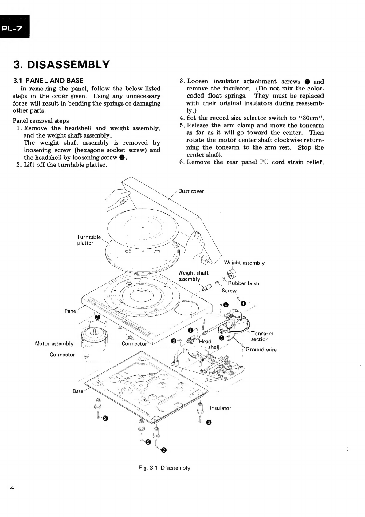
3.
DISASSEMBLY
..
1...
ee
ee
ee
eee
4
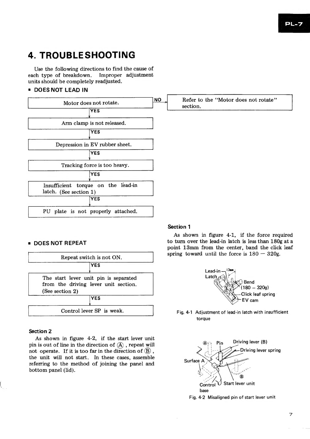
4,
TROUBLESHOOTING..............5008-
7
5,
PRECAUTIONS
FOR
REASSEMBLY........
15
6.
ELECTRICAL
PARTS
LIST..............
18
7,
BLOCK
DIAGRAM...............-400-
20
1.
SPECIFICATIONS
Motor
and
Turntable
DriVE
SYSTEM
<5
eles:
na
see
Dee
ee
ka
ee
a
oS
Direct-drive
MOTOR
22
oie!
edit
ancivtenas
st
tl
end
tern
aca,
Serb
Deteda,
Quartz
PLL
Hall
motor
Turntable
Platter
.........
310mm
diam.
aluminum
alloy
die-cast
SPOOUS?
os
ei
isende
s
seect
scat
a8
a
ered
teestcayh
RE
aye
a
ele
a
33-1/3
and
45rpm
Wow
and
Flutter
..............2.05.
Less
than
0.025%
(WRMS)
Signal-to-Noise
Ratio................
More
than
78dB
(DIN-B)
(with
Pioneer
cartridge
model
PC-3MC)
Tonearm
TYPO
sx
esiyt
Ma
vedle
hie
laee
Static-balance
type,
Straight
pipe
arm
Effective
Arm
Length.
..........
0.002000
eee
ee ee
eee
221mm
OVErHANG
Seidink
onto
aces
Sa ee
she
ahha
ehotaw
ele
15.5mm
Usable
Cartridge
Weight................
3g
(min.)
to
8g
(max.)
Subfunctions
Full
auto
mechanism,
Anti-skating
force
control,
Stylus
pressure
direct-readout
counterweight,
Cueing
device,
Strobe
light,
Free
stop
hinges
8.
P.C.
BOARDS
CONNECTION
DIAGRAM
....
21
9.
SCHEMATIC
DIAGRAM
................
23
10.
EXPLODED
VIEWS
................40.
25
11.
ADJUSTMENTS.
.........
0.00000
eee
30
REGIAGE.
oF
cco
hes
eina
bdo
32
AJUS
TE:
ccs
he
eee
te
is
oa
ee
walter
ae
3
34
Miscellaneous
Power
Requirements...
......2.0
2
2
peewee
AC120V,
60Hz
Power
Consumption
.............000
000000
be
ee
Sw
Dimensions
..............
420(W)
X
108(H)
xX
367(D)mm
16-1/2(W)
X
4-1/4(H)
X
14-7/16(D)in.
Weight:
04)
gcse
a
Pie
eee
Ba
aes
5.9kg/13
tb
Accessories
EP
Adapter:
3.25023
ssn
Aiea
fae
es
aa
2
ad
POE
per
et
1
Operating
Instructions...
..
.
ee
1
NOTE:
Specifications
and
design
subject
to
possible
modification
without
notice,
due
to
improvements.