SAFETY INFORMATION ...................... 1
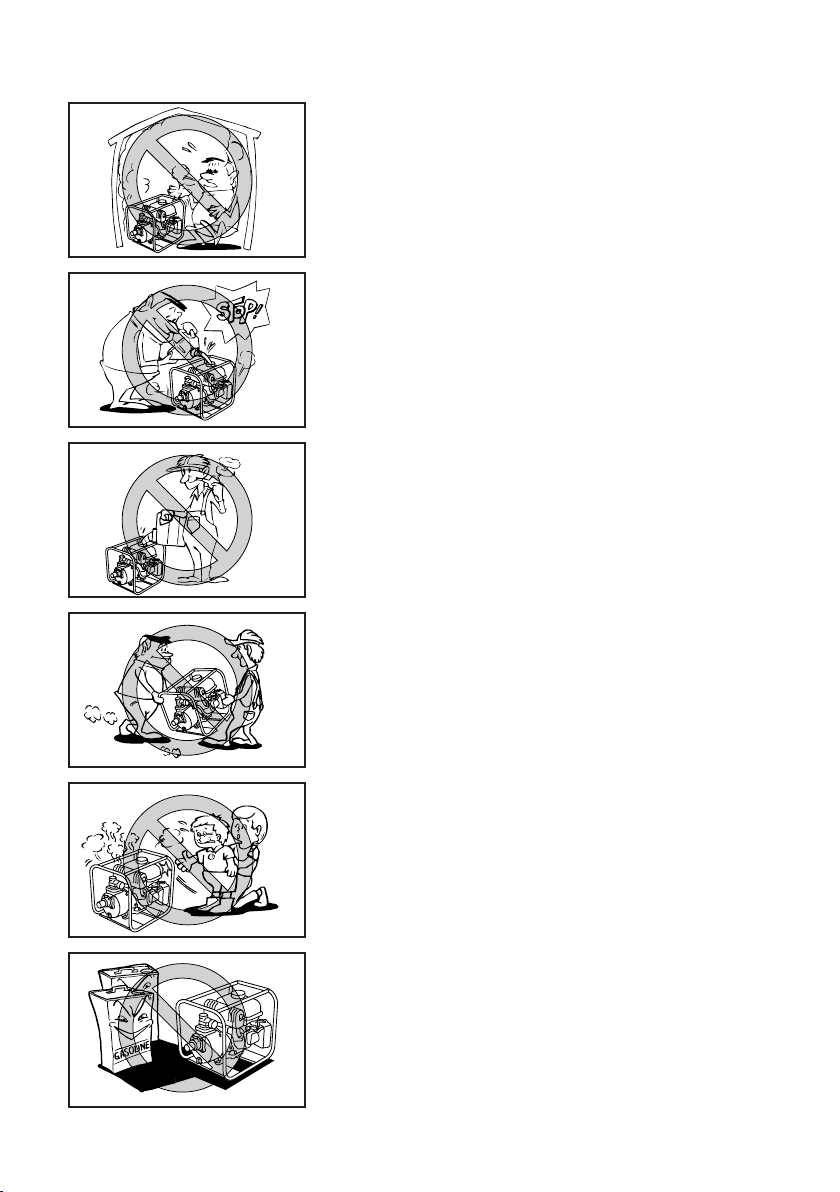
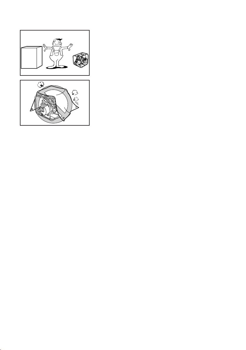
Exhaust fumes are poisonous ............ 1
Fuel is highly flammable and
poisonous ........................................... 1
Engine and muffler may be hot .......... 1
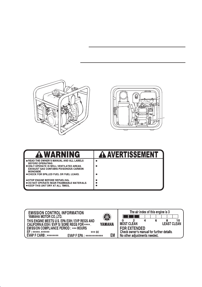
LOCATION OF IMPORTANT
LABELS ................................................ 3
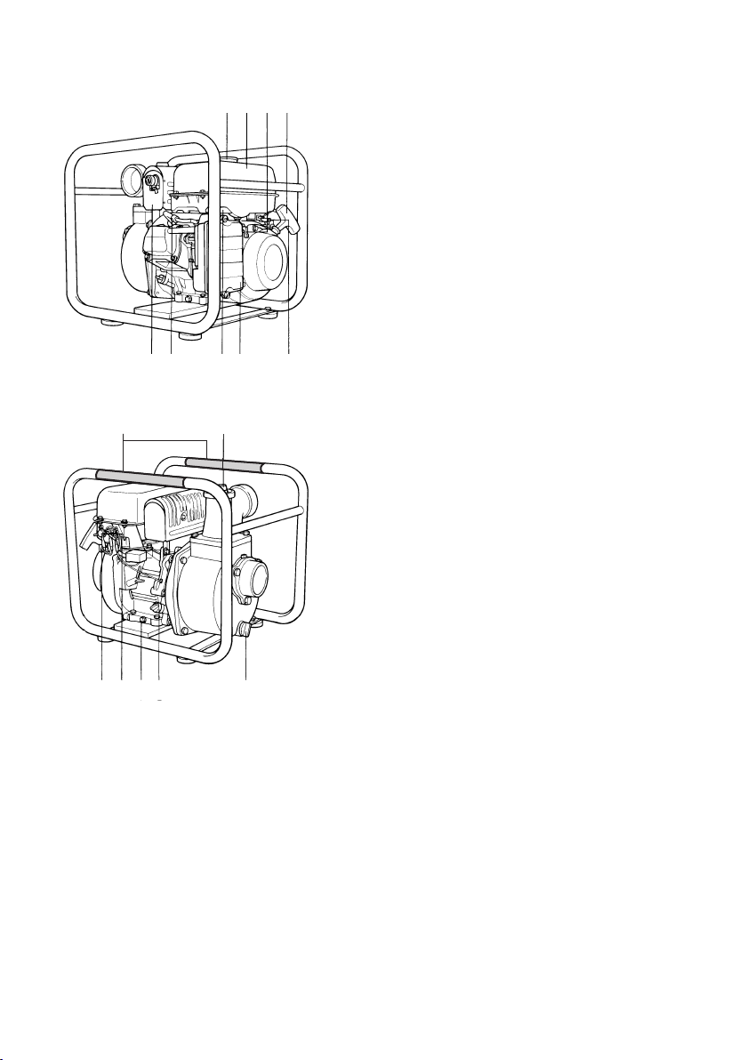
DESCRIPTION ...................................... 4
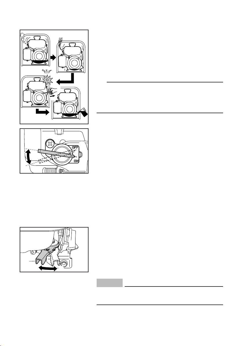
CONTROL FUNCTION ......................... 5
Oil warning light (Red)........................ 5
Engine switch ..................................... 5
Throttle lever ...................................... 5
Fuel cock lever ................................... 6
Choke lever ........................................ 6
Recoil starter ...................................... 6
PREPARATION ..................................... 7
Fuel .................................................... 7
Engine oil ........................................... 8
Water hose installation ....................... 9
Water priming ................................... 10
PRE-OPERATION CHECK ................. 11
Pre-operation check ......................... 11
OPERATION ....................................... 12
Preparation for operation.................. 12
Water priming ................................... 12
Starting the engine ........................... 13
Stopping the engine ......................... 14
Drain water after use ........................ 15
High altitude operation .................... 15
PERIODIC MAINTENANCE ................ 16
Maintenance chart ........................... 16
Spark plug inspection ....................... 17
Carburetor adjustment ..................... 18
Water leakage check ........................ 18
Engine oil replacement ..................... 18
Air filter ............................................. 20
Fuel cock .......................................... 21
Fuel tank filter ................................... 22
Muffler screen and spark arrester .... 22
Troubleshooting ................................ 24
STORAGE ........................................... 27
Drain the fuel .................................... 27
Engine .............................................. 29
SPECIFICATIONS ............................... 30
Dimensions ...................................... 30
Engine .............................................. 30
Pump ................................................ 30
CONSUMER INFORMATION.............. 31
Identification number records ........... 31
Machine identification ....................... 31
EXHAUST EMISSION CONTROL
SYSTEM AND COMPONENTS .......... 32
WIRING DIAGRAM ............................. 33
RUBBER MOUNT INSTALLATION .... 34
CONTENTS
9CB-F8199-70-E0.indd 3 2015/02/11 9:20:26