-8-
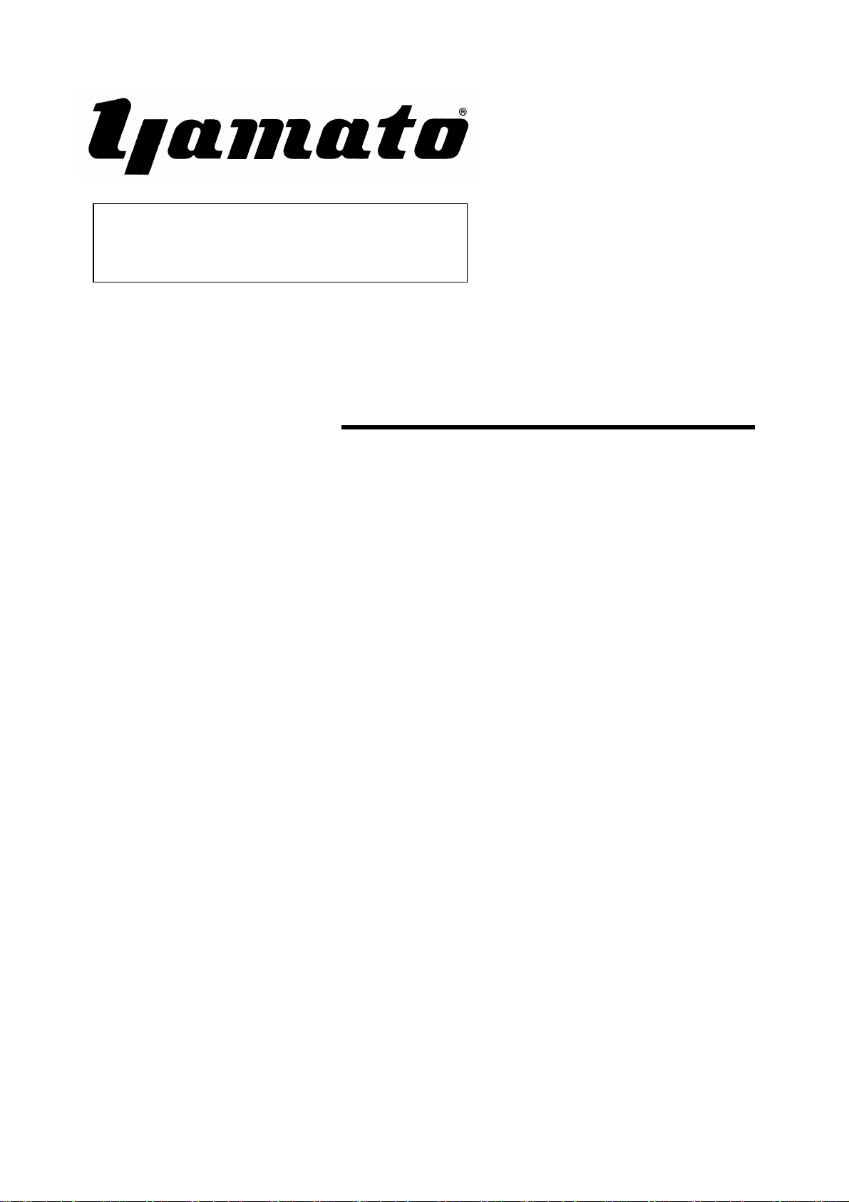
5-6 Adjusting Differential Feed
Normal differential feed or reverse differential feed can
be set freely by turning Knob①.
As differential feed and main feed is driven individually,
when main feed amount (stitch length) is changed, the
differential ratio changes accordingly.
In this case readjustment is necessary.
The graduation shows the amount of differential feed.
For instance, in case the desired feed amount (stitch
length) is "2" and if the graduation is set at "2" by turning
Knob①, the differential ratio becomes 1:1.
When setting the graduation over "2", it becomes norma l
differential and setting it under "2", it becomes reverse
differential.
For the main feed amount the upper limit is "4".
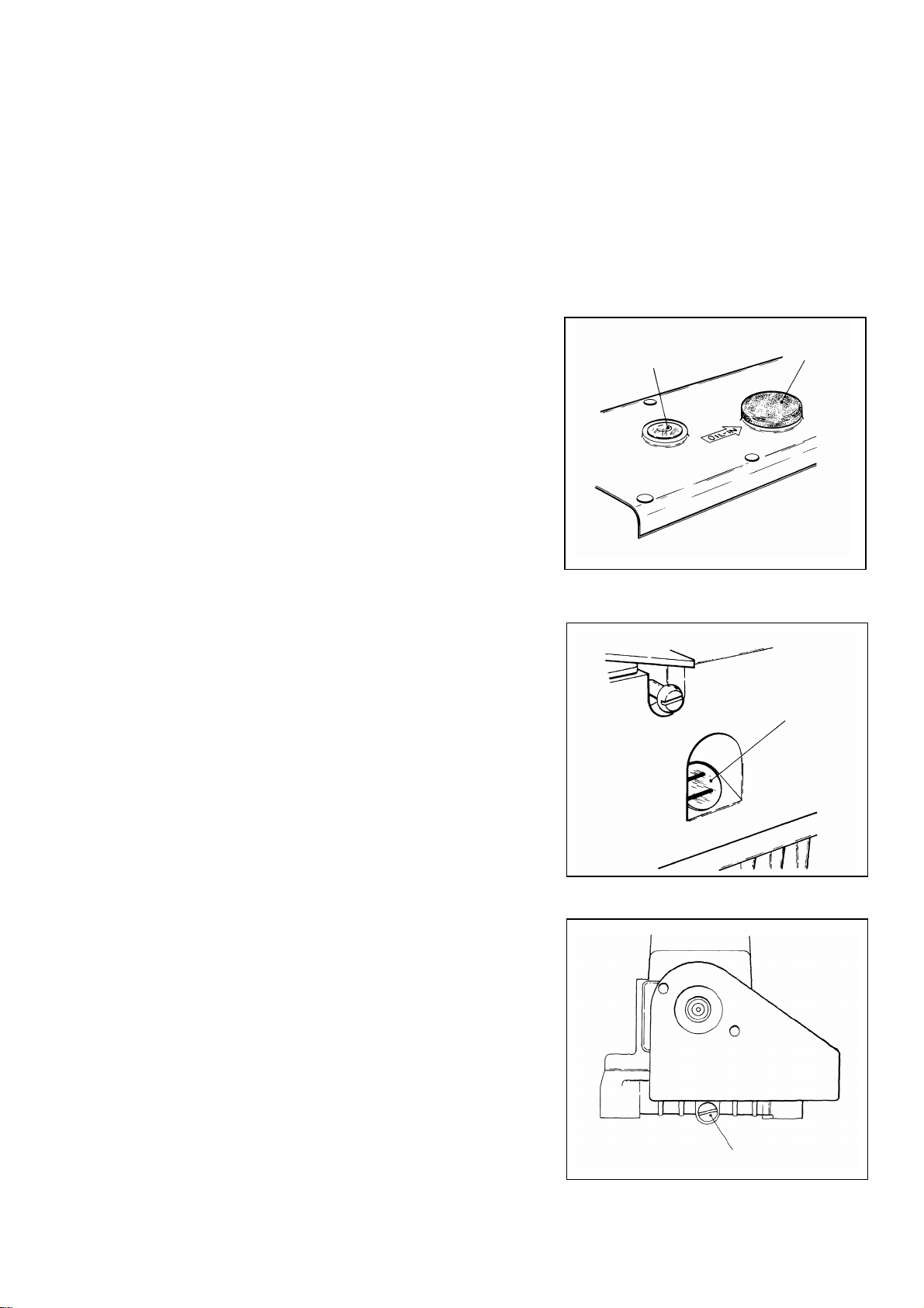
✽When using Differential Feed Control Lever Fix
Differential Feed Control Lever at the desired position
with Nut ③ within the range from the position of
graduation on Lever when turning Knob① to Stopper
②.
At the time of using max. differential feed, turn Knob
① and set Lever at graduation "1".
For adjusting feed amount during operation, attach a
chain to the Lever.
※The range of differential ratio varies according to the
stitch length. Refer to the table below:
stitch length max. normal
differential
max.
reverse
differential
3.6㎜ 1:1.1 1:0.3
2.5㎜ 1:1.6 1:0.4
2.0㎜ 1:2 1:0.5
1.4㎜ 1:2.9 1:0.7
①
②③