Yamato CF800 User manual

Neo-cool Circulator
Model CF800
Instruction Manual
- Second Edition -
Yamato Scientific America Inc.
Santa Clara,CA
This paper has been printed on recycled paper
Thank you for purchasing " Neo-cool Circulator,
CF 800" of Yamato Scientific Co., Ltd.
To use this unit properly, read this "Instruction
Manual" thoroughly before using this unit.
Keep this instruction manual around this unit for
referring at anytime.
WARNING!:
Carefully read and thoroughly understand the
important warning items described in this manual
before using this unit.


Contents
Cautions in Using with Safety ...................................................................1
Explanation..................................................................................................................1
Table of Illustrated Symbols .........................................................................................2
Fundamental Matters of “WARNING!” and “CAUTION!” ...............................................3
Before Using this unit ................................................................................5
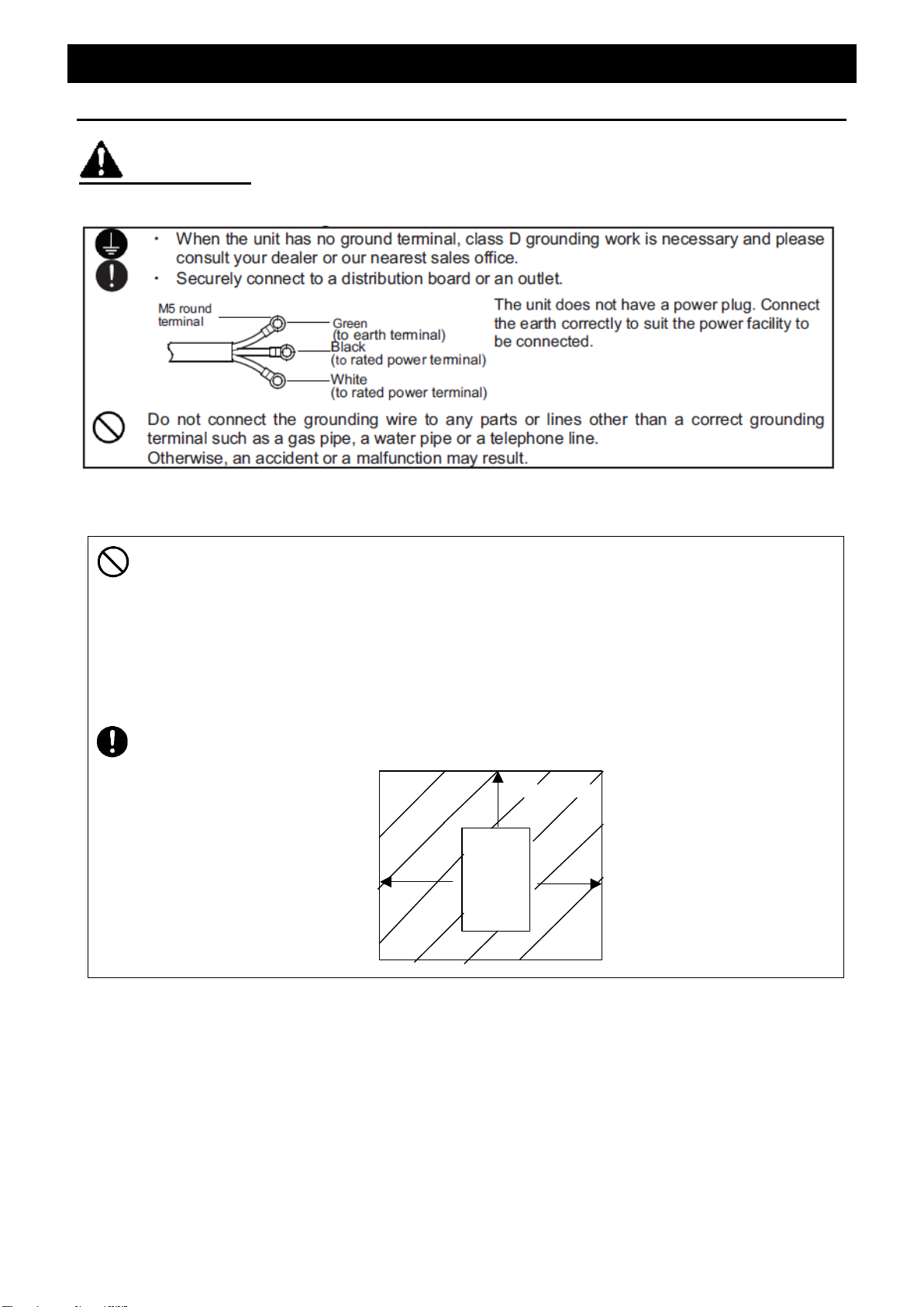
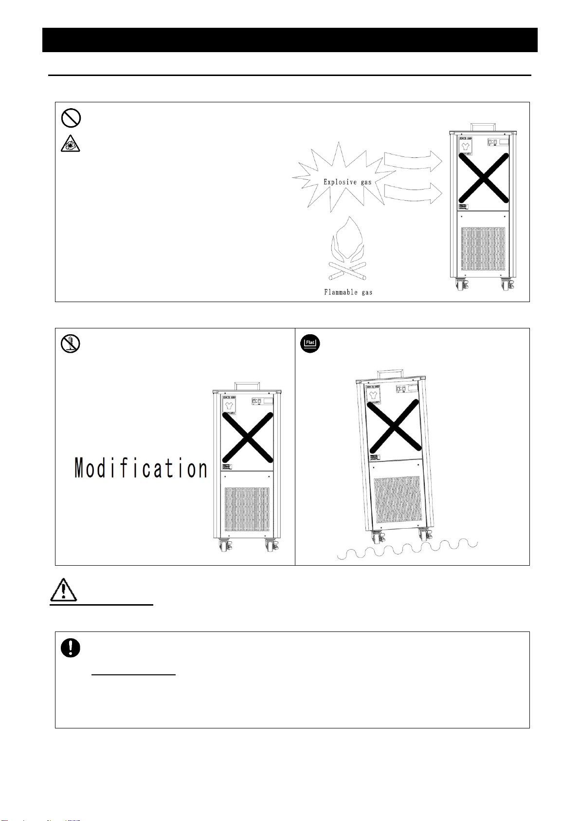
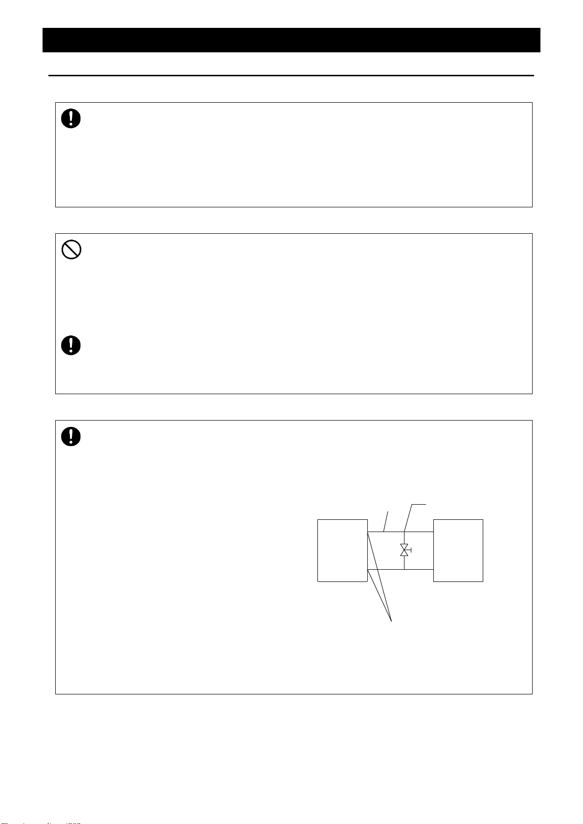
Requirements for Installation........................................................................................5
Description and Function of Each Part...................................................10
Main Unit and Control panel.......................................................................................10
Installation Method...................................................................................12
Operation Method.....................................................................................14
Procedure of Operation..............................................................................................14
Heating and cooling curve, cooling capacity curve (reference data)...........................15
Flow Rate and Head (reference data)........................................................................16
Selecting heat medium for lower temperature (reference data)..................................17
Handling Precautions...............................................................................18
Maintenance Method................................................................................21
Daily Inspection and Maintenance..............................................................................21
Long storage and disposal......................................................................23
When not using this unit for long term / When disposing............................................23
Notes about disposition..............................................................................................23
In the Event of Failure…...........................................................................24
After Service and Warranty......................................................................25
Specification.............................................................................................26
Wiring Diagram.........................................................................................27
Replacement Parts Table .........................................................................28
Reference..................................................................................................29
List of Dangerous Substances ...................................................................................29
Standard installation manual...................................................................30

1
Cautions in Using with Safety
Explanation
MEANING OF ILLUSTRATED SYMBOLS
Varioussymbolsare used in this safety manual in order to use the unit without
danger of injury and damage of the unit. A list of problems caused by ignoring
the warningsand improper handling is divided as shown below.Be sure that you
understand the warnings and cautions in thismanual before operating the unit.
WARNING! If the warning is ignored, there is the danger of a problem that
may cause a serious accident or even fatality.
CAUTION! If the caution is ignored, there is the danger of a problem that may
cause injury/damage to property or the unit itself.
Meaning of Symbols
This symbol indicates items that urge the warning (including the caution).
A detailed warning message is shown adjacent to the symbol.
This symbol indicates items that are strictly prohibited.
A detailed message is shown adjacent to the symbol with specific actions not to
perform.
This symbol indicates items that should be always performed.
A detailed message with instructions is shown adjacent to the symbol.
Illustrated Symbols

2
Cautions in Using with Safety
Table of Illustrated Symbols
Warning
Warning,
generally
Warning,
high voltage
Warning,
high temperature
Warning,
drive train
Warning,
explosive
Caution
Caution,
generally
Caution,
electrical shock
Caution,
scald
Caution,
no road heating
Caution,
not to drench
Caution,
water only
Caution,
deadly poison
Prohibit
Prohibit,
generally
Prohibit,
inflammable
Prohibit,
to disassemble
Prohibit,
to touch
Compulsion
Compulsion,
generally
Compulsion,
connect to the
grounding
terminal
Compulsion,
install on a flat
surface
Compulsion,
disconnectthe
powerplug
Compulsion,
periodical
inspection

3
Cautions in Using with Safety
Fundamental Matters of “WARNING!”and “CAUTION!”
WARNING!
Do not use this unit in an area where there is flammable or explosive gas
Never use this unit in an area where there is flammable or explosive gas.
This unit is not explosion-proof. An arc may be generated when the power switch is turned on or off,
and fire/explosion may result. (Refer to page29 “List of Dangerous Substances”.)
Always ground this unit
Always ground this unit on the power equipment side in order to avoid electrical shock due to a power
surge.
If a problem occurs
If smoke or strange odor should come out of this unit for some reason, turn off the power key right away,
and then turn off the circuit breaker and the main power. Immediately contact a service technician for
inspection. If this procedure is not followed, fire or electrical shock may result. Never perform repair work
yourself, since it is dangerous and not recommended.
Do not use the power cord if it is bundled or tangled
Do not use the power cord if it is bundled or tangled. If it is used in this manner, it can overheat and
fire may be caused.
Do not process, bend, wring, or stretch the power cord forcibly
Do not process, bend, wring, or stretch the power cord forcibly. Fire or electrical shock may result.
Pay special attention to the measure for flammability
and handling of flammable solvent
Leaving at the temperature higher than the room temperature may vaporize the flammable material
(ethanol, etc.). There might be the case that some flammable liquid might be vaporized at the
temperature lower than the room temperature. The result of such careless handling could cause the
fire or explosion. Do provide the vaporization with enough during the operation.
Never try to touch a hot part.
Some parts of the unit are hot during and immediately after operation. Take special care for possible
burning.
Do not disassemble or modify this unit
Do not disassemble or modify this unit. Fire or electrical shock or failure may be caused.

4
Cautions in Using with Safety
Fundamental Matters of “WARNING!”and “CAUTION!”
CAUTION!
When a thunder is heard
When a thunder is heard, turn the main power off immediately. A malfunction, fire or an electrical shock
may result.
Do not touch the cooling fin with bare hands
Do not touch the cooling fin with bare hands during maintenance, for the edge of the cooling fin is too
sharp to cut your hand.

5
Before Using this unit
Requirements for Installation
WARNING!
1. Be sure to connect the ground wire.
2. Choose a proper place for installation
Do not install this unit in a place where:
Rough or dirty surface.
Flammable gas or corrosive gas is generated.
Ambient temperature bellow 5℃or above 35C.
Ambient temperature fluctuates violently.
There is direct sunlight.
There is excessive humidity and dust.
There is a constant vibration.
Outdoor
Install this unit on a stable place with the space as shown below.
More than
20cm
More than
20cm
Front side
More than 40cm
Main
Unit

6
Before Using this unit
Requirements for Installation
3. Do not use this unit in an area where there is flammable or explosive gas
Never use this unit in an area where
there is flammable or explosive gas.
This unit is not explosion-proof. An arc
may be generated when the power
switch is turned ON or OFF, and
fire/explosion may result.
To know about flammable or explosive
gas refer to page29 “List of Dangerous
Substances”.
4. Do not modify
5. Do not topple or tilt this unit
Modification of this unit is strictly
prohibited. This could cause a failure.
Set this unit to the flattest place. This
unit incorporates the refrigerator. Do
not topple or tilt it.
CAUTION!
6. Use specified receptacle for power source
Choose a correct power distribution board or receptacle that meets the unit’s rated electric
capacity.
Electric capacity:
220V AC, 50/60Hz, 7A(I include service power outlet AC100V 5A)
NOTE)
Starburst connection with a branching receptacle or extended wiring with a cord reel lowers
electrical power voltage, which may cause the degradation of refrigeration capability.

7
Before Using this unit
Requirements for Installation
7. Before/after installing
It may cause injure to a person if this unit falls down or moves by the earthquake and the
impact. etc..To prevent, take measures that the unit cannot fall down, and not install to busy
place.
Though this unit has the air-cooled refrigerator, the device exhausts the heat. Do provide
the vaporization with enough so as not to raise the ambient temperature caused by the
exhaust of the heat, or install this unit with its air controlled completely. If the ambient
temperature becomes high, the operation efficiency becomes worse, and could cause the
malfunction of the device by high temperature and humidity.
8. Handling of power code
Do not entangle the power cord. This will cause overheating and possibly a fire.
Do not bend or twist the power cord, or apply excessive tension to it. This may cause a fire
and electrical shock.
Do not lay the power cord under a desk or chair, and do not allow it to be pinched in order to
prevent it from being damaged and to avoid a fire or electrical shock.
Keep the power cord away from any heating equipment such as a room heater. The cord's
insulation may melt and cause a fire or electrical shock.
If the power cord becomes damaged (wiring exposed, breakage, etc.), immediately turn off
the power at the rear of this unit and shut off the main supply power. Then contact your
nearest dealer for replacement of the power cord. Leaving it may cause a fire or electrical
shock.
Connect the power plug to the receptacl which is supplied appropriate power and voltage.
9. Before/after installing
Connect the circulation port of the main
body to the coolant device securely so
as not to leak cooling liquid.
Closing the circulation path with the
solenoid valve or throttle valve might
cause the malfunction of the pump such
as water leakage.
Please open the stop valve discharge
and the return at the time of the pump
driving by all means.
Pay attention to the over-throttle. Keep
minimum flow rate of circulating solution
more than 10% of Pump Max.Flow Rate
according to Specification Table on
page 26.
In case that there are solenoid valve on
the device to be performed the
circulation cooling, or in case that the
flow rate of the device is lower than the
1.5 liter per min. set the bypass circuit
between the main device and peripheral
devices.
Return
Discharge
hose
Bypass Circuit
Connecting Port
(φ
10.5 hose nipple)
External equipment

8
Before Using this unit
Requirements for Installation
10. Secure sufficient ventilation for the unit.
Do not operate the unit when its side panels and vent holes are blocked.
Internal temperature of the unit will rise degrading the performance and an accident, a
malfunction or a fire may result.
11. Do not operate the unit at such a place that may subject to splash.
Do not operate the unit at such a place that may subject to splash. Liquid entering the inside may
cause an accident, a malfunction, an electrical shock or a fire.
12. Do not use liquid other thanwaterand antifreezing liquid (Nybrine®, ethylene glycol)
Pour distilled water or tap water into the water tank. Water of poor quality may cause fur or
scale to accumulate on the heater pump, which may result in deteriorated performance or
malfunction (e.g. well water, etc.).
When you use circulation liquid have a high degree of inflammability such as ethanol, please
perform sufficient ventilation and do not bring close what becomes fire and a source of
ignition by any means.
A circulating liquid with high specific gravity or highly viscosity places overburden on the
circulating pump and damages the unit (e.g. Fluorinert, Galden, etc.).
A corrosive liquid or a liquid that produces corrosive substances when heated may cause
malfunction (e.g. Fluorinate). Also when you mix an antiseptic with an antifreeze solution,
please choose a thing without corrosiveness.(Main parts:Stainless steel plate, Copper,
Nickel plate, Silicon rubber)
Do not use any liquid whose vapor is toxic or hazardous because it may result in an accident
(methyl alcohol, etc.).

9
Before Using this unit
Requirements for Installation
13. Choose circulating liquid according to its operating temperature.
・Choose circulating liquid according to its operating temperature.
TargetTemperaturemorethan10℃: CityWater(orsoftenIndustrialWater)
Target Temperature less than 10℃: Nonfreezing Solution(recommend Naiburain solution diluted by
CityWater)
※Never choose pure water and/or deionized water as circulating liquid.
Make the line up of concentration adjusted Naiburain solution so called Luck-rack Solution as
Yamato Products.
Please contact with local dealer or Yamato sales office and ask for Luck-rack Solution.
May cause failure of this Equipment/Unit so that pay attention to notices below.
・May degrade the concentration percentage of nonfreezing solution for many months operation.
Check concentration percentage of nonfreezing solution and/or change the whole quantity of
nonfreezing solution by every 6(six) months as the standard.
・Change the whole quantity of city water by every 3(three) months as the standard.
・Never choose disqualified water(such as well water etc.), or pure water and deionized water as
circulating liquid.
・May not meet with the Equipment/Unit performance because circulating pump will be
overworked, if apply high specific gravity and/or high viscosity liquid such as Fluorinert(by 3M)
and GALDEN(by Daitoku Tech) etc.
・Never apply following solution to this Equipment/Unit.
1) Corrosive solution, and /or
2) Solution to generate corrosives at heating such as Fluorinert(by 3M) etc.
3) Solution to be harmed human body by absorbing its evaporating gas such as methanol
Check component materials to contact with solution below, choose adequate disinfectant, mix
it with circulating solution, and then apply.
(Component materials to contact with solution:
Stainless Steel, Copper w/nickel plated, Silicon Rubber)
・Be careful flammable solution to apply as nonfreezing solution such as ethanol, etc.
1) Ventilate laboratory/room well.
2) Never bring fire and igniting source(static electricity etc.) close to this Equipment/Unit.
Product Name
Product
Code
Concentration
(Wt%)
STD Target
Temperatur
e
Package Volume
( in litters)
Luck-rack
Solution: Z16005
756071
60
-20
5L
Luck-rack
Solution: Z16010
756072
10L
Luck-rack
Solution: Z10005
756073
100
-30
5L
Luck-rack
Solution: Z10010
756074
10L
Luck-rack
Solution: NFP6005
756075
60
-10
5L
Luck-rack
Solution: NFP6010
756076
10L

10
Description and Function of Each Part
Main Unit and Control panel
Cas
ter
(Tw
o
front
cast
ers
hav
e
stop
per)
Service electrical
outlet (AC100V 5A)
Discharge Port
(With a nipple
φ10.5mm)
Return Port
(With a nippleφ10.5mm)
Air Intake Filter
Temperature Control Panel
Pump Switch
Caster
(Two front casters have stopper)
Refrigerator Switch
Power Switch
(ELB)
Power Cord
Without plug
Tank cover
Overflow Port (With a
nipple, φ9~10mm)
Drain Cock
(With a nipple,
φ10.5mm)

11
Description and Function of Each Part
Main Unit and Control panel
Part Name
Function
Power switch (Earth Leakage Breaker):
This is the power switch Turns ON/OFF the main power.
Temperature controller:
Controls the temperature of cooling liquid in the bath.
(Range: -20 to 30℃)
Refrigerator switch:
Turns ON/OFF the refrigerator.
Pump switch:
Turns ON/OFF the circulation pump.
Power Switch
(ELB)
Power Cord
Without plug
Pum
p
swit
ch
Refrig
erator
ON
PUMP

12
Installation Method
1. Unlock the stopper of the caster.
Pulling up the lever of the stopper for
caster releases the lock.
(Only the two casters in front of the unit are
attached the stopped.)
2. Move the device tothe place tobe installed.
If there is a step on the floor, the too strong
impact is given to the caster, and could
give the damage. In that case, move the
device by lifting at the step.
3. When the installation place is determined,
pull down the lever of the stopped for
caster, and lock them.
4. Check that the drain cock valve is set at the
“CLOSE”position.
Cover opened status
Close
Drain cock
Overflow
Open
Drain cock
valve
REFRIGE
Temperature c
ontroller
Caster
Stoppe
r
Draining position
Operating

13
Installation Method
5. Power Plug Connection
Check the earth leakage breaker, the refrigerator switch and the pump switch are turned "OFF", and
plug the power cord in the receptacle.
6. Insert the cooling liquid into the bath
Remove the cover of the bath, and insert the antifreezingliquidinto the bath with its cooling coil hidden.
When supplying the liquid, remove the cap of the overflow on the left side surface of the bath without
fail, and prepare the pan for the bath.
With this status, turn on the pump switch, and circulate the liquid. At this time, check that the liquid
is circulated with no abnormal noise. There would be the case that the liquid is not circulated
because of the remained air in the bath. Turn on and off the pump switch for several times for
evacuating the remained air. After completing the evacuation of the remained air, the liquid might be
circulated. Even though the liquid is not circulated yet,turn off the power of therefrigerator and pump
switch immediately, check the status of the relevant devices referring to Page 24 "In the Event of
Failure…". (Keeping the operation of the device without circulating the liquid could cause the
malfunction of the circulation pump.)
After stabilizing the liquid circulation, supply the liquid up to the position where the cooling coil is
hidden with the liquid.
After supplying the liquid, turn OFF the power.
Cover the bath.
7. Connection of the overflow hose
I prepare a bat of around 3L separately, and please install it to prevent circulation liquid from
overflowing from a water tank by the afflux from the outside connection device at the time of the
shutdown.
Overflow
Drain Cock
Bat

14
Operation Method
Procedure of Operation
1. Turn "ON" the earth leakage breaker.
2. Set the temperature.
Set the temperature to be applied with the ”SEL”
key. Pressing the “SEL”key lights on the SV
indicating lamp. Set the temperature with “▲,▼”
keys,andpress the “SEL”keyagainafterchecking
the setting status of the temperature.
3. Turning on switch of the refrigerator.
After checking the C1 lamp of the temperature
controller (control output 1) is turned ON, turn on the
switch of the refrigerator.
The device starts operation by the actuation of the
time after passing about 3 minutes.
Note:
The lighting on and off status of the “C1” lamp of the
temperature controller indicates the performance status
of the output contacting point.
Since the actual control temperature is controlled by the
“ON” and “OFF” of the refrigerator, the time delay
between the “C1” lamp motion of the temperature
controller and “ON” “OFF” timing of the refrigerator might
be occurred. This time delay might be caused by the
pre-setting of the 3-minute delay circuit for preventing
from the refrigerator malfunction.
4. Turning on the pump switch.
Check that the hose is connected between the
circulation port of the main device and cooling device,
and that the circulation liquid is filled into the water
bath. Then turn on the pump switch.
Please open the stop valve discharge and the return
at the time of the pump driving by all means.
5. End of the operation.
Turn off the pump, refrigerator switch, and main power
switch.
ON
SEL
SV
C1
ポンプ 冷凍機
切
入
SEL
ポンプ 冷凍機
切
入
SEL
Drain
cock
Bat
PU
MP
REFRIG
E
ON
OFF
PU
MP

15
Operation Method
Heating and cooling curve, cooling capacity curve (reference data)
Regard the data below as reference only because actual result will differ depending on the
amount of samples and the environmental temperature.
Measurement conditions(cooling characteristics, freezing retaining capacity)
・Room temp:20・External load:no load ・Power supply:AC100V
・Frequency:50Hz(cooling characteristics, cooling capacity), 50Hz/60Hz(flow and lift)
・Circulating liquid:Nybrine 60%
・Circulating liquid amount: 14ℓ
・Fixed position: center in the bath
・Lift Calculated as 1.0MPa =10.0kg/cm2≒100.0m
Cooling characteristics
-25
-20
-15
-10
-5
0
5
10
15
20
25
30
010 20 30 40 50 60 70 80 90 100
Elapsed time(min)
Cooling capacity
0
200
400
600
800
1000
1200
1400
-30 -20 -10 010 20 30

16
Operation Method
Flow Rate and Head (reference data)
0
2
4
6
8
10
12
14
16
0.0 2.0 4.0 6.0 8.0 10.0 12.0
AC100V 50Hz
AC100V 60Hz
0
2
4
6
8
10
12
14
16
0.0 2.0 4.0 6.0 8.0 10.0 12.0
AC100V 50Hz
AC100V 60Hz

17
Operation Method
Selecting heat medium for lower temperature (reference data)
You need to use a heat medium for lower temperature when the cooling temperature is set to 10or below.
Choose Naiburain® product and its concentration according to 10℃lower than working temperature.
Ethylene glycol
Property
Boiling point
197.8
Coagulation
point
-13.0
Ignition point
121.0
Firing point
410.0
SG(at 20)
1.1188
SH(at 20)
0.561cal/g
Evaporative
latent heat
191cal/g
Viscosity
0.021Pa・s(20.93CP)
Steam
pressure(25)
16.0Pa(0.12mHg)
Ethyl alcohol
Property
Molecular weight
46.068
Boiling point
78.32
Coagulation
point
-114.5
Ignition point
13(closed), 18(open)
24.7(60% solution,at25)
Firing point
439
SG(at20)
0.7893
SH(at20)
0.579cal/g・
Viscosity
1.0826cp(at25)
Nybrine
Property
Z1,Z1-K
RH
NFP
50Wt%
100 Wt%
50Wt%
100 Wt%
50Wt%
100 Wt%
Boiling point ()
104
117
105
118
102
107
Specific resistance (Ω・cm at
25)
625
1250
270
440
530
970
Conductivity(S・m-1 at 25)
0.160
0.080
0.370
0.227
0.189
0.103
Steam pressure (KPa at 20)
1.7
0.5
1.7
0.5
2.3
1.3
Freezing point ()
-21
-50 or
less
-21
-50 or
less
-13.5
-50 or
less
SG (at20)
1.05
1.10
1.07
1.134
1.026
1.048
Viscosity (mPa・s at 20)
2.5
9.5
2.5
9.5
2.6
9.4
SH (cal/g at 20)
0.850
0.670
0.850
0.670
0.773
0.642
Freezing temp of ethylene glycol
Freezing temp of Nybrine
F
r
e
e
Fre
ezi
ng
tem
per
0
-10
-20
-30
-
4
0
-50
0
10
20
30
40
50
60
70
80
90
100
0
-10
-20
-30
-40
-50
Nybrine
density
wt
Freezing
temperature
℃
Usable range
Volume concentration (%)
Temperature ()
ON
OFF
REFRIGE
Table of contents
Other Yamato Water System manuals
Popular Water System manuals by other brands

WaterGroup
WaterGroup E75TFC-3 Installation, operation and service manual

Happy Frizz
Happy Frizz GIULIETTA user manual

Culligan
Culligan Mark 100 owner's guide

VWR
VWR Avantor G5 instruction manual

Culligan
Culligan Premier Series Installation, operation and service instructions

Diamond H2O
Diamond H2O Element LT Series manual