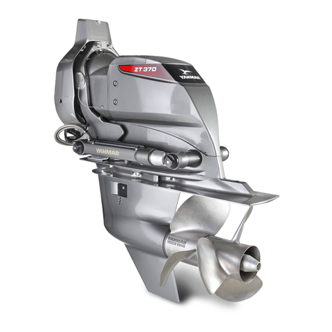
Yanmar ZT350 series User manual

ZT350
series
INSTALLATION MANUAL
ZT350 Installation Manual
P/N: 0FZTD-G00100
STERN-DRIVE

ii ZT350 Installation Manual
© 2007 Yanmar Marine International
Disclaimers:
All information, illustrations and specifications in this manual are based on the latest information available
at the time of publishing. The illustrations used in this manual are intended as representative reference
views only. Moreover, because of our continuous product improvement policy, we may modify information,
illustrations, and / or specifications to explain and / or exemplify a product, service or maintenance
improvement. We reserve the right to make any change at any time.
Yanmar and are registered trademarks of Yanmar Co., Ltd. in Japan, the United States and /
or other countries.
All Rights Reserved:
No part of this publication may be reproduced or used in any form by any means - graphic, electronic, or
mechanical, including photocopying, recording, taping, or information storage and retrieval systems -
without the written permission of Yanmar Marine International.
© 2007 Yanmar Marine International
1107

ZT350 Installation Manual iii
© 2007 Yanmar Marine International
ZT350 Installation Manual
TABLE OF
CONTENTS
Page
Safety.................................................................................................... 1-1
General Information ............................................................................ 2-1
Notice to Vessel OEM & Equipment Installer .................................. 2-2
Sales and Technical Assistance................................................ 2-2
Tightening Torques for Standard Bolts and Nuts ...................... 2-3
Lubricants / Sealants / Adhesives ............................................. 2-3
Special Tools ............................................................................. 2-4
Trim-In Limiter ........................................................................... 2-4
Steering Tie Bar Considerations ..................................................... 2-5
Internal Tie Bar Only.................................................................. 2-5
Internal and External Tie Bar..................................................... 2-5
External Power Steering with an External Tie Bar..................... 2-5
Corrosion Control ............................................................................ 2-5
Shore Power.............................................................................. 2-5
Antifouling Paint......................................................................... 2-6
Painting the Transom and Stern-Drive ...................................... 2-6
Vessel Design...................................................................................... 3-1
Vessel Design Considerations ........................................................ 3-2
Transom Thickness ................................................................... 3-2
Laying Out the Transom Cutout ................................................ 3-2
Vessel Engine Mount Position................................................... 3-2
Selecting an Engine Exhaust System........................................ 3-3

iv ZT350 Installation Manual
© 2007 Yanmar Marine International
Installing Engine and Drive Unit ........................................................ 4-1
Positioning the Drive Unit................................................................ 4-3
Locating the Crankshaft Vertical Centerline - Single
Engine Installation ..................................................................... 4-3
Locating the Crankshaft Vertical Centerline - Dual
Engine Installation ..................................................................... 4-3
Finding the Crankshaft Horizontal Centerline (X-Dimension).... 4-4
Cutting the Vessel Transom ...................................................... 4-6
Checking the Transom Thickness ............................................. 4-7
Installing the Transom Assembly .................................................... 4-8
Connecting the Speedometer Pickup...................................... 4-10
Drive Unit Seawater Pickup..................................................... 4-10
Alternate Seawater Pickup ...................................................... 4-11
Connecting the Inlet Water Hose ............................................ 4-12
Connecting the Oil Reservoir Hose ......................................... 4-13
Installing the Oil Reservoir ...................................................... 4-14
Installing the Shift Plate........................................................... 4-14
Installing the Steering System................................................. 4-15
Connecting the Steering Cables.............................................. 4-18
Installing the Power Trim Pump .............................................. 4-20
Exhaust Options............................................................................ 4-21
Through-the-Propeller Exhaust ............................................... 4-21
Alternate Exhaust System ....................................................... 4-21
Installing the Engine...................................................................... 4-22
Aligning the Engine ................................................................. 4-23
Electrical Connections................................................................... 4-25
Engine Bonding Wire Connection ........................................... 4-25
Trim Position Sender Connection............................................ 4-25
Y-CaPS Controller Connection................................................ 4-25
Hydraulic Connections .................................................................. 4-27
Oil Reservoir............................................................................ 4-27
Power Steering Hoses............................................................. 4-28
Installing the Drive Unit ................................................................. 4-29
Speedometer Connection........................................................ 4-33
Remote Controls ................................................................................. 5-1
Power Trim System......................................................................... 5-2
Control System.......................................................................... 5-2
Pump Location .......................................................................... 5-2
Steering Helm and Cable ................................................................ 5-2
Steering Cable Specifications ................................................... 5-2
Installation of Steering Cable .................................................... 5-4

ZT350 Installation Manual v
12/05
© 2007 Yanmar Marine International
Throttle and Shift Cables................................................................. 5-5
Shift and Throttle Cable Travel.................................................. 5-5
Verify Propeller Rotation with Mechanical Shift System............ 5-5
Shift Cable Installation and Adjustment........................................... 5-6
Setting the Cable Length: .......................................................... 5-6
Install the Drive Unit Shift Cable................................................ 5-6
Troubleshooting Shift Problems ................................................ 5-9
Pre-Delivery ......................................................................................... 6-1
Pre-Delivery Preparation ................................................................. 6-2
Power Steering Fluid ................................................................. 6-2
Battery Connections .................................................................. 6-2
Check the Power Trim Pump Fluid............................................ 6-3
Fill the Power Trim Pump Fluid ................................................. 6-4
Check the Stern-Drive Oil Level ................................................ 6-4
Fill the Stern-Drive with Oil ........................................................ 6-5
Propeller Selection .................................................................... 6-6
General Propeller Installations .................................................. 6-7
Installing the Propellers ............................................................. 6-8
Removing the Propeller ............................................................. 6-9
Test Preparations .................................................................... 6-10
Engine Operation Tests........................................................... 6-10
Out-of-Water Testing............................................................... 6-10
In-Water Testing ...................................................................... 6-11
Drive Unit Operational Tests ................................................... 6-11
Cold Weather (Freezing Temperature), Seasonal and
Extended Storage.................................................................... 6-13

vi ZT350 Installation Manual
© 2007 Yanmar Marine International
This Page Intentionally Left Blank

ZT350 Installation Manual 1-1
© 2007 Yanmar Marine International
ZT350 Installation Manual Section 1
SAFETY
Yanmar considers safety of great importance and
recommends that anyone that comes into close
contact with its products, such as those who install,
operate, maintain or service Yanmar products,
exercise care, common sense and comply with the
safety information in this manual and on the engine
and stern-drive's safety labels. Keep the labels from
becoming dirty or torn and replace them if they are
lost or damaged. Also, if you need to replace a part
that has a label attached to it, make sure you order
the new part and label at the same time.
Indicates a hazardous situation which, if not
avoided, will result in death or serious injury.
Indicates a hazardous situation which, if not
avoided, could result in death or serious injury.
Indicates a hazardous situation which, if not
avoided, could result in minor or moderate
injury.
Indicates a situation which can cause damage to
the engine and stern-drive, personal property
and / or the environment or cause the equipment to
operate improperly.
A
This safety alert symbol appears
with most safety statements. It
means attention, become alert, your
safety is involved! Please read and
abide by the message that follows
the safety alert symbol.

SAFETY
1-2 ZT350 Installation Manual
© 2007 Yanmar Marine International
General Information
There is no substitute for common sense and
careful practices. Improper practices or
carelessness can cause burns, cuts, mutilation,
asphyxiation, other bodily injury or death. This
information contains general safety precautions
and guidelines that must be followed to reduce risk
to personal safety. Special safety precautions are
listed in specific procedures. Read and understand
all of the safety precautions before operation or
performing repairs or maintenance.
The safety messages that follow have DANGER
level hazards. These safety messages describe
a hazardous situation which, if not avoided, will
result in death or serious injury.
NEVER permit anyone to install or
operate the engine or stern-drive
without proper training.
• Read and understand the Operation Manual
information before you install, operate or service
the engine or stern-drive to ensure that you follow
safe operating practices and maintenance
procedures.
• Safety signs and labels are additional reminders
for safe operating and maintenance techniques.
• See your authorized Yanmar marine dealer or
distributor for additional training.
Crush Hazard
ALWAYS use lifting equipment with
sufficient capacity to lift the stern-drive.
NEVER stand under hoisted stern-drive. If the hoist
mechanism fails, the stern-drive will fall on you,
causing serious injury or death.
NEVER support the stern-drive with equipment not
designed to support the weight of the stern-drive
such as wooden pieces, blocks or by only using a
jack.

SAFETY
ZT350 Installation Manual 1-3
12/05
© 2007 Yanmar Marine International
The safety messages that follow have
WARNING level hazards. These safety
messages describe a hazardous situation
which, if not avoided, could result in death or
serious injury.
Explosion Hazard
While the engine is running or the
battery is charging, hydrogen gas is
being produced and can be easily
ignited. Keep the area around the
battery well-ventilated and keep sparks,
open flame and any other form of ignition out of the
area.
Fire Hazard
Undersized wiring systems can cause
an electrical fire.
Sever Hazard
NEVER service the stern-drive while
under tow or if the engine is running at
idle speed. The propeller may rotate
under these circumstances.
If the vessel has more than one engine, NEVER
service a stern-drive if either of the engines are
running. In multi-engine configurations, the
propeller for an engine that is shut down may rotate
if any of the other engines are running.
Rotating parts can cause severe injury or death.
NEVER wear jewelry, unbuttoned cuffs, ties or
loose-fitting clothing, and ALWAYS tie long hair
back when working near moving / rotating parts
such as the flywheel, propeller or PTO shaft. Keep
hands, feet and tools away from all moving parts.
To prevent accidental equipment movement,
NEVER start the engine in gear.
Before starting the engine, ALWAYS make sure that
all bystanders are clear of the area. Keep children
and pets away while the engine is operating.
Always remove any tools or shop rags used during
maintenance from the area before operation.
Stop the engine before you begin to service the
stern-drive and secure the propeller so it will not
turn.
Alcohol and Drug Hazard
NEVER operate the engine while
under the influence of alcohol or drugs
or when feeling ill.
Exposure Hazard
ALWAYS wear personal protective
equipment including appropriate
clothing, gloves, work shoes, eye
and hearing protection as required
by the task at hand.

SAFETY
1-4 ZT350 Installation Manual
© 2007 Yanmar Marine International
Entanglement Hazard
NEVER leave the key in the key switch
when servicing the engine or
stern-drive. Someone may accidentally
start the engine and not realize you are
servicing it.
NEVER operate or service the engine while
wearing a headset to listen to music or the radio
because it will be difficult to hear the warning
signals.
Burn Hazard
Some of the engine and stern-drive
surfaces become very hot during
operation and shortly after shut-down.
Keep hands and other body parts away
from hot surfaces.
Exhaust Hazard
NEVER block windows, vents, or other
means of ventilation if the engine is
operating in an enclosed area. All
internal combustion engines create
carbon monoxide gas during operation and special
precautions are required to avoid carbon monoxide
poisoning.
Electrical Shock Hazard
ALWAYS turn off the battery switch (if
equipped) or disconnect the negative
battery cable before servicing the
equipment.
ALWAYS keep the electrical connectors and
terminals clean. Check the electrical harnesses for
cracks, abrasions, and damaged or corroded
connectors.
The safety messages that follow have CAUTION
level hazards. These safety messages describe
a hazardous situation which, if not avoided,
could result in minor or moderate injury.
Poor Lighting Hazard
Ensure that the work area is adequately
illuminated. ALWAYS install wire cages on portable
safety lamps.
To o l H a z a rd
ALWAYS use tools appropriate for the task at hand
and use the correct size tool for loosening or
tightening machine parts.
Flying Object Hazard
ALWAYS wear eye protection when
servicing the stern-drive or when using
compressed air or high-pressure water.
Dust, flying debris, compressed air,
pressurized water or steam may injure
your eyes.
Slipping and Tripping Hazard
Ensure that adequate floor space is
set aside for servicing stern-drive. The
floor space must be flat and free of
holes.
Keep floor free of dust, mud, spilled liquids and
parts to help prevent slipping and tripping.

SAFETY
ZT350 Installation Manual 1-5
12/05
© 2007 Yanmar Marine International
The safety messages that follow have NOTICE
level hazards.
It is important to perform the daily checks as listed
in this Operation Manual. Periodic maintenance
prevents unexpected downtime, reduces the
number of accidents due to poor engine or
stern-drive performance and can help extend the
life of the engine and stern-drive.
ALWAYS be environmentally
responsible. Follow the guidelines of
the EPA or other governmental
agencies for the proper disposal of
hazardous materials such as
lubrication oil, diesel fuel and engine coolant.
Consult the local authorities or reclamation facility.
NEVER dispose of hazardous materials by
dumping them into a sewer, on the ground or into
ground water or waterways.
Before operating the engine, check stern-drive oil
level.
If the stern-drive oil temperature is too high, stop
engine immediately and check the stern-drive oil
level and check the oil cooler for proper coolant and
water flow. Always tighten components to the
specified torque. Loose parts can cause equipment
damage or cause it to operate improperly.
Only use replacement parts specified. Other
replacement parts may affect warranty coverage.
NEVER attempt to modify the stern-drive’s design
or safety features. Failure to comply may impair the
stern-drive’s safety and performance
characteristics and shorten the stern-drive’s life.
Any alterations to this stern-drive may affect the
warranty coverage of your stern-drive.
NEVER use the stern-drive lifting eye to lift the
engine and stern-drive as an assembly. Use the
engine lifting eyes to lift the engine and stern-drive.
Only use the stern-drive lifting eye to lift the
stern-drive as a separate component.

SAFETY
1-6 ZT350 Installation Manual
© 2007 Yanmar Marine International
This Page Intentionally Left Blank

ZT350 Installation Manual 2-1
© 2007 Yanmar Marine International
ZT350 Installation Manual Section 2
GENERAL
INFORMATION
Page
Notice to Vessel OEM & Equipment Installer .................................. 2-2
Sales and Technical Assistance................................................ 2-2
Lubricants / Sealants / Adhesives ............................................. 2-3
Special Tools ............................................................................. 2-4
Trim-In Limiter ........................................................................... 2-4
Steering Tie Bar Considerations ..................................................... 2-5
Internal Tie Bar Only.................................................................. 2-5
Internal and External Tie Bar..................................................... 2-5
External Power Steering with an External Tie Bar..................... 2-5
Corrosion Control ............................................................................ 2-5
Shore Power.............................................................................. 2-5
Antifouling Paint......................................................................... 2-6
Painting the Transom and Stern-Drive ...................................... 2-6

GENERAL INFORMATION
2-2 ZT350 Installation Manual
Notice to Vessel OEM & Equipment Installer
© 2007 Yanmar Marine International
Before reviewing the General Information section,
review Safety on page 1-1.
NOTICE TO VESSEL OEM &
EQUIPMENT INSTALLER
This Installation Manual contains safety information
designed to:
• Make you aware of the hazards associated with
the installation of the ZT350 stern-drive.
• Inform you of the risk of injury associated with
those hazards.
• Tell you how to avoid or reduce the risk of injury.
• Prior to work, read and understand the section(s)
of this manual that pertain to the job.
• Read and follow all safety warnings.
NOTICE: Indicates critical information or
instructions that are necessary for proper
installation and / or operation.
Note: See the appropriate Yanmar Technical
Manual for application
recommendations.
This Installation Manual has been written and
published by Yanmar Marine International to assist
boat manufacturer's and service personnel when
installing the products described herein.
It is assumed that these personnel are familiar with
the installation procedures for these products, or
like or similar products, manufactured by Yanmar
Marine International. It is also assumed that they
have been trained in the recommended installation
procedures for these products, which includes the
use of mechanics hand tools and any special tools
that might be required.
We could not possibly know of and advise the
marine trade of all conceivable procedures or
methods by which a service might be performed, or
of every possible hazard and / or results of each
procedure or method. We have not undertaken any
such wide evaluation. Therefore, anyone who uses
a procedure or method not described by the
manufacturer must first satisfy himself that neither
his safety, nor the safety of the product, will be
endangered by the installation or servicing
procedure selected.
All information, illustrations and specifications
contained in this manual are based on the latest
production information available at the time of
publication. However, Yanmar Marine International
reserves the right to change, alter or otherwise
improve the product at any time without obligation
or prior notice.
Sales and Technical Assistance
The Yanmar dealer / distributor network is trained to
assist with any sales or technical issues. This
includes application engineering and service
information.
If you have an issue with the application of our
product that cannot be resolved, contact your
Yanmar Distributor Service Engineer. All requests
for assistance should be directed to your local
Yanmar distributor. The distributor for your area can
be found by using the service locator on the
Yanmar website (www.yanmarmarine.com) or by
contacting Yanmar Marine International.

GENERAL INFORMATION
ZT350 Installation Manual 2-3
Notice to Vessel OEM & Equipment Installer
12/05
© 2007 Yanmar Marine International
Tightening Torques for Standard Bolts and Nuts
Note: Securely tighten all of the fasteners not listed below.
Lubricants / Sealants / Adhesives
Description N·m lb-in. lb-ft
Transom Plate Bolt 45 — 33
Connector Bolt (Seawater) 6 53 —
Plate Bolt (Seawater Inlet) 6 53 —
Exhaust Block-Off Plate Bolt 30 — 22
Steering System Upper and Lower
Pivot Bolt 35 — 26
Steering Cable Coupler Nut 45 — 33
Rear Engine Mount Bolt 45 — 33
Stern Drive Unit Fastener 60 — 44
Propeller Locknut Front 135 — 99
Rear 80 — 59
Propeller Shaft Anode Screw 30 — 22
Description Where Used Part Number
UREA Grease
Water Resistant Type NLGI #2
Ex) Rykon Premium Grease EP
Power Steering Bushings
Obtain Locally
Upper and Lower Pivot Bolts
Clevis Pin
Steering Cable End
Propeller Shaft Splines
Steering Cable and Clevis
Liquid Type Neoprene or
Silicon Sealant
Electrical Connections
Y-CaPS Connections
Multipurpose Heavy-Duty Type Lithium
Grease
NLGI #2
Ex) Valvoline Multipurpose
Grease / GM
Drive Unit Pilot
Universal Joint Shaft O-Rings
Drive Shaft Splines
Coupler Splines
SAE 30W Engine Oil Shift Cable Pivot Points
GL5 Hypoid Gear Oil Oil Reservoir
Lithium Grease
with PTFE
Ex) Cortec Co. Lithium EP Grease with PTFE
Bell Housing Studs
O-Ring Seals
Anchor Pin Threads
Shift Cable
UREA Grease
Water Resistant
Type NLGI #2
Ex) Rykon Premium Grease EP
Unit Bearing (Gimbal Housing)
Dexron III
Automatic Transmission Fluid
Power Steering Pump
Power Trim Pump

GENERAL INFORMATION
2-4 ZT350 Installation Manual
Notice to Vessel OEM & Equipment Installer
© 2007 Yanmar Marine International
Special Tools
Trim-In Limiter
WARNING! Only qualified personnel should
install and evaluate the effectiveness of the
Trim-In limiter. The vessel is required to be
tested at trim-in range and several different
speed settings. If an undesirable handling
characteristic occurs when the drive unit is
trimmed in at higher speeds, the trim-in range
should be adjusted by using a Trim-in limiter.
Wider trim-in ranges and higher speeds may
cause handling problems on some vessels that
could result in personal injury.
The stern-lift will cause certain vessels
(predominantly heavy, deep-V hulls) to list towards
the port or starboard side during full power speeds
with the stern-drive set to full Trim-In. The vessel
will not roll over completely, but the list can often be
significant enough to unseat the operator and / or
passengers. This creates an unsafe situation.
This condition is primarily a result of vessel design
and can only be reduced with thorough
performance testing by the manufacturer (OEM) of
the vessel. However, shifting hull weight to the stern
may be helpful in controlling this tendency.
To help reduce the effect of stern-lift, a Trim-In
limiter is available for the Yanmar ZT350
stern-drive, as a service part.
The Trim-In limiter reduces stern-lift by preventing
the stern-drive unit from reaching the last few
degrees of full trim under. While this device should
reduce the rolling tendency, it may not eliminate the
tendency entirely. The use of a Trim-In limiter, and
the evaluation of its effectiveness, can only be
determined by trial and error adjustments and is
ultimately the responsibility of the boat
manufacturer.
Transom Cutout and Drill Fixture
(196350-92020)
Use to determine where to cut and drill
the boat’s transom for the stern-drive
installation.
Alignment Shaft
(196350-92010)
Aligns the engine and the drive unit
during installation.
0006039
0006040

GENERAL INFORMATION
ZT350 Installation Manual 2-5
Steering Tie Bar Considerations
12/05
© 2007 Yanmar Marine International
STEERING TIE BAR
CONSIDERATIONS
NOTICE: The use of multiple stern-drives requires
a careful consideration of the type of steering
system that should be used.
CAUTION! Failure to observe the recommended
tie bar arrangements could result in serious
damage to the steering and / or power trim
system components. This damage could
adversely affect boat control.
Internal Tie Bar Only
This system is recommended for vessels that
operate at speeds up to 50 knots (58 mph).
It is a direct connection between the slave
stern-drive and the stern-drive that is directly
connected to the factory power steering output.
This internal tie bar is available in a variety of
lengths from Yanmar. Contact your Yanmar dealer
or distributor.
Internal and External Tie Bar
This system is recommended for vessels that
operate at speeds from 50 to 60 knots (60 to 70
mph) or for the benefit of reduced steering
backlash.
Usually, external tie bars are attached at the aft
power trim cylinder bosses, but if one drive is
trimmed differently than the other, undue stress on
the system is introduced. For this reason, dual trim
control equipment should be installed to limit the tilt
differential between the two drives to 20°.
NOTICE: When using an internal power steering
system, Yanmar does not recommend the use of an
external tie bar by itself. This can cause excessive
loads on the steering components and may result in
an increase of the play in boat steering.
External Power Steering with an
External Tie Bar
This system is recommended for vessels that
operate at speeds of 70 knots (80 mph) or greater
or for the ultimate in reduced steering backlash.
This system does not use an internal tie bar, but
requires dual trim control equipment. See Internal
and External Tie Bar on page 2-5.
CORROSION CONTROL
It is the boat designer's responsibility and/or the
re-powering engineer's responsibility to design the
proper systems and equipment to control and
reduce the possibility of galvanic corrosion.
To help control the effects of galvanic corrosion,
Yanmar Marine ZT350 stern-drives come with
several anodes and an electronic anticorrosion
system (Y-CaPS) that protect the stern-drive in
moderate corrosive conditions. However, it is
essential that the owner/operator frequently
monitor the anodes for wear, inspect the stern drive
for corrosion and replace the anodes often enough
to provide a sacrificial surface for the electrical
current to attack. Galvanic isolators are also
available from the aftermarket (not supplied by
Yanmar) to block stray current while still providing a
path to ground for dangerous shock currents.
Shore Power
Vessels that are connected to shore power require
additional protection to prevent destructive low
voltage galvanic currents from passing through the
shore power ground wire. A galvanic isolator is
available to block these currents while still providing
a path to ground for dangerous shock currents.
NOTICE: If AC shore power is not isolated from the
boat ground, the Y-CaPS and anodes may be
unable to neutralize the increased galvanic
potential.

GENERAL INFORMATION
2-6 ZT350 Installation Manual
Corrosion Control
© 2007 Yanmar Marine International
Antifouling Paint
NOTICE: Corrosion damage that results from the
improper application of marine paint or antifouling
paint is not covered by the Yanmar limited warranty.
Observe the following precautions when applying
antifouling or marine paint to the transom of the
boat hull.
• NEVER paint the anodes of installed on the
stern-drive.
• NEVER paint the Y-CaPS reference electrode
and / or anode.
• NEVER wash the stern-drive with a high pressure
washer. This could damage the coating on the
reference wire.
• NEVER paint the stern-drive with a material that
contains copper or tin.
• NEVER paint over drain holes, anodes, Y-CaPS
or other items specified by the anode
manufacturer.
Painting the Transom and
Stern-Drive
Corrosion damage that results from improper
application of anti-fouling paint will not be covered
by the warranty.
Anti-fouling paint may be applied to the vessel hull
and the vessel transom.
NOTICE: NEVER paint the anodes or Y-CaPS
electrode. Painting these components will render
them ineffective as galvanic corrosion inhibitors.
NOTICE: Use copper-based paint as anti-fouling
protection for the vessel hull or vessel transom, as
long as it is not prohibited by law in the area where
the vessel will be operated. If using copper- or
tin-based anti-fouling paint, avoid an electrical
interconnection between the Yanmar product,
anodic blocks, or Y-CaPS and the paint by allowing
a minimum of 40 mm (1-1/2 in.) of UNPAINTED
area on the transom of the vessel and around these
items.
Figure 2- 1
Figure 2-1
1 – Painted Vessel Transom
2 – Minimum 40 mm (1-1/2 in.) of unpainted area
around transom assembly.
NOTICE: The drive unit and transom assembly can
be painted with a good quality marine paint or an
anti-fouling paint that does not contain copper or
any other material that could conduct electrical
current. NEVER paint drain holes, anodes, Y-CaPS
or items specified by the vessel manufacturer.
NOTICE: NEVER wash the stern-drive with a
power washer because it can damage the coating
on the reference wire and increase corrosion.
(2)
(1)
0006341

ZT350 Installation Manual 3-1
© 2007 Yanmar Marine International
ZT350 Installation Manual Section 3
VESSEL DESIGN
Page
Vessel Design Considerations ........................................................ 3-2
Transom Thickness ................................................................... 3-2
Laying Out the Transom Cutout ................................................ 3-2
Vessel Engine Mount Position................................................... 3-2
Selecting an Engine Exhaust System........................................ 3-3

VESSEL DESIGN
3-2 ZT350 Installation Manual
Vessel Design Considerations
© 2007 Yanmar Marine International
Before reviewing the Vessel Design Consideration
section, review Safety on page 1-1.
VESSEL DESIGN
CONSIDERATIONS
ALWAYS adhere to all applicable marine
regulations such as the United States Coast
Guard (USCG), European Union-Recreational
Craft Directive (EU-RCD), and so on and the
standards they reference such as the American
Boat and Yacht Council (ABYC), Society of
Automotive Engineers (SAE), International
Standards Organization (ISO), and so on, when
designing and constructing the boat and the
boat components, such as the engine
compartment, fuel delivery system and exhaust
system.
When choosing a vessel that will potentially be
modified for the installation of the ZT350
stern-drive, ensure that the vessel transom meets
the following criteria:
• Transom thickness should be between 51 and 57
mm (2 - 2.25 in.).
• The inner and outer surface of the transom
should be parallel to within 3 mm (0.125 in.).
• The inner surface of the transom is flat to within 3
mm (0.125 in.).
• The outer surface of the transom is flat to within 2
mm (0.075 in.).
• The transom angle is between 10 and 16° (13° is
ideal).
• Ensure that there is enough flat surface area on
the transom to apply the transom plate. This
would be 203 mm (8 in.) on either side of the
center line of the transom.
Figure 3-1
Figure 3-1
1 – Transom Thickness
2 – Transom Angle
3 – Transom plate coverage 203 mm (8.0 in.)
from the center.
4 – Inner Surface
5 – Outer Surface
Transom Thickness
See Checking the Transom Thickness on page 4-7.
Laying Out the Transom Cutout
See Positioning the Drive Unit on page 4-3.
Vessel Engine Mount Position
The engine mount position should allow for a
minimum of 6 mm (0.25 in.) of vertical adjustment
on the front mounts of the engine.
Note: The mounting hardware that is
incorporated with the engine usually
allows for some adjustment. However, it
is good practice to ensure that the
engine mount points that hold the engine
in the vessel are all in parallel planes.
• Tie a string from the front right mount position
and the left rear mount position.
• Tie a string from the left front mount position
and the right rear mount position.
• The strings should touch at the point of
intersection.
(1)
(2)
(4)
(3)(
3)
(5)0006042
Other manuals for ZT350 series
2
Table of contents
Other Yanmar Outboard Motor manuals
Popular Outboard Motor manuals by other brands

SLEIPNER MOTOR AS
SLEIPNER MOTOR AS SIDE-POWER SE-60/185 S2 installation manual

Vetus
Vetus BOW PRO A Series installation instructions

Yamaha
Yamaha F13.5A owner's manual

Mercury
Mercury 10 FOURSTROKE Installation operation maintenance warranty manual

ePropulsion
ePropulsion eLite user manual

Yamaha
Yamaha sx150x owner's manual