Yard force GT A42 User manual

Hotline : 1300 418 640
Monday - Friday : 9.00am to 4.30pm
Saturday: 9.00am to 3.00pm
Email: [email protected]
Model: GT A42
OPERATOR’S MANUAL
PETROL BRUSH CUTTER
WARNING!
Read this manual carefully before using your brush cutter and keep it
in a safe place for future reference.

2
GT A42 OPERATING MANUAL
TABLE OF CONTENTS
WELCOME
Thank you for choosing to buy a YARDFORCE brush cutter.
All our products are manufactured to the highest standards of performance
and safety.
Please read this operator’s manual carefully.
WELCOME ......................................................................2
TABLE OF CONTENTS .................................................2
INTENDED USE .............................................................3
TECHNICAL SPECIFICATIONS ...................................3
PARTS IDENTIFICATION ..............................................4
SCOPE OF DELIVERY ..................................................5
SAFETY INFORMATION ...............................................6
PREPARATION ...............................................................10
OPERATION ...................................................................15
MAINTENANCE ..............................................................19
TROUBLESHOOTING ...................................................20
STORAGE .......................................................................21
WARRANTY ....................................................................22
3
INTENDED USE
TECHNICAL SPECIFICATIONS
This tool is designed for the following applications:
- Brush cutter (when tted with metal circular blade)
The brush cutter is intended to cut weed and climbing plants. Do not use it
for other purposes that it was not intended. Example, never use it for cutting
wood. Never cut objects with a diameter exceeding 13mm.
- Grass trimmer (when tted with nylon line cutting head)
The grass trimmer is intended for trimming grass. Do not use it for other
purposes.
Note: This tool is designed for domestic use. It is not designed for or
warranted for use in commercial, trade or industrial applications.
Model GT A42
Engine Type 2-Stroke Euro V
Displacement 33 cc
Max. Cutting speed 7000 rpm
Rated Power 0.9 kw
Metal Blade size 1.4 x 255 x 25.4 mm
Max. Cutting Capacity Ø 13 mm
Nylon Line Cutting Head (Max. Cut) 420 mm
Nylon LIne size 2 mm
Fuel Capacity 0.7 L
Fuel/Oil Ratio 40:1
Easy Start Yes
Net Weight 8 kg
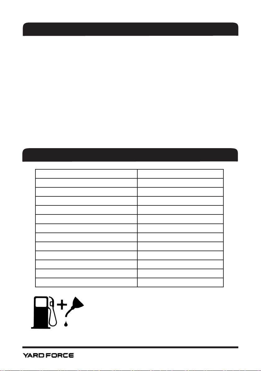
USE FRESH UNLEADED FUEL (PETROL), 90
OCTANE OR BETTER – Do NOT use E10 or
Ethanol blends.
Mix with a premium grade air cooled 2 stroke oil
at a ratio of 40:1
40:1

4
PARTS IDENTIFICATION
1
9
10
11
12
13
14
16
2
4
5
6
7
8
3
1. Spark plug.
2. Starter.
3. Fuel cap.
4. Air lter.
5. Strap attachment point.
6. Left handle.
7. Shaft joint clamp.
8. Guard.
9. Cutting Head.
10. Cutting blade.
11. Right handle.
12. Throttle lever.
13. Throttle lock button.
14. ON /OFF switch.
15. Throttle interlock.
16. Control cable.
15

5
SCOPE OF DELIVERY
A. Engine, upper shaft and
right handle assembly.
B. Lower shaft.
C. Left handle.
D. Guard.
E. Line trimmer spool.
F. Metal cutting blade.
G. Shoulder belt.
H. Bracket for guard.
I. Hex keys,1 x 4mm,
1 x 5mm.
J. Spark plug spanner.
●Remove all packing material.
●Check the completeness of the package content.
●Check the tool and its accessories for transportation damage.
WARNING! Danger of suocating! Packing materials are not toys!
Children must not play with plastic bags!
IF ANY PARTS ARE MISSING OR DAMAGED,
PLEASE CONTACT ACTION SPARES 1300 418 640
Recycle/dispose of packaging materials in accordance to the regulations
and requirements of your local council.
A
B
C
D
J
GH
I
E
F

6
SAFETY INFORMATION
GENERAL
WHEN using the product, a few safety precautions must be observed to avoid
injuries and damage to the product.
READ the operating instructions carefully and comply with them at all times.
KEEP this manual in a safe place so that the information is readily available at
all times.
IF you give the equipment to another person it is important for them to read
the operating instructions prior to use.
DESCRIPTION OF SYMBOLS
Symbols are used in this manual and/or on the product to attract your attention
to possible risks. These symbols and the explanations that accompany them
must be understood.
WARNING! To reduce the risk of injury all users must read the
operator’s manual before using the product.
Risk of ying debris.
Keep bystanders away at least 15 metres.
WARNING! or CAUTION! This symbol before a safety comment
indicates a precaution, warning or danger.
Ignoring these warnings can lead to an accident for yourself or for
others. To limit the risk of injury, re or electrocution always follow the
recommendations indicated.
Wearing eye, ear and head protection.
Do NOT use saw blades.
Wear gloves while using.
Wear sturdy footwear.

7
Australian regulatory compliance mark.
SAFETY INSTRUCTIONS
TRAINING
A. Read the instructions carefully. Get familiar with the controls and
proper use of the tool.
B. Only use the tool for the purpose for which it was designed. Any
other use can be hazardous and may also cause damage to the tool.
C. Never allow children or people unfamiliar with these instructions to
use the tool. Local regulations may restrict the age of the operator.
D. Never use the tool:
• When people, especially children, or pets are nearby.
• If the operator has taken medicine or substances that can
aect his ability to react and concentrate.
E. Remember that the operator or user is responsible for accidents or
hazards occurring to other people or their property.
WARNING! Proper safety precautions must be observed. Like
all power equipment this tool must be handled carefully. DO NOT
EXPOSE YOURSELF OR OTHERS TO DANGER. Follow these
general rules. Do not permit others to use this tool unless they are
trained in its operation.
WARNING! THIS TOOL CAN CAUSE SERIOUS INJURIES. Read
the instructions carefully for the correct handling, preparation,
maintenance, starting and stopping of the tool. Be familiar with all
controls and the proper use of the tool.
GENERAL SAFETY INSTRUCTIONS
A. Never allow children to use the tool.
B. Beware of overhead power lines.
C. Do not use the tool while people or children are nearby. Keep at
least 15 metres away.
D. Dress properly! Do not wear loose clothing or jewellery, which can be
caught in moving parts.
E. Use of sturdy gloves, nonskid footwear hearing protection and safety
glasses.
F. Use extra care when handling fuels. They are ammable and the
vapours are explosive.

8
G. The following points should be observed:
• Use only an approved fuel container.
• Never remove the fuel cap or add fuel with the engine
running.
• Allow engine and exhaust components to cool down before
refuelling.
• Do not smoke.
• Never refuel indoors.
• Never store the tool or fuel container inside where there is an
open ame, such as near a water heater.
• If fuel is spilled, do not attempt to start the engine, move the
tool away from the spillage before starting.
• Always replace and securely tighten the fuel cap after
refuelling.
H. If the tool starts making any unusual noise or vibration. Turn OFF the
engine and allow the tool to stop and take the following steps:
• Inspect for damage:
• Check for and tighten any loose parts;
• Have any damaged parts replaced repaired with parts having
equivalent specications
WHEN USING THE TOOL
A. Stop the engine before:
• Cleaning or when clearing a blockage.
• Checking, carrying out maintenance or working on the tool.
• Adjusting the working position of the cutting device.
• Leaving the tool unattended.
B. Ensure that the tool is correctly located in a designated working
position before starting the engine.
C. While operating the tool always ensure that the operating position is
safe and secure, especially when using steps or a ladder.
D. To reduce re hazards keep the engine and silencer free of debris,
leaves and excessive lubricant.
E. Always ensure that all handles and guards are tted when using the
tool. Never attempt to use an incomplete tool or one tted with an
unauthorised modication.
F. Always be aware of your surroundings and stay alert for possible
hazards of which you may not be aware due to the noise of the tool.
G. Keep fuel in a suitable container specially made for this purpose.

9
WARNING! Dress appropriately.
WARNING! Beware of kickback.
ADDITIONAL SAFETY RULES FOR PETROL BRUSH CUTTER
A. Always use the brush cutter with the shoulder strap.
B. Do NOT use saw blades. Use only blades designed for use with
brush cutters.
C. Do not operate with loose clothing or long hair. These can be sucked
into the air intake of the tool.
D. While using, always wear sturdy footwear and long trousers. Do not
operate the equipment with bare feet or open sandals.
E. Do not operate in a hazardous location. Such areas include where
there is a risk of explosion of fumes, leaking gas or explosive dust.
F. Do not operate in a conned area. Exhaust gases, smoke or fumes
could reach dangerous concentrations.
G. Protect your tool. This tool is NOT WEATHERPROOF and should
not be exposed to direct sunlight, high ambient temperature and
damp, wet or high humidity conditions.
H. Do not smoke or use a mobile phone while refuelling. This is
potentially dangerous as it may ignite the fuel and cause an
explosion.
I. Take care not to spill fuel. When refuelling the tool ensure that the
engine has been switched o. Prevent the spilling of fuel as this
may also ignite with the hot engine. Never refuel whilst the engine is
running.
J. Be careful where you store the tool. Store the tool in a dry area away
from ammable liquids.
K. Keep your distance. The tool emits exhaust fumes.
L. Ensure you use fuel oil mix. Ensure that you mix 40 parts unleaded
fuel to 1 part two stroke oil, if not the engine will overheat and cause
damage to your tool.
M. Never ll fuel tank indoors.
KICKBACK
Take care using the metal blade with the tool. Kickback is a reaction that
occurs when the blade hits objects that it can not cut. This can make the
blade push away from the object or run along the object. This reaction can be
intense enough to lose control of the tool and can occur without a warning.
The operator should cut from right to left to minimize the chance of kickback.

10
N. Never ll fuel tank when engine is running or hot.
O. Stop the engine before re-fuelling.
P. Stop the engine and disconnect the spark plug wire If the tool starts
to vibrate abnormally (nd and remove the cause of the vibration
immediately).
Q. Reduce the throttle before turning o the engine.
R. The user is responsible for the safety of other people, animals and
objects in the working area. Keep people, children and domestic
animals at a safe distance while the tool is in use.
PREPARATION
BEFORE THE BRUSH CUTTER CAN BE USED IT REQUIRES
SOME ASSEMBLY.
INSTALLING THE GUARD
●With the 5 mm Hex key. Remove the
two screws from the top of the guard
and the one on the side of the cutting
head.
● Place the Bracket (H) on the top of the
shaft and reinsert and tighten the screw
in the cutting head.
● Hold the Guard (D) underneath the
bracket, insert the two screws through
the bracket in to the holes in the guard
and retighten rmly.
Table of contents


