YASKAWA L1000A Series User manual

MANUAL NO. SIEP YEUOCL1 01A
CANopen-Lift
Communication Option
Communication Option Card for Lift Inverter
Drive YASKAWA L1000A
Installation Manual
Type: SI-L3

This Page Intentionally Blank
2YASKAWA ELECTRIC SIEP YEUOCL1 01A CANopen-Lift Communication Option Installation Manual

YASKAWA ELECTRIC SIEP YEUOCL1 01A CANopen-Lift Communication Option Installation Manual 3
Table of Contents
1. Preface and General Precautions . . . . . . . . . . . . . . . . . . . . . . . . . . . . . . . . . . 5
Receiving . . . . . . . . . . . . . . . . . . . . . . . . . . . . . . . . . . . . . . . . . . . . . . . . . . . . . . . . . . . . . . . . 5
About Terms and Abbreviations in This Document . . . . . . . . . . . . . . . . . . . . . . . . . . . . . . . 5
About Registered Trademarks. . . . . . . . . . . . . . . . . . . . . . . . . . . . . . . . . . . . . . . . . . . . . . . . 5
Safety . . . . . . . . . . . . . . . . . . . . . . . . . . . . . . . . . . . . . . . . . . . . . . . . . . . . . . . . . . . . . . . . . . . 5
Explanation of Signal Words . . . . . . . . . . . . . . . . . . . . . . . . . . . . . . . . . . . . . . . . . . . . . . . . . 5
General Safety Instructions . . . . . . . . . . . . . . . . . . . . . . . . . . . . . . . . . . . . . . . . . . . . . . . . . . 5
Intended Use . . . . . . . . . . . . . . . . . . . . . . . . . . . . . . . . . . . . . . . . . . . . . . . . . . . . . . . . . . . . . 7
Exclusion of Liability . . . . . . . . . . . . . . . . . . . . . . . . . . . . . . . . . . . . . . . . . . . . . . . . . . . . . . . 7
2. Product Overview . . . . . . . . . . . . . . . . . . . . . . . . . . . . . . . . . . . . . . . . . . . . . . . 7
About This Product . . . . . . . . . . . . . . . . . . . . . . . . . . . . . . . . . . . . . . . . . . . . . . . . . . . . . . . . 7
Applicable Models . . . . . . . . . . . . . . . . . . . . . . . . . . . . . . . . . . . . . . . . . . . . . . . . . . . . . . . . . 8
3. Receiving . . . . . . . . . . . . . . . . . . . . . . . . . . . . . . . . . . . . . . . . . . . . . . . . . . . . . 8
Receiving the Option Card . . . . . . . . . . . . . . . . . . . . . . . . . . . . . . . . . . . . . . . . . . . . . . . . . . 8
Content and Packaging. . . . . . . . . . . . . . . . . . . . . . . . . . . . . . . . . . . . . . . . . . . . . . . . . . . . . 8
Tools Required. . . . . . . . . . . . . . . . . . . . . . . . . . . . . . . . . . . . . . . . . . . . . . . . . . . . . . . . . . . . 8
4. CANopen Lift Option Components . . . . . . . . . . . . . . . . . . . . . . . . . . . . . . . . . 9
CANopen Lift Option SI-L3 . . . . . . . . . . . . . . . . . . . . . . . . . . . . . . . . . . . . . . . . . . . . . . . . . . 9
CANopen-Lift Option Status LEDs . . . . . . . . . . . . . . . . . . . . . . . . . . . . . . . . . . . . . . . . . . . . 9
RUN LED . . . . . . . . . . . . . . . . . . . . . . . . . . . . . . . . . . . . . . . . . . . . . . . . . . . . . . . . . . . . . . . . 9
ERR LED. . . . . . . . . . . . . . . . . . . . . . . . . . . . . . . . . . . . . . . . . . . . . . . . . . . . . . . . . . . . . . . . . 9
Indicator Flash Rates . . . . . . . . . . . . . . . . . . . . . . . . . . . . . . . . . . . . . . . . . . . . . . . . . . . . . . 10
Communication Connector . . . . . . . . . . . . . . . . . . . . . . . . . . . . . . . . . . . . . . . . . . . . . . . . . 10
Communication Cable . . . . . . . . . . . . . . . . . . . . . . . . . . . . . . . . . . . . . . . . . . . . . . . . . . . . . .11
Network Termination . . . . . . . . . . . . . . . . . . . . . . . . . . . . . . . . . . . . . . . . . . . . . . . . . . . . . . .11
5. Mechanical & Electrical Installation. . . . . . . . . . . . . . . . . . . . . . . . . . . . . . . . 12
Safety Precautions . . . . . . . . . . . . . . . . . . . . . . . . . . . . . . . . . . . . . . . . . . . . . . . . . . . . . . . 12
Before Installing the Option Card . . . . . . . . . . . . . . . . . . . . . . . . . . . . . . . . . . . . . . . . . . . . 12
Installing the Option on a L1000A. . . . . . . . . . . . . . . . . . . . . . . . . . . . . . . . . . . . . . . . . . . . 12
EDS File . . . . . . . . . . . . . . . . . . . . . . . . . . . . . . . . . . . . . . . . . . . . . . . . . . . . . . . . . . . . . . . . 14
6. CANopen-Lift Option Related Drive Parameters . . . . . . . . . . . . . . . . . . . . . 14
7. Troubleshooting . . . . . . . . . . . . . . . . . . . . . . . . . . . . . . . . . . . . . . . . . . . . . . . 15
Drive-Side Error Codes . . . . . . . . . . . . . . . . . . . . . . . . . . . . . . . . . . . . . . . . . . . . . . . . . . . . 15
Faults . . . . . . . . . . . . . . . . . . . . . . . . . . . . . . . . . . . . . . . . . . . . . . . . . . . . . . . . . . . . . . . . . . 15
Minor Faults/Alarms . . . . . . . . . . . . . . . . . . . . . . . . . . . . . . . . . . . . . . . . . . . . . . . . . . . . . . 17

4YASKAWA ELECTRIC SIEP YEUOCL1 01A CANopen-Lift Communication Option Installation Manual
8. Specifications . . . . . . . . . . . . . . . . . . . . . . . . . . . . . . . . . . . . . . . . . . . . . . . . . . 17
Revision History. . . . . . . . . . . . . . . . . . . . . . . . . . . . . . . . . . . . . . . . . . . . . . . . . . . 18

1 Preface and General Precautions
YASKAWA ELECTRIC SIEP YEUOCL1 01A CANopen-Lift Communication Option Installation Manual 5
1 Preface and General Precautions
This chapter describes important safety precautions regarding the use of this product. Failure to follow these
precautions may result in serious injury or death, and may lead to damage to this product or related devices and
systems. Yaskawa shall not be held responsible for any injury or equipment damage as a result of failure to
observe the precautions and instructions contained in this manual.
◆Receiving
This instruction manual contains the information necessary to use the product correctly. Thoroughly read this
manual before installing, wiring, operating, or performing maintenance and inspections. Make sure to read and
understand the safety information and precautions before using the product.
■About Terms and Abbreviations in This Document
Representations Used in This
Manual Description
CANopen-Lift Option Yaskawa CANopen Lift communication option card
Online-DRV Processing mode, process (ctrl/resp) data is active
Online-DRVMB Processing mode, process resp data is active, ctrl data is on hold (until MEMOBUS process is
complete)
Online-PRG Processing mode, NO process (ctrl/resp) data is active
Host YASKAWA inverter drive for Lift L1000A
LED Light Emitting Diode
OPT, Option The unit described in this document
INV, Inverter Inverter drive
PCB Printed Circuit Board
FCS Frame Check Sequence
INVR MEMOBUS register number
EDS Electronic Data Sheet file
■About Registered Trademarks
•CANopen® is a registered Community Trademark of CAN in Automation e.V.
•Other company names and product names that appear in this document are trademarks or registered trademarks
of the respective companies.
◆Safety
Read the safety guidelines carefully before installing, wiring, or operating this product.
■Explanation of Signal Words
DANGER Identifies a hazardous situation, which, if not avoided, will cause death or serious injury.
WARNING Identifies a hazardous situation, which, if not avoided, can cause death or serious injury.
CAUTION Identifies a hazardous situation, which, if not avoided, can cause minor or moderate injury.
NOTICE Identifies a property damage message.
■General Safety Instructions
Yaskawa Electric manufactures and supplies electronic components for a variety of industrial applications. The
selection and application of Yaskawa products is the responsibility of the designer of the equipment or the
customer that assembles the final product. Yaskawa is not responsible for how our products are incorporated into
the final system design. In all cases, Yaskawa products should not be incorporated into a product or design as the
exclusive or sole safety control function. All control functions are designed to dynamically detect failures and
operate safely without exception. All products that are designed to incorporate parts manufactured by Yaskawa
must be provided to the end user and include proper warnings and instructions regarding their safe use and

1 Preface and General Precautions
6YASKAWA ELECTRIC SIEP YEUOCL1 01A CANopen-Lift Communication Option Installation Manual
operation. All warnings from Yaskawa must be promptly issued to the end user. Yaskawa offers warranties only
for the quality of our products, in compliance with standards and specifications that are described in the manual.
Yaskawa does not offer other warranties, either explicit or implied. Yaskawa assumes no responsibility for
personal injury, property damage or loss, or compensation for damage caused by the incorrect application of our
products.
Note:
Be aware that serious injury or death may result if the warnings described in this manual are not observed. Yaskawa assumes no
responsibility for injuries or equipment damage to your company or customers that are caused by a failure to observe the information
contained in this manual.
•Read this manual carefully when mounting, operating, and repairing AC drives and Communication options.
•Follow all warnings, cautions, and instructions.
•All work should be carried out by qualified personnel.
•Ensure the drive is installed to an area that matches the following conditions.
DANGER Electrical Shock Hazard. Do not examine, connect, or disconnect wiring on an energized drive. Before
servicing, disconnect all power to the equipment and wait for the time specified on the warning label at a minimum. The internal
capacitor stays charged after the drive is de-energized. The charge indicator LED extinguishes when the DC bus voltage
decreases below 50 Vdc. When all indicators are OFF, remove the covers before measuring for dangerous voltages to make
sure that the drive is safe. Failure to obey will cause death or serious injury.
WARNING Fire Hazard. Do not connect power supply wiring to drive output terminals U/T1, V/T2, and W/T3. Connect
power supply wiring to main circuit input terminals R/L1, S/L2, and T/L3. Failure to obey can cause death or serious injury.
WARNING Electrical Shock Hazard. Do not make changes to the drive body or drive circuitry. Failure to obey can cause
death or serious injury and will void warranty. Yaskawa is not responsible for changes to the product made by the user.
WARNING Electrical Shock Hazard. Only let authorized persons install, wire, maintain, examine, replace parts, and
repair the drive. Failure to obey can cause death or serious injury.
WARNING Electrical Shock Hazard. Always ground the motor-side grounding terminal. Contacting the motor case can
cause death or serious injury from incorrect equipment grounding.
WARNING Electrical Shock Hazard. Do not work on the drive or around the drive while wearing loose clothing or jewelry.
Tighten loose clothing and remove all metal objects such as watches or rings. Failure to obey can cause death or serious injury.
WARNING Electrical Shock Hazard. The leakage current of the drive will be more than 3.5 mA in drive models 2xxxB,
2xxxC, 4002B to 4371B, 4002C to 4371C (with built-in EMC filter turned ON) and 4389 to 4675. The IEC/EN 61800-5-1: 2007
standard specifies that users must wire the power supply to automatically turn off when the protective ground wire disconnects.
Users can also connect a protective ground wire that has a minimum cross-sectional area of 10 mm2(copper wire) or 16 mm2
(aluminum wire). Failure to obey these standards can cause death or serious injury.
WARNING Sudden Movement Hazard. Remove all persons and objects from the area around the drive, motor, and load
before starting Auto-Tuning. The drive and motor can start suddenly during Auto-Tuning and cause death or serious injury.
WARNING Sudden Movement Hazard. Remove all persons and objects from the area around the drive, motor, and
machine area and attach covers, couplings, shaft keys, and machine loads before energizing the drive. Failure to obey can
cause death or serious injury.
WARNING Fire Hazard. Do not use the main circuit power supply (Overcurrent Category III) at incorrect voltages. Make
sure that the drive rated voltage aligns with the power supply voltage before energizing the drive. Failure to obey can cause
death or serious injury.
WARNING Fire Hazard. Do not put flammable or combustible materials on top of the drive and do not install the drive
near flammable or combustible materials. Attach the drive to metal or other noncombustible material. Failure to obey can cause
death or serious injury.
WARNING Fire Hazard. Tighten all terminal screws to the correct tightening torque. Connections that are too loose or too
tight can cause incorrect operation and damage to the drive. Incorrect connections can also cause death or serious injury from
fire.
WARNING Electrical Shock Hazard. Do not cause a short circuit on the drive output circuit. Failure to obey can cause
death or serious injury.
WARNING Electrical Shock Hazard. Always use a type B Residual Current Monitor/Residual Current Device (RCM/RCD)
where a residual current operated protective or monitoring device protects against direct or indirect contact as specified by IEC/
EN 60755 The drive can cause a residual current with a DC component in the protective earthing conductor. Failure to obey can
cause death or serious injury.
WARNING Electrical Shock Hazard. Ground the neutral point on the power supply of drive models 2xxxB/C and 4xxxA/B/
C to comply with the EMC Directive before turning on the EMC filter or if there is high resistance grounding. If the EMC filter is
switched ON without the neutral point being grounded or if there is high resistance grounding, it can cause death or serious
injury.

2 Product Overview
YASKAWA ELECTRIC SIEP YEUOCL1 01A CANopen-Lift Communication Option Installation Manual 7
WARNING Electrical Shock Hazard. Do not immediately energize the drive or operate peripheral devices after the drive
blows a fuse or trips an RCM/RCD. Wait for the time specified on the warning label at a minimum and make sure that all
indicators are OFF. Then check the wiring and peripheral device ratings to find the cause of the problem. Contact Yaskawa
before energizing the drive or peripheral devices if the cause is not known. Failure to obey can cause death or serious injury
and damage to the drive.
WARNING Fire Hazard. Install sufficient branch circuit short circuit protection as specified by applicable codes and this
manual. The drive is suited for circuits that supply not more than 100,000 RMS symmetrical amperes, 240 Vac maximum (200 V
Class), 480 Vac maximum (400 V Class). Failure to obey can cause death or serious injury.
CAUTION Burn Hazard. Do not touch a hot drive heatsink. De-energize the drive, wait 15 minutes minimum, and make
sure that the heatsink is cool to replace the cooling fans. Failure to obey can cause minor to moderate injury.
NOTICE Observe correct electrostatic discharge (ESD) procedures when touching the drive and circuit boards. Failure
to obey can cause ESD damage to the drive circuitry.
NOTICE Do not connect or disconnect the motor from the drive while the drive is supplying voltage. Incorrect
equipment sequencing can cause damage to the drive.
NOTICE Do not do a withstand voltage test or Megger test on the drive. Failure to obey can cause damage to the drive.
NOTICE Do not connect or operate damaged equipment or equipment with missing parts. Failure to obey can cause
damage to the drive and connected equipment.
NOTICE Install fuses and an RCM/RCD. Failure to obey can cause damage to the drive.
NOTICE Do not use unshielded wire for control wiring. Use shielded, twisted-pair wires and ground the shield to the
ground terminal of the drive. Failure to obey can cause electrical interference and unsatisfactory system performance.
NOTICE Make sure that all connections are correct after you install the drive and connecting peripheral devices.
Failure to obey can cause damage to the drive.
■Intended Use
This communication option card is electrical equipment intended to enable Yaskawa drives to communicate with
an additional fieldbus system for commercial use. Do not use this product for any other purpose.
1. Read and understand all safety precautions.
2. Wire and ground the drive and communication option card in accordance with all applicable standards and
safety precautions.
3. Firmly attach all parts and protective covers.
4. Always use the product in the proper environmental conditions as specified in this manual.
DANGER Electrical Shock Hazard. Make sure that all electrical connections are correct and install all drive covers
before energizing the drive. Use terminals for their intended function only. Incorrect wiring or ground connections, and incorrect
repair of protective covers can cause death or serious injury.
WARNING Electrical Shock Hazard. Do not make changes to the drive body or drive circuitry. Failure to obey can cause
death or serious injury and will void warranty. Yaskawa is not responsible for changes to the product made by the user.
◆Exclusion of Liability
This product is not designed and manufactured for use in life-support machines or systems.
Contact a Yaskawa representative or your Yaskawa sales representative if you are considering the application of
this product for special purposes, such as machines or systems used for passenger cars, medicine, airplanes and
aerospace, nuclear power, electric power, or undersea relaying.
WARNING Injury to Personnel. Yaskawa manufactured this product with strict quality-control guidelines. Install applicable
safety devices to minimize the risk of accidents when installing the product where its failure could cause a life-or-death situation,
loss of human life, or a serious accident or physical injury.
2 Product Overview
◆About This Product
The CANopen-Lift Communication Option (Model: SI-L3) is an option card designed to connect the Yaskawa
inverter drive for Lift L1000A to an CANopen-Lift network. Using this option card and an CANopen-Lift
controller you can:
•Operate the inverter drive for Lift
•Monitor the inverter drive for Lift operation status
3 Receiving
8YASKAWA ELECTRIC SIEP YEUOCL1 01A CANopen-Lift Communication Option Installation Manual
•Read or modify inverter drive for Lift parameters.
The CANopen-Lift Option supports the following communication profiles:
•CiA-301 Ver. 4.02
•CiA-417 Ver. 2.2.0, Profile Velocity and Profile Position
◆Applicable Models
The option can be used with the drive models in Table 2.1:
Table 2.1 Applicable Models
Option Card Model Drive Series Software Version
SI-L3 L1000A For L1000A 400V class: VSA923400 and higher
For software version, see “PRG”on the nameplate of the drive or regenerative unit.
3 Receiving
This instruction manual contains the information necessary to use the product correctly. Thoroughly read this
manual before installing, wiring, operating, or performing maintenance and inspections. Make sure to read and
understand the safety information and precautions before using the product.
◆Receiving the Option Card
Please perform the following tasks after receiving the Communication Option card:
•Inspect the Communication Option card for damage. If the Communication Option card appears damaged upon
receipt, contact the shipper immediately.
•Verify receipt of the correct model by checking the information on the PCB.
•If you have received the wrong option card model or the Communication Option card does not function
properly, contact your supplier.
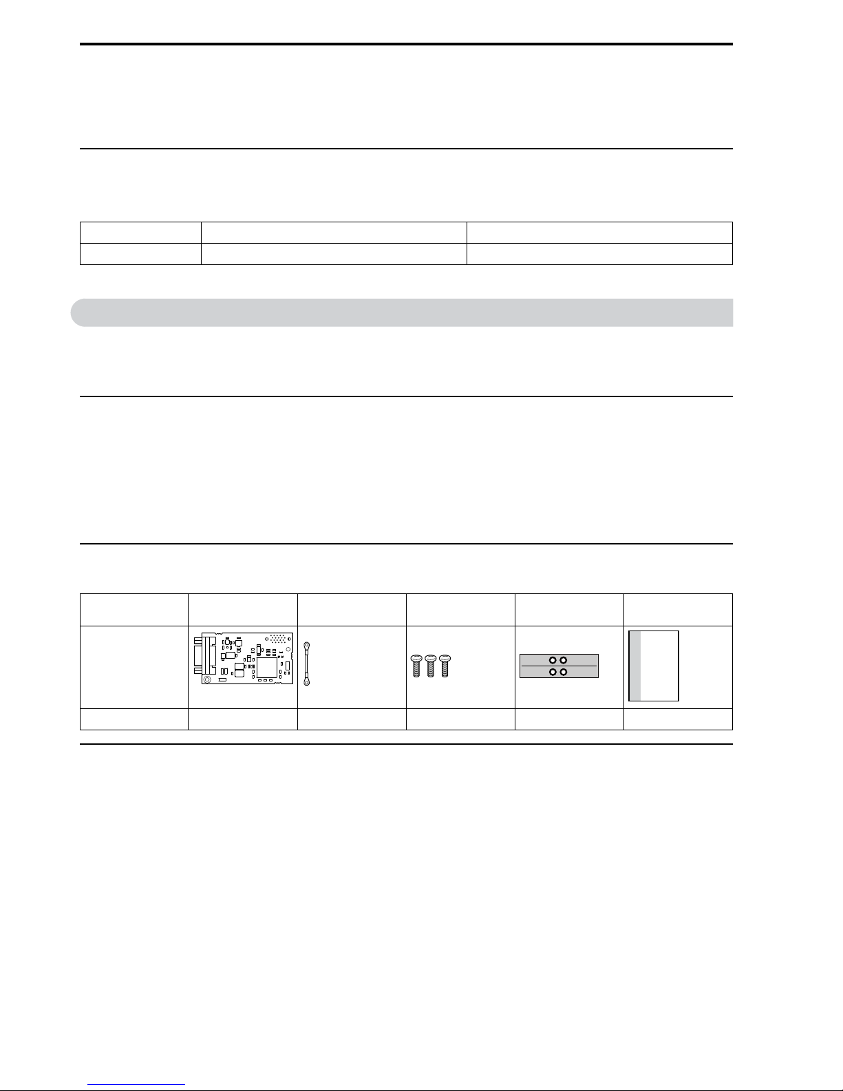
◆Content and Packaging
Table 3.1 Option Package Contents for SI-L3 (Inverter Drive for Lift L1000A)
Description Option Card Ground Cables Screws (M3) LED Label Installation
Manual
Illustration
Quantity 1 1 3 1 1
◆Tools Required
A Phillips screwdriver PH1(#1) or PH2(#2) is required to install the Communication Option card.
Note:
Tools required to prepare communication network cables for wiring are not listed in this manual.
ERR RUN
MANUAL

4 CANopen Lift Option Components
YASKAWA ELECTRIC SIEP YEUOCL1 01A CANopen-Lift Communication Option Installation Manual 9
4 CANopen Lift Option Components
◆CANopen Lift Option SI-L3
A - Communication cable connector
(9 pin D-sub)
B - Connector (CN5)
C - Installation hole
D - LED (RUN)
E - LED (ERR)
F - Model number
G - Ground terminal (installation
hole)
Figure 4.1 Option Card
◆CANopen-Lift Option Status LEDs
The CANopen-Lift Option has two LEDs that indicate the communication status.
■RUN LED
LED Color Display Meaning
RUN Green On The device is in Operational State.
Green Blinking The device is in Pre-Operational State.
Green Single flash The device is stopped.
Green Flickering Automatic bit rate detection in process.
■ERR LED
LED Color Display Meaning
ERR – Off Online.
Red Blinking Bus initialization failed.
Single flash A fault has occurred. Receiving CAN error frames.
Double flash Guard / Heartbeat has occurred.
Flickering Automatic bitrate detection in process.
Flickers with RUN LED alternatively.
On Bus off.
4 CANopen Lift Option Components
10 YASKAWA ELECTRIC SIEP YEUOCL1 01A CANopen-Lift Communication Option Installation Manual
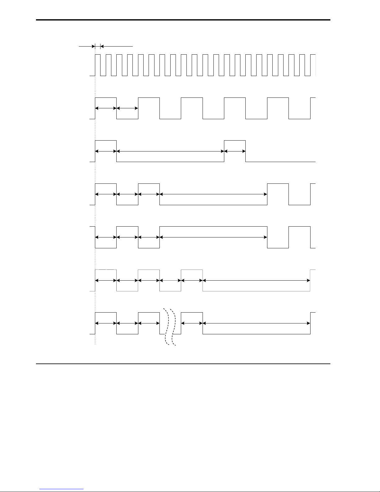
■Indicator Flash Rates
Figure 4.2 Meaning of LED Flash Rates
◆Communication Connector
The Communication Option card is connected to the network using a 9 pin D-sub connector.
flickering
on
50 ms
200 ms
200 ms
200 ms 200 ms 200 ms
200 ms 200 ms 200 ms
200 ms 200 ms 200 ms
200 ms 200 ms 200 ms
200 ms 200 ms
200 ms
1 2 n
200 ms1000 ms
1000 ms
1000 ms
1000 ms
1000 ms
200 ms
off
on
off
on
off
on
off
on
off
on
off
on
off
blinking
single
flash
double
flash
triple
flash
n flashes
inverted
double
flash

4 CANopen Lift Option Components
YASKAWA ELECTRIC SIEP YEUOCL1 01A CANopen-Lift Communication Option Installation Manual 11
Table 4.1 Pin Assignment
Connector Pin Signal Description
1 – –
2 CAN_L CAN_L bus line (dominant low)
3 CAN_GND CAN ground
4 – –
5 CAN_SHLD CAN shield
6 – –
7 CAN_H CAN_H bus line (dominant high)
8 – –
9 – –
– CAN_SHLD CAN shield
■Communication Cable
Connect the CANopen-Lift option card to the network using a 9 pin D-sub connector wired like shown below.
Figure 4.3 Wiring Diagram
Note:
The FE terminal on the Communication Option must be connected to the drive ground terminal using the delivered ground wire.
■Network Termination
Both ends of the CANopen network have to be terminated with a 120 Ohm resistor. If the CANopen option is the
last node in the network, make sure to apply a termination resistor as shown below, because the CANopen option
does not have a built-in termination resistor:
Figure 4.4 Termination Resistor
6
7
8
9
1
2
3
4
5
120 Ω

5 Mechanical & Electrical Installation
12 YASKAWA ELECTRIC SIEP YEUOCL1 01A CANopen-Lift Communication Option Installation Manual
Note:
The FE terminal on the Communication Option must be connected to the drive ground terminal using the delivered ground wire.
5 Mechanical & Electrical Installation
◆Safety Precautions
DANGER Electrical Shock Hazard. Do not examine, connect, or disconnect wiring on an energized drive. Before
servicing, disconnect all power to the equipment and wait for the time specified on the warning label at a minimum. The internal
capacitor stays charged after the drive is de-energized. The charge indicator LED extinguishes when the DC bus voltage
decreases below 50 Vdc. When all indicators are OFF, remove the covers before measuring for dangerous voltages to make
sure that the drive is safe. Failure to obey will cause death or serious injury.
WARNING Electrical Shock Hazard. Do not operate equipment when covers are missing. Some figures in this section
include drives without covers or safety shields to more clearly show the inside of the drive. Replace covers and shields before
operation. Use drives only as specified by the instructions. Failure to obey can cause death or serious injury.
WARNING Electrical Shock Hazard. Do not work on the drive or around the drive while wearing loose clothing or jewelry.
Tighten loose clothing and remove all metal objects such as watches or rings. Failure to obey can cause death or serious injury.
WARNING Electrical Shock Hazard. Do not remove covers or touch circuit boards while the drive is energized. Failure to
obey can cause death or serious injury.
WARNING Electrical Shock Hazard. Only let authorized persons install, wire, maintain, examine, replace parts, and
repair the drive. Failure to obey can cause death or serious injury.
WARNING Electrical Shock Hazard. Do not make changes to the drive body or drive circuitry. Failure to obey can cause
death or serious injury and will void warranty. Yaskawa is not responsible for changes to the product made by the user.
WARNING Fire Hazard. Tighten all terminal screws to the correct tightening torque. Connections that are too loose or too
tight can cause incorrect operation and damage to the drive. Incorrect connections can also cause death or serious injury from
fire.
CAUTION Crush Hazard. Do not hold the drive by the front cover or terminal cover. Tighten the screws correctly before
moving the drive. Failure to obey can cause minor to moderate injury.
NOTICE Observe correct electrostatic discharge (ESD) procedures when touching the drive. Failure to obey can cause
ESD damage to the drive circuitry.
NOTICE Do not lift the drive with the cover removed. Failure to obey can cause damage to the drive board and terminal
block.
NOTICE Do not use unshielded wire for control wiring. Use shielded, twisted-pair wires and ground the shield to the
ground terminal of the drive. Failure to obey can cause electrical interference and unsatisfactory system performance.
NOTICE Do not change the drive circuitry. Failure to obey can cause damage to the drive and will void warranty.
Yaskawa is not responsible for modifications of the product made by the user.
NOTICE Make sure that all connections are correct after you install the drive and connecting peripheral devices.
Failure to obey can cause damage to the drive.
◆Before Installing the Option Card
Prior to installing the Communication Option Card, wire the inverter drive and connect to the drive terminals. For
more information on wiring and connecting the inverter drive, refer to the manual packaged with the inverter
drive.
Verify that the inverter drive runs normally without the option installed.
◆Installing the Option on a L1000A
1. Turn off the power. Wait until the CHARGE LED turns off and then remove the cover. Refer to the drive
manual for direction on removing the front cover.
2. Plug the option card (E) to the CN5-A connector (C).
Fieldbus option cards must always be plugged into CN5-A connector.
3. Connect the ground wire (F) to option card and fix with screw (1).
Select shortest possible cable for ground connection.

5 Mechanical & Electrical Installation
YASKAWA ELECTRIC SIEP YEUOCL1 01A CANopen-Lift Communication Option Installation Manual 13
4. Fix option card to the inverter with screw (2) additionally. Connect the ground wire (F) to inverter ground
terminal (D).
Note:
There are only two screw holes on the drive for ground terminals. If three different option cards are connected, two of the
ground wires will need to share the same ground terminal.
A - Connector CN5-C
B - Connector CN5-B
C - Connector CN5-A
D - Drive grounding terminal (FE)
E - Option cards
F - Ground wire
G - Opening for cable lines (use
cutter to create the opening)
H - Operator
I - LED labels
J - Front cover
Figure 5.1 Installing the Option Card
5. Prepare the 9 pin D-sub network cable connectors.
For inverter drives CIMR-Lx4F0002 to 0023: the network cable should be routed to the outside through
the openings at the left side (G) of the front cover. Make sure no sharp edges remain.
For Inverter drives 4F0031 to 0165: enough space to keep all wiring inside the unit is available.
A - Opening for network cables
(CIMR-Lx4F0002 to 0023)
B - Space for wiring (CIMR-Lx4F0031
to 0165)
Figure 5.2 Network Cable Routing
6. Plug in the 9 pin D-sub network cable connector to the option.
7. Reinstall the front cover back onto the drive as it was before.
8. Attach the LED label (I) as shown in Figure 5.1.
9. Switch on the drive power supply.
10. Set inverter parameter as follows:
F
A
E
H
I
B
C
D
G
J
2
1
ERR RUN
A B

6 CANopen-Lift Option Related Drive Parameters
14 YASKAWA ELECTRIC SIEP YEUOCL1 01A CANopen-Lift Communication Option Installation Manual
b1-01 to 6,
b1-02 to 6,
H5-13 to 5.
11. Powercycle the inverter drive.
◆EDS File
For easy network implementation of drives equipped with a Communication Option card, the EDS file (version
ESI_SIS3L_OPT_V_2_01_04 or later) can be obtained from these sources:
•Europe:
http://www.yaskawa.eu.com
•Japan:
http://www.e-mechatronics.com
•USA:
http://www.yaskawa.com
•Other areas: contact a YASKAWA representative
6 CANopen-Lift Option Related Drive Parameters
Some drive parameters have influence on some functions of the communication option card. Check these
parameters before starting network communications.
Table 6.1 Parameter Settings
No. Name Description Default
b1-01 Frequency Reference Selection Selects the frequency reference input source
0: Operator - Digital preset speed d1-01 to d1-17
1: Terminals - Analog input terminals
2: MEMOBUS/Modbus communications
3: Option card
4: Pulse Input (Terminal RP)
6: DCP/CANopen-Lift
1
b1-02 Run Command Selection Selects the run command input source
0: Digital Operator - RUN and STOP keys
1: Digital input terminals Sx
2: MEMOBUS/Modbus communications
3: Option card
6: DCP/CANopen-Lift
1
F6-01 Operation Selection after
Communications Error
Determines drive response when a bUS error is detected during
communications
0: Ramp to Stop
1: Coast to Stop
2: Fast-Stop
3: Alarm Only *1
1
F6-02 External Fault Detection
Conditions (EF0)
Sets the condition for external fault detection (EF0)
0: Always detected
1: Detected only during operation
0
F6-03 Stopping Method for External
Fault from Communication
Option Board
Determines drive response for external fault input (EF0) detection
0: Ramp to Stop
1: Coast to Stop
2: Fast-Stop
3: Alarm Only
1

7 Troubleshooting
YASKAWA ELECTRIC SIEP YEUOCL1 01A CANopen-Lift Communication Option Installation Manual 15
No. Name Description Default
F6-08 Reset Communication Related
Parameters
Determines if communication-related parameters are set back to
their original default values when the drive is initialized.
0: Do not reset F6-xx and F7-xx parameters when the drive is
initialized using parameter A1-03.
1: Reset F6-xx and F7-xx parameters when the drive is initialized
using parameter A1-03.
Note:
Setting this parameter does not affect communication-related
parameters. Setting this parameter only determines if
communication-related parameters (F6-xx and F7-xx) are also
reset when A1-03 is used to initialize the drive.
0
F6-35 Node Address 0 to 126 2
F6-36 Communication Speed 0: Automatic Bit Rate Detection
1: 10 kbps
2: 20 kbps
3: 50 kbps
4: 125 kbps
5: 250 kbps
6: 500 kbps
7: 800 kbps
8: 1 Mbps
5
H5-13 Serial Comm Mode 0: DCP Communication Channel
1: Memobus/Modbus
3: DCP 3
4: DCP 4
5: CANopen-Lift
1
o1-03 Digital Operator Display
Selection
Sets the units to display the frequency reference and output
frequency.
0: 0.01 Hz
1: 0.01% (100% = E1-04)
2: r/min (enter the number of motor poles to E2-04). Relevant for
CiA-417.
3: User defined by parameters o1-10 and o1-11
*2
o1-20 Traction Sheave Diameter 100.0 to 2000.0 mm 400.0 mm
o1-21 Roping Ratio 1 to 4 2
o1-22 Mechanical Gear Ratio 0.10 to 100.0 In CLV mode:
14.00
In CLV PM
mode: 1.00
*1 If set to 3, then the drive will continue to operate when an EF0 fault is detected. Take proper safety measures, such as installing an
emergency stop switch.
*2 The default value depends on the drive used and/or the drive software version. For details refer to the technical manual for the drive.
7 Troubleshooting
◆Drive-Side Error Codes
Drive-side error codes appear on the drive’s digital operator.
◆Faults
This section gives information about the causes and possible solutions of faults. You must use the Fault Reset
operation to remove the fault before you can operate the drive. Use the information in this table to remove the
cause of the fault.

7 Troubleshooting
16 YASKAWA ELECTRIC SIEP YEUOCL1 01A CANopen-Lift Communication Option Installation Manual
Code Name Causes Possible Solutions
bUS Option Communication
Error
The drive did not receive a signal from
the controller.
The communications cable wiring is
incorrect.
Correct wiring errors.
There is a short circuit or the
communications cable is not connected.
•Repair short circuits and connect cables.
•Replace the defective communications cable.
Electrical interference caused a
communication data error.
•Examine the control circuit lines, main circuit
lines, and ground wiring, and decrease the
effects of electrical interference.
•Make sure that a magnetic contactor is not the
source of the electrical interference, then use a
Surge Protective Device if necessary.
•Use only the recommended cables or other
shielded line. Ground the shield on the controller
side or the drive input power side.
•Isolate the communication wiring from drive
power lines, and install a noise filter to the input
side of the power supply for communication.
•Decrease the effects of electrical interference
from the controller.
The option card is incorrectly installed
to the drive.
Correctly install the option card to the drive.
The option card is damaged. If the fault continues and the wiring is correct,
replace the option card.
CLoE CANopen Lift Operation
Error
Sequence error.
Invalid position data.
•Check shaft encoder.
•Check inverter and lift controller setup and
wiring.
oFA00 Option Not Compatible
with Port
The option card connected to connector
CN5-A is not compatible.
Connect the option card to the correct connector.
Note:
Encoder option cards are not compatible with
connector CN5-A.
oFA01 Option Fault/Connection
Error
The option card connected to connector
CN5-A is not compatible.
1. De-energize the drive.
2. Refer to the option card manual and correctly
connect the option card to the connector on the
drive.
oFA30 to
oFA43
Communication Option
Card Connection Error
(CN5-A)
A fault occurred in the option card. 1. De-energize the drive.
2. Make sure that the option card is correctly
connected to the connector.
3. If the problem continues, replace the option
card.
oFb00 Option Not Compatible
with Port
The option card connected to connector
CN5-B is not compatible.
Connect the option card to the correct connector.
Note:
DO-A3, AO-A3, PG-B3, and PG-X3 options
can connect to connector CN5-B. Use connector
CN5-C when connecting only one encoder
option card.
oFb02 Duplicate Options The same option cards or the same type
of option cards are connected to
connectors CN5-A, B, and C.
Connect the option card to the correct connector.
oFC00 Option Not Compatible
with Port
The option card connected to connector
CN5-C is not compatible.
Connect the option card to the correct connector.
Note:
AI-A3, DI-A3, and communication option cards
cannot be connected to the CN5-C connector.
oFC02 Duplicate Options The same option cards or the same type
of option cards are connected to
connectors CN5-A, B, and C.
Connect the option card to the correct connector.
PE1 Programming Error 1 Object content mapping was changed
from the default. A Node reset was sent
while the drive was running.
Stop the drive before performing Node reset.

8 Specifications
YASKAWA ELECTRIC SIEP YEUOCL1 01A CANopen-Lift Communication Option Installation Manual 17
◆Minor Faults/Alarms
This section gives information about the causes and possible solutions when a minor fault or alarm occurs. Use
the information in this table to remove the cause of the minor fault or alarm.
Code Name Causes Possible Solutions
AEr Station Address Setting
Error
Option card node address is outside of
the acceptable setting range.
For CANopen communication, set F6-35
[CANopen Node ID Selection] correctly.
CALL Serial Comm Transmission
Error
The communications cable wiring is
incorrect.
Correct any wiring errors.
There is a short circuit or the
communications cable is not connected.
•Repair short circuits and connect cables.
•Replace the defective communications cable.
There was a programming error on the
controller side.
Examine communications at start-up and correct
programming errors.
The communications circuitry is
damaged.
•Do a self-diagnostics check.
•If the problem continues, replace the control
board or the drive. For information about
replacing the control board, contact Yaskawa or
your nearest sales representative.
The termination resistor setting for
MEMOBUS/Modbus communications
is incorrect.
On the last drive in a MEMOBUS/Modbus
network, set DIP switch S2 to the ON position to
enable the termination resistor.
EEP EEPROM Checksum Error Communication wiring is faulty, there is
a short circuit, or something is not
connected properly.
Correct any wiring errors.
EEPROM checksum error. •If these errors occur, the object dictionary will be
reset to its default values. After the object
dictionary has been changed and object
dictionary contents are then changed, execute a
Store Parameter command (Index = 1010 (Hex)).
•If the object dictionary has not been changed,
execute a Restore Parameter command (Index =
1011 (Hex)).
Programming error occurred on the
controller side.
Check communications at start-up and correct
programming errors.
Communications circuitry is damaged. •Perform a self-diagnostics check.
•If the problem continues, replace either the
control board or the entire drive. For instructions
on replacing the control board, contact Yaskawa
or your nearest sales representative.
8 Specifications
Item Specification
Model SI-L3
Communication Profile CiA-301 Ver. 4.02
CiA-417 Ver. 2.2.0, Profile Velocity and Profile Position
Connector 9 pin D-sub connector
Communication Speed 10 kbps to 1 Mbps
Ambient Temperature -10 °C to +50 °C
Humidity up to 95% RH (non-condensing)
Storage Temperature -20 °C to +60 °C
Area of Use Indoor (free of corrosive gas, airborne particles, etc.)
Altitude Up to 1000 m

18 YASKAWA ELECTRIC SIEP YEUOCL1 01A CANopen-Lift Communication Option Installation Manual
Revision History
Date of
Publication
Revision
Number Section Revised Content
November 2017 ––First Edition

YASKAWA ELECTRIC SIEP YEUOCL1 01A CANopen-Lift Communication Option Installation Manual 19

CANopen-Lift Communication
Option
Communication Option Card for Lift Inverter Drive
YASKAWA L1000A
In the event that the end user of this product is to be the military and said product is to be
employed in any weapons systems or the manufacture thereof, the export will fall under the
relevant regulations as stipulated in the Foreign Exchange and Foreign Trade Regulations.
Therefore, be sure to follow all procedures and submit all relevant documentation according
to any and all rules, regulations and laws that may apply.
Specifications are subject to change without notice for ongoing product modifications and
improvements.
© 2017 YASKAWA Europe GmbH
YASKAWA Europe GmbH
MANUAL NO. SIEP YEUOCL1 01A <1>-0
Published in Germany January 2017
17-1
Original instructions
*SIEPYEUOCL101*
YASKAWA EUROPE GmbH
Hauptstraβe 185, 65760 Eschborn, Germany
Phone: +49-6196-569-500
E-mail: [email protected]
http://www.yaskawa.eu.com
DRIVE CENTER (INVERTER PLANT)
2-13-1, Nishimiyaichi, Yukuhashi, Fukuoka, 824-8511, Japan
Phone: +81-930-25-2548 Fax: +81-930-25-3431
http://www.yaskawa.co.jp
YASKAWA AMERICA, INC.
2121, Norman Drive South, Waukegan, IL 60085, U.S.A.
Phone: +1-800-YASKAWA (927-5292) or +1-847-887-7000 Fax: +1-847-887-7310
http://www.yaskawa.com
Other manuals for L1000A Series
5
Table of contents
Other YASKAWA Inverter Drive manuals


