YASKAWA JVOP-182 User manual
MANUAL NO. TOBP C730600 35B
形式 JVOP-182
取扱説明書
LEDオペレータ
安川インバータオプション
製品を安全にお使い頂くために,この取扱説明書を必ずお読みください。
また,本書をお手元に保管していただくとともに,最終的に本製品をご使用になる
ユーザー様のお手元に確実に届けられるよう,お取り計らい願います。
To properly use the product, read this manual thoroughly and retain
for easy reference, inspection, and maintenance. Ensure the end user
receives this manual.
Installation Manual
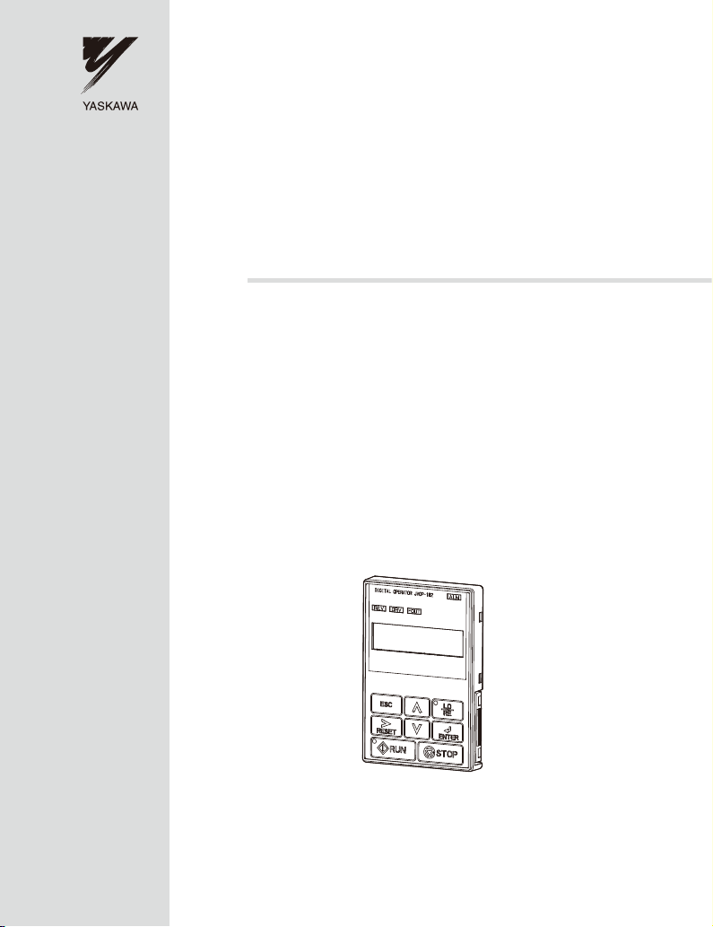
LED Operator
YASKAWA AC Drive Option
Type JVOP-182

YAS KAWA ELECT RI C TOBP C730600 35B YASKAWA AC Drive Option LED Operator Installation Manual 3
Table of Contents
1 PREFACE AND SAFETY . . . . . . . . . . . . . . . . . . . . . . . . . . . . 4
2 PRODUCT OVERVIEW . . . . . . . . . . . . . . . . . . . . . . . . . . . . . . 8
3 RECEIVING . . . . . . . . . . . . . . . . . . . . . . . . . . . . . . . . . . . . . . . 9
4 LED OPERATOR OPTION COMPONENTS . . . . . . . . . . . . . 11
5 INSTALLATION PROCEDURE . . . . . . . . . . . . . . . . . . . . . . .16
6 BASIC OPERATION . . . . . . . . . . . . . . . . . . . . . . . . . . . . . . . 22
7 RELATED PARAMETERS . . . . . . . . . . . . . . . . . . . . . . . . . . 24
8 LED OPERATOR OPTION FAULT DIAGNOSTICS . . . . . . . 26
9 SPECIFICATIONS . . . . . . . . . . . . . . . . . . . . . . . . . . . . . . . . .28
10 REVISION HISTORY . . . . . . . . . . . . . . . . . . . . . . . . . . . . . . 29
Copyright © 2008 YASKAWA ELECTRIC CORPORATION
All rights reserved. No part of this publication may be reproduced, stored in a
retrieval system, or transmitted, in any form or by any means, mechanical,
electronic, photocopying, recording, or otherwise, without the prior written
permission of Yaskawa. No patent liability is assumed with respect to the use of the
information contained herein. Moreover, because Yaskawa is constantly striving to
improve its high-quality products, the information contained in this manual is
subject to change without notice. Every precaution has been taken in the
preparation of this manual. Yaskawa assumes no responsibility for errors or
omissions. Neither is any liability assumed for damages resulting from the use of
the information contained in this publication.

4 YASKAWA ELECTRIC TOBP C730600 35B YASKAWA AC Drive Option LED Operator Installation Manual
1 Preface and Safety
1 Preface and Safety
Yaskawa manufactures products used as components in a wide variety of industrial systems
and equipment. The selection and application of Yaskawa products remain the responsibility
of the equipment manufacturer or end user. Yaskawa accepts no responsibility for the way its
products are incorporated into the final system design. Under no circumstances should any
Yaskawa product be incorporated into any product or design as the exclusive or sole safety
control. Without exception, all controls should be designed to detect faults dynamically and
fail safely under all circumstances. All systems or equipment designed to incorporate a
product manufactured by Yaskawa must be supplied to the end user with appropriate
warnings and instructions as to the safe use and operation of that part. Any warnings
provided by Yaskawa must be promptly provided to the end user. Yaskawa offers an express
warranty only as to the quality of its products in conforming to standards and specifications
published in the Yaskawa manual. NO OTHER WARRANTY, EXPRESSED OR IMPLIED,
IS OFFERED. Yaskawa assumes no liability for any personal injury, property damage,
losses, or claims arising from misapplication of its products.
1 Preface and Safety
YASKAWA ELECTRIC TOBP C730600 35B YASKAWA AC Drive Option LED Operator Installation Manual 5
◆Applicable Documentation
The following manuals are available for the JVOP-182 LED Operator Option:
For the drive setup, refer to the drive Quick Start Guide or Technical Manual.
LED Operator
Yaskawa AC Drive Option LED Operator Installation Manual
Read this manual first.
The installation manual is packaged with the LED Operator Option and
contains a basic overview of wiring, settings, functions, and fault
diagnoses.
RS-232C Interface Option
Yaskawa AC Drive -RS-232C Interface Option Technical Manual
The Technical Manual is packaged with the RS-232C Interface Option and
contains a basic overview of wiring, settings, functions, and fault diagnoses.
Yaskawa Drive
Refer to the manual of the drive this option is being used with.
The manual for the drive covers basic installation, wiring, operation procedures, functions,
troubleshooting, and maintenance information.
It also includes important information on parameter settings and how to tune the drive.
To obtain instruction manuals for Yaskawa products access these sites:
Europe: http://www.yaskawa.eu.com
Japan: http://www.e-mechatronics.com
Other areas: contact a Yaskawa representative.
J1000
J1000
STOP
Read manual before installing.
Wait 1 minute for capacitor discharge after
disconnecting power supply.
To conform to requirements, make sure
to ground the supply neutral for 400V class.
Risk of electric shock.
WARNING
1
2
3
4
5
:
:
:
:
:
:
:
:
:
6
7
8
9
据え付け、運転の前には必ず取扱説明書を読むこと。
通電中および電源遮断後
外さないこと。
級インバータの場合は、電源の中性点が接地
されていることを確認すること。( 対応)
周波数指令
正転逆転選択
出力周波数
出力電流
出力電圧
モニタ
ベリファイ
セットアップ
パラメータ設定
400V
けが、感電のおそれがあります。
危 険
1
分以内はフロントカバーを

1 Preface and Safety
6YASKAWA ELECTRIC TOBP C730600 35B YASKAWA AC Drive Option LED Operator Installation Manual
◆Terms
◆Registered Trademarks
Company names and product names listed in this manual are the registered trademarks of
those companies.
◆Supplemental Safety Information
Read and understand this manual before installing, operating or servicing this option unit.
The option unit must be installed according to this manual and local codes.
The following conventions are used to indicate safety messages in this manual. Failure to
heed these messages could result in serious or possibly even fatal injury or damage to the
products or to related equipment and systems.
Note: Indicates a supplement or precaution that does not cause drive damage.
≥1010: Indicates a drive feature or function that is only available in drive software
version 1010 or greater.
LED: Light emitting diode.
DANGER
Indicates a hazardous situation, which, if not avoided, will result in death or serious
injury.
WARNING
Indicates a hazardous situation, which, if not avoided, could result in death or
serious injury.
CAUTION
Indicates a hazardous situation, which, if not avoided, could result in minor or
moderate injury.

1 Preface and Safety
YASKAWA ELECTRIC TOBP C730600 35B YASKAWA AC Drive Option LED Operator Installation Manual 7
■General Safety
NOTICE
Indicates an equipment damage message.
General Precautions
• The diagrams in this section may include option units and drives without covers or safety shields to
illustrate details. Be sure to reinstall covers or shields before operating any devices. The option board
should be used according to the instructions described in this manual.
• Any illustrations, photographs, or examples used in this manual are provided as examples only and
may not apply to all products to which this manual is applicable.
• The products and specifications described in this manual or the content and presentation of the
manual may be changed without notice to improve the product and/or the manual.
• When ordering a new copy of the manual due to damage or loss, contact your Yaskawa
representative or the nearest Yaskawa sales office and provide the manual number shown on the
front cover.
DANGER
Heed the safety messages in this manual.
Failure to comply will result in death or serious injury.
The operating company is responsible for any injuries or equipment damage resulting
from failure to heed the warnings in this manual.
NOTICE
Do not expose the drive to halogen group disinfectants.
Failure to comply may cause damage to the electrical components in the option unit.
Do not pack the drive in wooden materials that have been fumigated or sterilized.
Do not sterilize the entire package after the product is packed.
8 YASKAWA ELECTRIC TOBP C730600 35B YASKAWA AC Drive Option LED Operator Installation Manual
2 Product Overview
2 Product Overview
◆About This Product
The LED Operator Option provides an enhanced drive user interface that can operate the
Yaskawa drive at a short distance up to 3 meters. The LED Operator Option is an LED
display that simplifies the task of interfacing with the drive to perform these tasks:
• Read or modify drive parameters.
• Read and copy drive parameter settings to another Yaskawa drive.
• Operate the drive.
• Monitor drive operation status.
◆Applicable Models
The LED Operator Option can be used with the drive models in Table 1.
Table 1 Applicable Drive Models
All keys except for the STOP key on the drives built-in LED operator will not function when
the LED Operator Option is connected to V1000 and J1000. <1>
<1> If desired, to also disable the STOP key on the drives built-in LED operator, set parameter o2-02 (STOP Key
Function Selection) to 0 (Disabled).
Drive Drive Software Version <1>
<1> See “PRG” on the drive nameplate for software version number.
A1000 ≥1010
J1000 ≥1010
V1000 ≥1016

YASKAWA ELECTRIC TOBP C730600 35B YASKAWA AC Drive Option LED Operator Installation Manual 9
3 Receiving
3 Receiving
Perform the following tasks after receiving the LED Operator Option:
• Inspect the LED Operator Option for damage.
If the LED Operator Option appears damaged upon receipt, contact the shipper
immediately.
• Verify receipt of the correct model by checking the model number printed on the Name
plate of the LED Operator Option.
• If you have received the wrong model or the LED Operator Option does not function
properly, contact your supplier.
◆Contents and Packaging
Table 2 Contents of Package
■Additional Part Required (Sold Separately)
Proper installation of the LED Operator Option requires a communication cable. A
communication cable is not provided. A connection cable can be purchased from Yaskawa
or recommended LAN cables may be used. Refer to Table 3 for more information regarding
the cable required for your application.
Depending on the LED Operator Option installation method, an installation support listed in
Tabl e 3 may also be required. Refer to Installing the LED Operator Option on page 17 for
more information regarding installation methods.
To order a cable or an installation support, contact Yaskawa directly or your nearest Yaskawa
distributor.
Description: LED Operator Option Installation Manual
–
Quantity: 11
MANUAL

3 Receiving
10 YASKAWA ELECTRIC TOBP C730600 35B YASKAWA AC Drive Option LED Operator Installation Manual
Table 3 Item Names and Part Numbers (Sold Separately)
◆Tool Requirements
To install the LED operator on the door of the enclosure panel, the following tools are
required:
Table 4 Required Tools
Item
<1> If weld studs are on the back of the panel, use the Installation Support Set B.
<2> Alternate cables (customer supplied), RJ45 8 pin Straight Connector UTP Cat 5e cable.
<3> To connect the LED operator to J1000, install the RS-232C Interface Option to the drive.
Yaskawa Part Number Notes Page
RS-232C Interface Option
SI-232/J <3> 20
Communication Cable (1 m)
WV001 <2> Sold Separately 20
Communication Cable (3 m)
WV003 <2> Sold Separately 20
Installation Support Set A
EZZ020642A
Sold Separately;
For use with holes
through the panel
18
Installation Support Set B <1>
EZZ020642B
Sold Separately;
For use with panel
mounted threaded studs
19
Installation Location Installation Support Required Tools
External/Face Mount – Phillips screwdriver, M3
Internal/Flush Mount
Installation Set A Phillips screwdriver, M3, M4
Installation Set B Phillips screwdriver, M3
Box end or adjustable wrench, M4
J1000
YASKAWA ELECTRIC TOBP C730600 35B YASKAWA AC Drive Option LED Operator Installation Manual 11
4 LED Operator Option Components
4 LED Operator Option Components
◆LED Operator Option
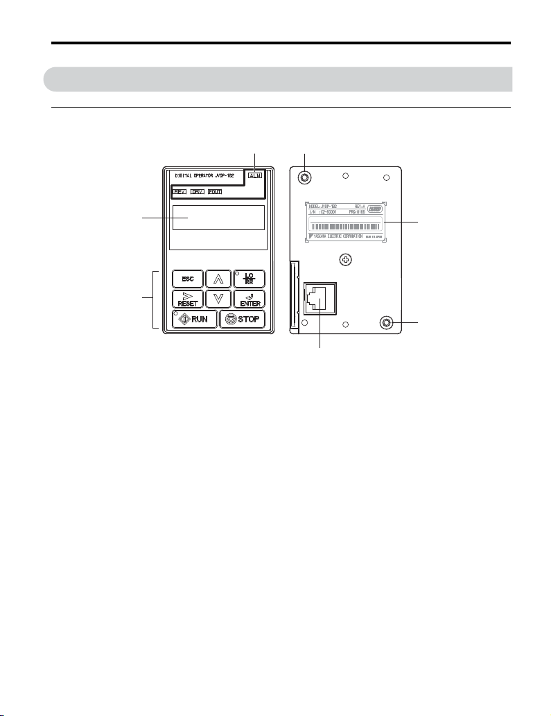
Figure 1
Figure 1 LED Operator Option Components
A – Data Display Area D – Installation Mounting Holes
B – LED Indicators E – Nameplate
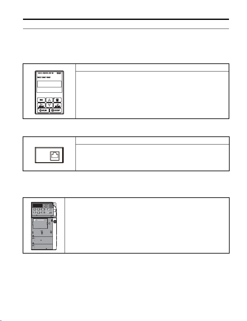
C – Keys F – Communication Cable Connector
S / N : J007XE273710001
B
A
C
D
F
D
E

4 LED Operator Option Components
12 YASKAWA ELECTRIC TOBP C730600 35B YASKAWA AC Drive Option LED Operator Installation Manual
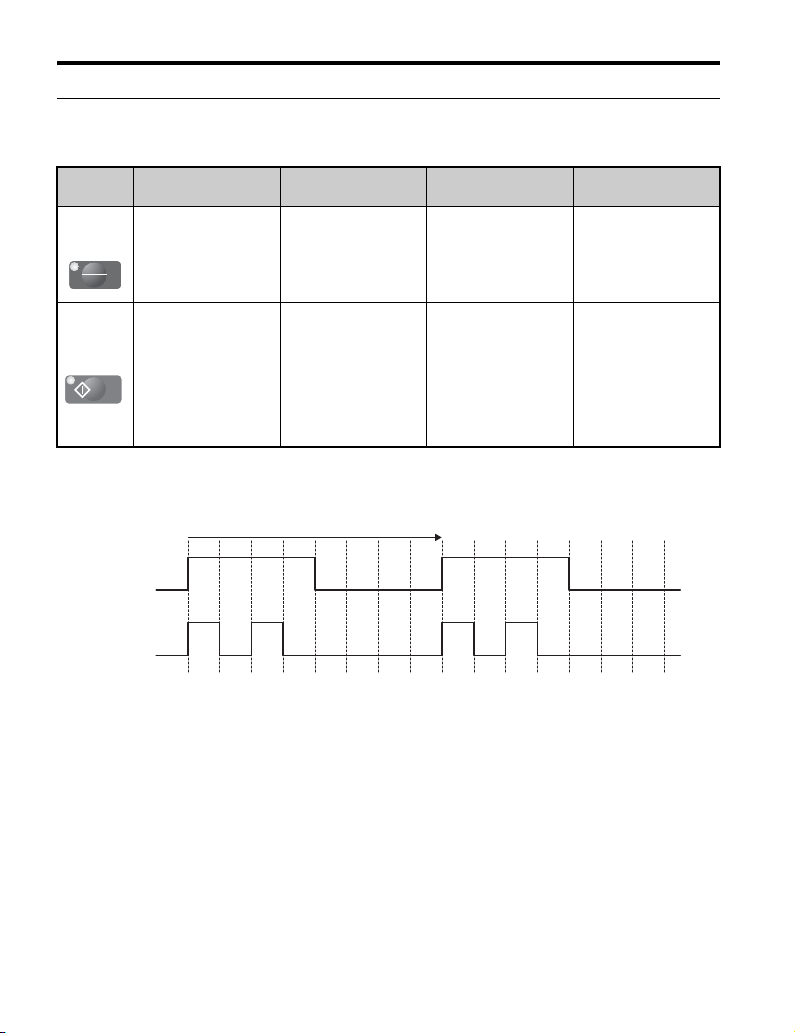
◆Keys
Refer to Figure 2 and Table 5 for details on key names and functions.
Figure 2
Figure 2 Keys
Table 5 Key Names and Functions
No. Key Name Function
1ESCKey
• Returns to the previous display.
• Moves the cursor one space to the left.
• Pressing and holding this button will return to the Frequency
Reference display.
2RESETKey
• Moves the cursor to the right.
• Resets the drive to clear a fault situation.
3 RUN Key Starts the drive and motor.
4Up Arrow
Key
Scrolls up to display the next item, selects parameter numbers
and increments setting values.
ALM
REV DRV FOUT
LO
RE
ESC
RUN STOP
ENTERRESET
DIGITAL OPERATOR JVOP-182
1
2
345 6
9
14 13 12
10
8
11
7
R
R
U
U
N

4 LED Operator Option Components
YASKAWA ELECTRIC TOBP C730600 35B YASKAWA AC Drive Option LED Operator Installation Manual 13
5Down Arrow
Key
Scrolls down to display the next item, selects parameter numbers
and increments setting values.
6STOPKey
Stops drive operation.
Note: The STOP key can be enabled or disabled when operating
from the external terminal or network communications by setting
parameter o2-02.
7ENTERKey
• Enters parameter values and settings.
• Selects a menu item to move between displays.
8
LO/RE
Selection
Key
Switches the drive between operator (LOCAL) control and
control circuit terminals (REMOTE).
Note: The LOCAL/REMOTE key is only effective at a stop in
drive mode. As a safety precaution, it is possible to disable the
LO/RE Selection Key by setting parameter o2-01 (LOCAL/
REMOTE Key Function Selection) to “0” (disabled). <1>
9 RUN Light
Illuminated while the drive is operating the motor.
Refer to LED Operator LED Status Indicators on page 14 for
detail.
10 LO/RE Light Illuminated while the drive is under LED Operator control when
(LOCAL) is selected to run the drive.
11 ALM LED
Light
Refer to LED Screen Display on page 15
12 REV LED
Light
13 DRV LED
Light
14 FOUT LED
Light
<1> o2-01(LOCAL/REMOTE Key Function Selection) is not compatible with J1000. LO/RE Selection Key is always
effective.
No. Key Name Function
S
T
T
O
O
TO
TO
P
RE
LO
4 LED Operator Option Components
14 YASKAWA ELECTRIC TOBP C730600 35B YASKAWA AC Drive Option LED Operator Installation Manual
◆LED Operator LED Status Indicators
Table 6 LED Status and Meaning
Figure 3
Figure 3 RUN LED Status
LED Illuminated Flashing <1>
<1> For the difference between “Flashing” and “Flashing Quickly” of the RUN LED, refer to Figure 3, RUN LED
Status.
Flashing
Quickly <1> Off
LO/RE
LED
When the run
command is selected
from the LED
operator (LOCAL).
––
Run command is
selected from a
device other than the
LED operator
(REMOTE).
RUN LED
During run.
• During
deceleration to
stop.
• When a run
command is input
and the frequency
reference is 0 Hz.
•During
deceleration at a
fast-stop.
• During stop by
External Fault
digital input.
During stop.
RE
LO
RUN
Flashing
quickly
Flashing
ONON
ON
ONON
ON
1 s
4 LED Operator Option Components
YASKAWA ELECTRIC TOBP C730600 35B YASKAWA AC Drive Option LED Operator Installation Manual 15
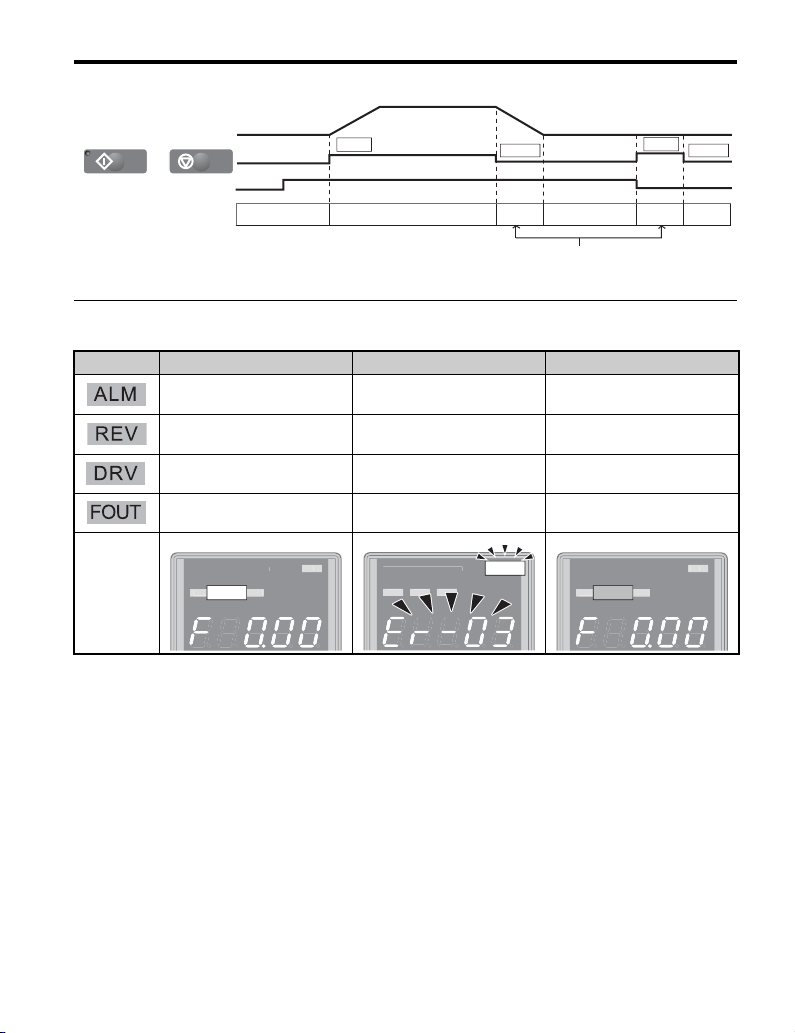
Figure 4
Figure 4 RUN LED and Drive Operation
◆LED Screen Display
Display Lit Flashing Off
When the drive detects an alarm
or error
• When an alarm occurs
• OPE detected Normal state (no fault or alarm)
Motor is rotating in reverse – Motor is rotating forward
Drive Mode – Programming Mode
Displays output frequency (Hz) – –
As illustrated
in this manual
Drive output frequency
During stop
Frequency setting
OFF ON
Flashing
OFFOFF
RUN LED
STOP STOP
RUN
0 Hz 6 Hz
RUN
/
RUN STOP
AL
M
REV
DRV
FO
UT
D
IGITAL OPERATOR JVOP-182
DRV
AL
M
REV
DRV
FOU
T
D
I
G
ITAL
O
PERAT
O
R
J
V
O
P-1
8
2ALM
AL
M
REV
DRV
FO
UT
D
IGITAL OPERATOR JVOP-182
DRV

16 YASKAWA ELECTRIC TOBP C730600 35B YASKAWA AC Drive Option LED Operator Installation Manual
5 Installation Procedure
5 Installation Procedure
◆Section Safety
NOTICE
Damage to Equipment
Use only Yaskawa connection cables or recommended cables.
Failure to comply may cause the drive or LED Operator Option to function incorrectly.
Properly connect the connectors.
Failure to comply may prevent proper operation and possibly damage equipment.
Do not exceed communication cable bend radius specifications.
Failure to comply may result in broken wires or loose connections.

5 Installation Procedure
YASKAWA ELECTRIC TOBP C730600 35B YASKAWA AC Drive Option LED Operator Installation Manual 17
◆LED Operator Option Dimensions
Figure 5
Figure 5 Dimensions
◆Installing the LED Operator Option
There are two different installation methods for the LED Operator Option depending on the
application.
1. External/Face-mount: Mounted outside a panel.
2. Internal/Flush-mount: Mounted inside a panel.
Table 7 LED Operator Option Installation Methods
<1> Use only Yaskawa cables or cables recommended by Yaskawa. Refer to Item Names and Part Numbers (Sold
Separately) on page 10
Installation Method Description Notes
External/Face-mount
Simplified installation with the LED Operator is
mounted on the outside of the panel with two
screws.
–
S / N : J007XE273710001
90 (3.54)
78 (3.07)
60 (2.36) 7.9
(0.31)
minimum
50 (1.97) Unit: mm (in)
12.2
(0.48)
1.6 (0.06) Installation holes (2-M3 screws, dept h 5 (0. 2))
44 (1.73)
15 (0.59)
<1>

5 Installation Procedure
18 YASKAWA ELECTRIC TOBP C730600 35B YASKAWA AC Drive Option LED Operator Installation Manual
NOTICE: Prevent foreign matter such as metal shavings or wire clippings from falling into the drive during
installation and project construction. Failure to comply could result in damage to the drive. Place a
temporary cover over the top of the drive during installation. Remove the temporary cover before startup, as
the cover will reduce ventilation and cause the drive to overheat.
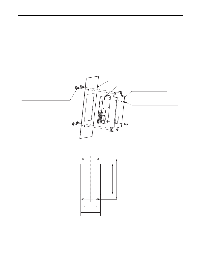
■External/Face-mount Installation
1. Cut an opening in the enclosure panel for the LED Operator Option according to
Figure 6.
2. Position the LED Operator Option so the LED display faces outwards, and mount
it to the enclosure panel as shown in Figure 6.
Figure 6
Figure 6 External/Face-mount Installation
Figure 7
Figure 7 Panel Cut-out Dimensions (External/Face-mount Installation)
Internal/Flush-mount
Encloses the LED Operator Option in the panel.
The LED Operator is flush with the outside of the
panel.
Requires purchase of
separate items. Refer to
Item Names and Part
Numbers (Sold
Separately) on page 10
Installation Method Description Notes
LED Operator Option M3 × 6 (0.24)
Phillips recessed
pan head machine screw × 2
Enclosure panel
Unit: mm (in)
22 (0.87)
22(0.87)
14
(0.55) Unit : mm (in)
26
(1.02)
22
(0.87)
78 (3.07)
2 (0.08)
5 Installation Procedure
YASKAWA ELECTRIC TOBP C730600 35B YASKAWA AC Drive Option LED Operator Installation Manual 19
■Internal/Flush-mount Installation
The internal flush-mount installation method requires an installation support that is
purchased separately. Refer to Item Names and Part Numbers (Sold Separately) on
page 10 for information regarding the installation support and mounting hardware. Figure 8
illustrates how to attach the Installation Support A.
1. Cut an opening in the enclosure panel for the LED Operator Option according to
Figure 9.
2. Mount the LED Operator Option to the installation support (sold separately).
3. Mount the installation support and LED Operator Option to the enclosure panel.
Figure 8
Figure 8 Internal/Flush Mount Installation
Note: For environments with a significant amount of dust or other airborne debris, use a gasket
between the enclosure panel and the LED Operator Option.
Figure 9
Figure 9 Panel Cut-out Dimensions (Internal/Flush-mount Installation)
Enclosure panel
Unit: mm (in)
LED Operator
Installation Support A
M4 × 10 (0.39)
Phillips truss head screw × 4
(for panel widths between
1 (0.04) and 1.6 (0.06)) M3 × 6 (0.24)
Phillips recessed
pan head machine screw × 2
120 (4.72)
Unit : mm (in)
45 (1.77)
89 +0.5
0 35 )( +0.02
0
59+0.5
0 2.32 )( +0.02
0

5 Installation Procedure
20 YASKAWA ELECTRIC TOBP C730600 35B YASKAWA AC Drive Option LED Operator Installation Manual
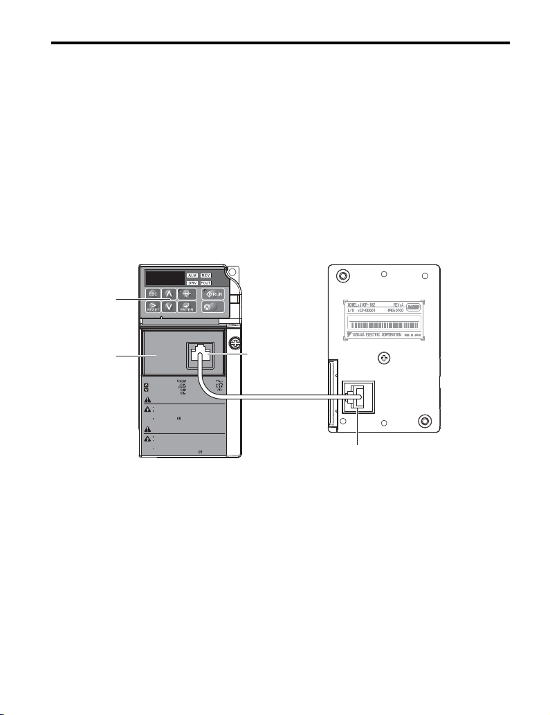
◆Connecting the LED Operator Option to the Drive
This section contains instructions for connecting the LED operator to V1000 and J1000. For
instructions on connecting the LED operator to the other drives, see the Technical Manual of
the drive connected to the LED operator.
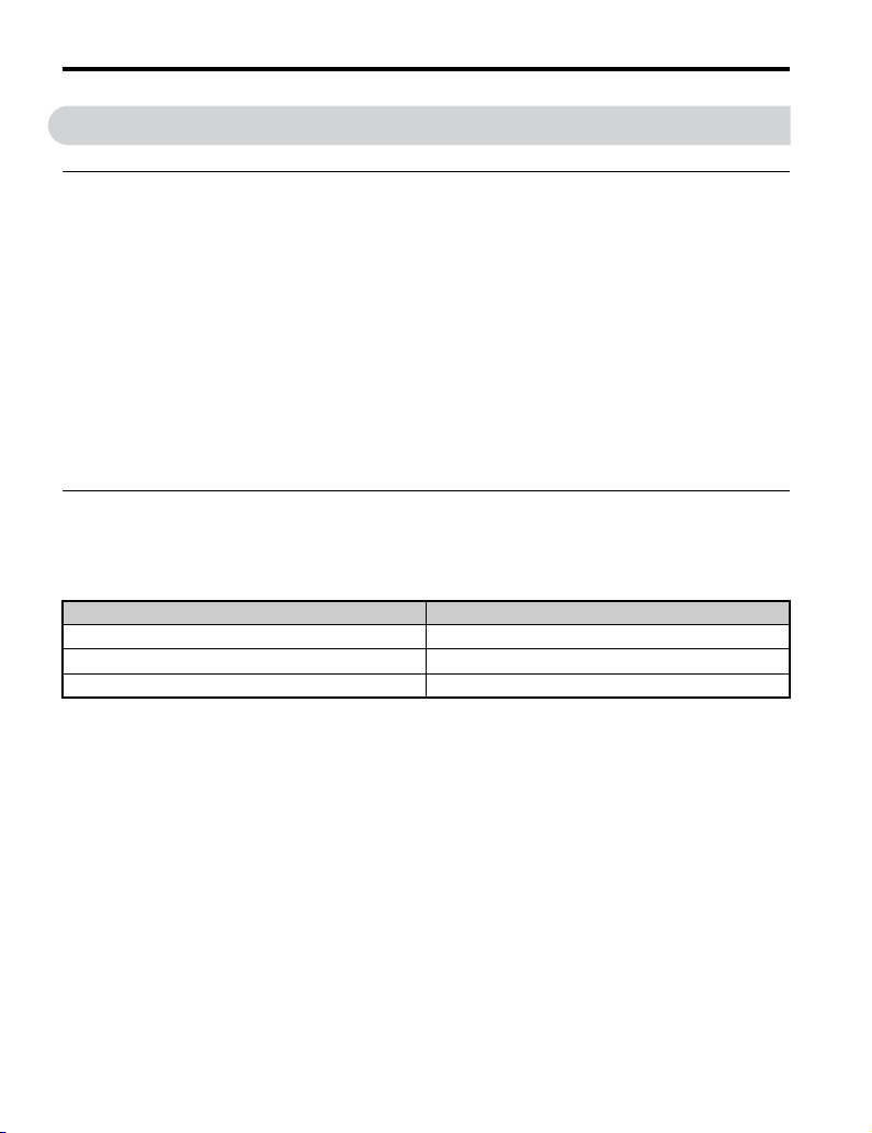
■Connecting the LED Operator Option to V1000
Plug the communication cable into the communication cable connector of the LED Operator
Option and the drive communications port as shown in Figure 11. Ensure both cable ends
are firmly connected. Refer to Item Names and Part Numbers (Sold Separately) on
page 10 for information regarding recommended cables.
Note: Use only Yaskawa recommended cables. Using a cable not specified may cause the LED
Operator or drive to malfunction.
Note: The STOP key on the drives built-in LED operator is the only functional key on the built-in LED
operator when the LED Operator Option is connected to the drive and parameter b1-02 is set to 0
(LED Operator Option). To disable the STOP key, set parameter o2-02 (STOP key Function
Selection) to 0 (Disable).
Figure 10
Figure 10 Communication Cable Connection
S / N : J007XE273710001
STOP
V1000
(Hz)
(Hz)
(A)
(V)
:
:
:
:
:
:
:
:
:
:
周波数指令
正転逆転選択
出力周波数
出力電流
出力電圧
モニタ
ベリファイ
セットアップ
パラメータ設定
オートチューニング
据え付け、運転の前には必ず取扱説明書を読むこと。
通電中および電源遮断後
5
分以内はフロントカバーを
外さないこと。
400V
級インバータの場合は、電源の中性点が接地
されていることを確認すること。( 対応)
けが、感電のおそれがあります。
危 険
Read manual before installing.
Wait 5 minutes for capacitor discharge after
disconnecting power supply.
To conform to requirements, make sure
to ground the supply neutral for 400V class.
Risk of electric shock.
WARNING
LED Operator Option (JVOP-182)
Communication Cable Connector
Comm Port
LED
Operator
Drive
5 Installation Procedure
YASKAWA ELECTRIC TOBP C730600 35B YASKAWA AC Drive Option LED Operator Installation Manual 21
■Connecting the LED Operator to J1000
Note: Attach the RS-232C Interface Option (SI-232/J) to the drive before connecting the LED
Operator Option to the drive.
Plug the communication cable into the communication cable connector of the LED Operator
Option and the communications port of the RS-232C Interface Option (SI-232/J) as shown
in Figure 11. Ensure both cable ends are firmly connected. Refer to Item Names and Part
Numbers (Sold Separately) on page 10 for information regarding recommended cables.
NOTICE: Use only Yaskawa recommended cables. Using a cable not specified may cause the LED
Operator or drive to malfunction.
Note: The STOP key on the drives built-in LED operator is the only functional key on the built-in LED
operator when the LED Operator Option is connected to the drive and parameter b1-02 is set to 0
(LED Operator Option). To disable the STOP key, set parameter o2-02 (STOP key Function
Selection) to 0 (Disable).
Figure 11
Figure 11 Communication Cable Connection
STOP
J1000
S / N : J007XE273710001
Read manual before installing.
Wait 1 minute for capacitor discharge after
disconnecting power supply.
To conform to requirements, make sure
to ground the supply neutral for 400V class.
Risk of electric shock.
WARNING
1
2
3
4
5
:
:
:
:
:
:
:
:
:
6
7
8
9
据え付け、運転の前には必ず取扱説明書を読むこと。
通電中および電源遮断後
1
分以内はフロントカバー を
外さないこと。
400V
級インバータの場合は、電源の中性点が接地
されていることを確認すること。( 対応)
けが、感電のおそれがあります。
危 険
周波数指令
正転逆転選択
出力周波数
出力電流
出力電圧
モニタ
ベリファイ
セットアップ
パラメータ設定
Comm Port
LED Operator Option (JVOP-182)
LED
Operator
RS-232C
Interface
Option
Drive
Communication Cable Connector
This manual suits for next models
1
Table of contents
Other YASKAWA Inverter Drive manuals


