YASKAWA SI-T3 MECHATROLINK-II A1000 Series User manual

MECHATROLINK-II 通信
安川1000シリーズオプション
取扱説明書
形 式 SI-T3
MECHATROLINK-II
YASKAWA 1000-Series Option
Installation Manual
Type: SI-T3
To properly use the product, read this manual thoroughly and retain
for easy reference, inspection, and maintenance. Ensure the end user
receives this manual.
製品を安全にお使い頂くために,本書を必ずお読みください。
また,本書をお手元に保管していただくとともに,最終的に本製品をご使用になる
ユーザー様のお手元に確実に届けられるよう,お取り計らい願います。
MANUAL NO. TOBP C730600 50C

2 YASKAWA ELECTRIC TOBP C730600 50C YASKAWA 1000-Series Option SI-T3 Installation Manual
Copyright © 2008 YASKAWA ELECTRIC CORPORATION
All rights reserved. No part of this publication may be reproduced, stored in a retrieval system, or
transmitted, in any form or by any means, mechanical, electronic, photocopying, recording, or otherwise,
without the prior written permission of Yaskawa. No patent liability is assumed with respect to the use of the
information contained herein. Moreover, because Yaskawa is constantly striving to improve its high-quality
products, the information contained in this manual is subject to change without notice. Every precaution has
been taken in the preparation of this manual. Yaskawa assumes no responsibility for errors or omissions.
Neither is any liability assumed for damages resulting from the use of the information contained in this
publication.

YAS KAWA ELE CT RI C TOBP C730600 50C YASKAWA 1000-Series Option SI-T3 Installation Manual 3
Table of Contents
1 PREFACE AND SAFETY . . . . . . . . . . . . . . . . . . . . . . . . . . . 4
2 PRODUCT OVERVIEW . . . . . . . . . . . . . . . . . . . . . . . . . . . . 8
3 RECEIVING. . . . . . . . . . . . . . . . . . . . . . . . . . . . . . . . . . . . . .9
4 MECHATROLINK-II OPTION COMPONENTS. . . . . . . . . . 10
5 INSTALLATION PROCEDURE . . . . . . . . . . . . . . . . . . . . .13
6 MECHATROLINK OPTION UNIT PARAMETERS . . . . . . . 23
7 TROUBLESHOOTING . . . . . . . . . . . . . . . . . . . . . . . . . . . . 26
8 SPECIFICATIONS . . . . . . . . . . . . . . . . . . . . . . . . . . . . . . .30

4 YASKAWA ELECTRIC TOBP C730600 50C YASKAWA 1000-Series Option SI-T3 Installation Manual
1 Preface and Safety
1 Preface and Safety
Yaskawa manufactures products used as components in a wide variety of industrial systems
and equipment. The selection and application of Yaskawa products remain the responsibility
of the equipment manufacturer or end user. Yaskawa accepts no responsibility for the way its
products are incorporated into the final system design. Under no circumstances should any
Yaskawa product be incorporated into any product or design as the exclusive or sole safety
control. Without exception, all controls should be designed to detect faults dynamically and
fail safely under all circumstances. All systems or equipment designed to incorporate a
product manufactured by Yaskawa must be supplied to the end user with appropriate
warnings and instructions as to the safe use and operation of that part. Any warnings
provided by Yaskawa must be promptly provided to the end user. Yaskawa offers an express
warranty only as to the quality of its products in conforming to standards and specifications
published in the Yaskawa manual. NO OTHER WARRANTY, EXPRESS OR IMPLIED, IS
OFFERED. Yaskawa assumes no liability for any personal injury, property damage, losses,
or claims arising from misapplication of its products.
◆Applicable Documentation
The following manuals are available for SI-T3 MECHATROLINK-II Option:
Option
YASKAWA 1000 Series Option
MECHATROLINK-II
Installation Manual (this book)
Manual No.: TOBP C730600 50
Read this manual first.
The installation manual is packaged with the
option and contains information required to
install the option and set up related unit
parameters.
YASKAWA AC Drive-Option Card
MECHATROLINK-II
Technical Manual
Manual No.: SIEP C730600 50
The technical manual contains detailed
information about the option. Access the
following sites to obtain the technical
manual:
U.S.: http://www.yaskawa.com
Europe: http://www.yaskawa.eu.com
Japan: http://www.e-mechatronics.com
For questions, contact your local Yaskawa
sales office or the nearest Yaskawa
representative.
YASKAWA 1000-Series Option
MECHATROLINK-II
Technical Manual
Manual No.: SIEP C730600 61
SI-T3

1 Preface and Safety
YASKAWA ELECTRIC TOBP C730600 50C YASKAWA 1000-Series Option SI-T3 Installation Manual 5
◆Terms
◆Registered Trademarks
• MECHATROLINK-I/MECHATROLINK-II is a registered trademark of the
MECHATROLINK Members Association (MMA).
• Other company names and product names listed in this manual are registered trademarks
of those companies.
Unit
YASKAWA AC Drive 1000-Series
Quick Start Guide
The unit manuals cover basic installation,
wiring, operation procedures, functions,
troubleshooting, and maintenance
information.
The manuals also include important
information about parameter settings and
unit tuning.
Access these sites to obtain Yaskawa
instruction manuals:
U.S.: http://www.yaskawa.com
Europe: http://www.yaskawa.eu.com
Japan: http://www.e-mechatronics.com
Other areas: contact a Yaskawa
representative.
YASKAWA AC Drive 1000-Series
Technical Manual
YASKAWA D1000 Series
Power Regenerative Converter
Instruction Manual
YASKAWA R1000 Series
Power Regenerative Unit
Instruction Manual
Note: Indicates supplementary information that Yaskawa highly recommends be followed, even
though equipment may not be at risk.
Unit: • YASKAWA AC Drive 1000-Series
• YASKAWA D1000 Series Power Regenerative Converter
• YASKAWA R1000 Series Power Regenerative Unit
Drive: YASKAWA AC Drive 1000-Series
Energy-Saving Unit: • YASKAWA D1000 Series Power Regenerative Converter
• YASKAWA R1000 Series Power Regenerative Unit
Option: YASKAWA 1000-Series Option SI-T3 MECHATROLINK-II

1 Preface and Safety
6 YASKAWA ELECTRIC TOBP C730600 50C YASKAWA 1000-Series Option SI-T3 Installation Manual
◆Supplemental Safety Information
Read and understand this manual before installing, operating, or servicing this option. The
option must be installed according to this manual and local codes.
The following conventions are used to indicate safety messages in this manual. Failure to
heed these messages could result in serious or possibly even fatal injury or damage to the
products or to related equipment and systems.
DANGER
Indicates a hazardous situation, which, if not avoided, will result in death or serious
injury.
W ARNING
Indicates a hazardous situation, which, if not avoided, could result in death or
serious injury.
CAUTION
Indicates a hazardous situation, which, if not avoided, could result in minor or
moderate injury.
NOTICE
Indicates an equipment damage message.

1 Preface and Safety
YASKAWA ELECTRIC TOBP C730600 50C YASKAWA 1000-Series Option SI-T3 Installation Manual 7
■General Safety
General Precautions
• The diagrams in this section may include units without covers or safety shields to
illustrate details. Be sure to reinstall covers or shields before operating any devices. The
option board should be used according to the instructions described in this manual.
• Any illustrations, photographs, or examples used in this manual are provided as
examples only and may not apply to all products to which this manual is applicable.
• The products and specifications described in this manual or the content and
presentation of the manual may be changed without notice to improve the product and/
or the manual.
• When ordering a new copy of the manual, contact your Yaskawa representative or the
nearest Yaskawa sales office and provide the manual number shown on the front cover.
DANGER
Heed the safety messages in this manual.
Failure to comply will result in death or serious injury.
The operating company is responsible for any injuries or equipment damage resulting
from failure to heed the warnings in this manual.
NOTICE
Do not modify the unit or option circuitry.
Failure to comply could result in damage to the unit or option and will void warranty.
YASKAWA is not responsible for any modification of the product made by the user. This
product must not be modified.
Do not expose the unit to halogen group disinfectants.
Failure to comply may cause damage to the electrical components in the option.
Do not pack the unit in wooden materials that have been fumigated or sterilized.
Do not sterilize the entire package after the product is packed.
8 YASKAWA ELECTRIC TOBP C730600 50C YASKAWA 1000-Series Option SI-T3 Installation Manual
2 Product Overview
2 Product Overview
◆About This Product
MECHATROLINK-II Option (Model: SI-T3) is designed for connecting a unit to a field
network using the MECHATROLINK protocol.
When installing the MECHATROLINK-II Option to a unit, it is possible to do the following
from a MECHATROLINK master device:
• operate the unit
• monitor the operation status of the unit
• change parameter settings
◆Applicable Models
The option can be used with the unit models in Table 1.
Table 1 Applicable Models
Note: 1. Make sure that SI-T3’s software version is 6105 and later when installing it to D1000 or R1000.
2. MECHATROLINK-II commands deffer between Intelligent I/O slave devices and MECHATROLINK
Drive slave devices. For details, refer to unit instruction manual.
Unit Series Unit Model Number MECHATROLINK Slave Name SI-T3 Software Version
A1000 CIMR-AA MECHATROLINK Drive slave ≥ 6100
D1000 CIMR-DA
Intelligent I/O slave ≥ 6105
R1000 CIMR-RA

YASKAWA ELECTRIC TOBP C730600 50C YASKAWA 1000-Series Option SI-T3 Installation Manual 9
3 Receiving
3 Receiving
Please perform the following tasks after receiving the MECHATROLINK-II Option:
• Inspect the MECHATROLINK-II Option for damage.
If the MECHATROLINK-II Option appears damaged upon receipt, contact the shipper
immediately.
• Verify receipt of the correct model by checking the information on the PCB (see
Figure 1).
• If you have received the wrong model or the MECHATROLINK-II Option does not
function properly, contact your supplier.
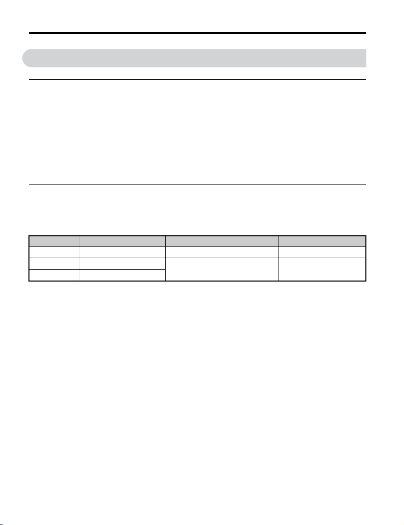
◆Contents and Packaging
Table 2 Contents of Package
◆Tools Required for Installation
• A Phillips screwdriver (M3 metric/#2 U.S. standard size <1>) is required to install the
option and remove unit front covers.
• Diagonal cutting pliers. (required for some unit models)
• A small file or medium grit sandpaper. (required for some unit models)
Description: Option Ground
Cable
Screws
(M3) LED Label Installation
Manual
–
Quantity: 11311
<1> Select a screwdriver appropriate for the unit capacity.
SI-T3
RX TX
ERR RUN
MANUAL
10 YASKAWA ELECTRIC TOBP C730600 50C YASKAWA 1000-Series Option SI-T3 Installation Manual
4 MECHATROLINK-II Option Components
4 MECHATROLINK-II Option Components
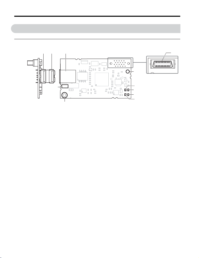
◆MECHATROLINK-II Option
Figure 1
Figure 1 Option
Note: For details on the LEDs, Refer to MECHATROLINK-II Option LED Display on page 12.
A – Connector (CN101) G – Ground terminal (installation hole)
B – Installation hole H – Model number
C – LED (ERR) I – Communication cable connector (CN3)
D – LED (RUN) J – Connector B
E – LED (TX) K – Connector A
F–LED (RX)
Looking from the connector
Underside
SI-T3
IJK
H
A
B
C
G
F
E
D

4 MECHATROLINK-II Option Components
YASKAWA ELECTRIC TOBP C730600 50C YASKAWA 1000-Series Option SI-T3 Installation Manual 11
◆Communication Connector
Table 3 Communication Connector
Note: Both connectors A and B are available for the same functions.
MECHATROLINK-II Connector Connector Pin No. Signal
Name I/O Function
A
A1 (NC) – Not used.
A2 SRD– I/O Send/receive data (–)
A3 SRD+ I/O Send/receive data (+)
A4 (NC) – Not used.
Shell SLD – Shield
B
B1 (NC) – Not used.
B2 SRD– I/O Send/receive data (–)
B3 SRD+ I/O Send/receive data (+)
B4 (NC) – Not used.
Shell SLD – Shield
A1 A2
A4
A3
B1 B2 B3 B4
CN3
4 MECHATROLINK-II Option Components
12 YASKAWA ELECTRIC TOBP C730600 50C YASKAWA 1000-Series Option SI-T3 Installation Manual
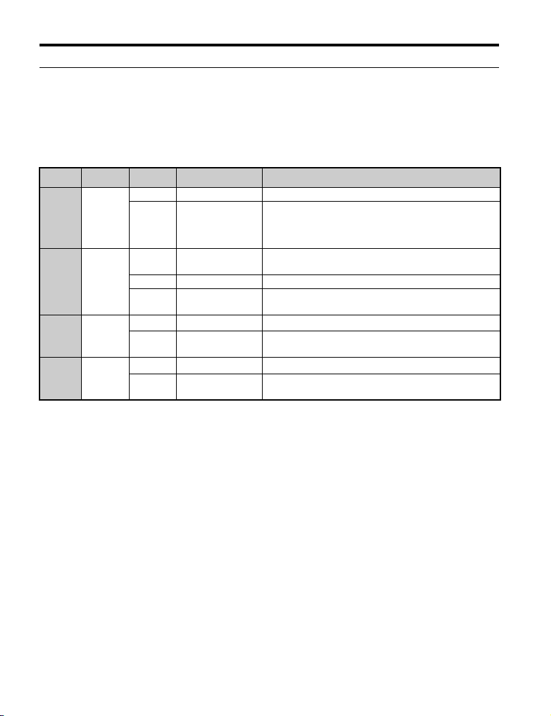
◆MECHATROLINK-II Option LED Display
The MECHATROLINK-II Option has four LEDs that indicate the option or communication
status.
■Checking LED Operation
Table 4 LED Display
LED Color Display Status Remarks
RUN Green
ON Power supply on SI-T3 has been successfully powered up
OFF No power
• The unit has no power
• SI-T3 is not properly connected to the unit, or SI-T3 has
no power
• An internal, self-diagnostic error occurred in the SI-T3
ERR Red
ON Connection error • SI-T3 is not properly connected to the unit
• Communication error
Flashing SI-T3 error Error found during SI-T3's self-diagnostic check
OFF Normal operation • SI-T3 is properly connected to the unit
• Communication normal
TX Green
ON Sending data Data is being sent (LED may appear to be flashing)
OFF Not sending data • No data is being sent
• During reset
RX Green
ON Receiving data Data is being received (LED may appear to be flashing)
OFF Not receiving data • No data is being received
• During reset

YASKAWA ELECTRIC TOBP C730600 50C YASKAWA 1000-Series Option SI-T3 Installation Manual 13
5 Installation Procedure
5 Installation Procedure
◆Section Safety
DANGER
Electric Shock Hazard
Do not connect or disconnect wiring while the power is on.
Failure to comply will result in death or serious injury.
Disconnect all power to the unit and wait at least the amount of time specified on the unit
front cover safety label.
After all indicators are off, measure the DC bus voltage to confirm safe level, and check
for unsafe voltages before servicing. The internal capacitor of the units or corresponding
parts remain charged after the power supply is turned off.
W ARNING
Electrical Shock Hazard
Do not remove the front cover of the unit while the power is on.
Failure to comply could result in death or serious injury.
The diagrams in this section may include units without covers or safety shields to show
details. Be sure to reinstall covers or shields before operating any devices. The option
board should be used according to the instructions described in this manual.
Do not allow unqualified personnel to use equipment.
Failure to comply could result in death or serious injury.
Maintenance, inspection, and replacement of parts must be performed only by authorized
personnel familiar with installation, adjustment, and maintenance of this product.
Do not touch the option while operating the unit.
Failure to comply could result in death or serious injury.

5 Installation Procedure
14 YASKAWA ELECTRIC TOBP C730600 50C YASKAWA 1000-Series Option SI-T3 Installation Manual
Do not use damaged wires, place excessive stress on wiring, or damage the wire
insulation.
Failure to comply could result in death or serious injury.
Fire Hazard
Tighten all terminal screws to the specified tightening torque.
Loose electrical connections could result in death or serious injury by fire due to
overheating of electrical connections.
NOTICE
Damage to Equipment
Observe proper electrostatic discharge (ESD) procedures when handling the option,
unit, and circuit boards.
Failure to comply may result in ESD damage to circuitry.
Never shut the power off while the unit is operating.
Failure to comply may cause the application to operate incorrectly or damage the unit.
Do not operate damaged equipment.
Failure to comply may cause further damage to the equipment.
Do not connect or operate any equipment with visible damage or missing parts.
Do not use unshielded communications cable for control wiring.
Failure to comply may cause electrical interference resulting in poor system performance.
Use shielded twisted-pair wires and ground the shield to the ground terminal of the unit.
W ARNING

5 Installation Procedure
YASKAWA ELECTRIC TOBP C730600 50C YASKAWA 1000-Series Option SI-T3 Installation Manual 15
Properly connect connectors.
Failure to comply may prevent proper operation and possibly damage equipment.
Check wiring to ensure that all connections are correct after installing the option
and connecting any other devices.
Failure to comply may result in damage to the option.
NOTICE

5 Installation Procedure
16 YASKAWA ELECTRIC TOBP C730600 50C YASKAWA 1000-Series Option SI-T3 Installation Manual
◆Prior to Installing the Option
Prior to installing the option, wire the unit, make necessary connections to the unit terminals,
and verify that the unit functions normally without the option installed. Refer to the Quick
Start Guide packaged with the unit for information on wiring and connecting the unit.
Figure 2 shows an exploded view of the unit with the option and related components for
reference.
Figure 2
Figure 2 Unit Components with Option
A – Insertion point for CN101 connector H – Included screws
B – SI-T3 option I – Ground wire
C – Unit front cover J – Option modular connector CN3
D – Digital operator K – Unit grounding terminal (FE)
E – LED label L – Connector CN5-A
F – Unit terminal cover M – Connector CN5-B
(Not available for the option.)
G – Removable tabs for wire routing N – Connector CN5-C
(Not available for the option.)
F
H
L
M
N
K
I
BC
D
E
A
G
NS
TXRX
ERR RUN
J

5 Installation Procedure
YASKAWA ELECTRIC TOBP C730600 50C YASKAWA 1000-Series Option SI-T3 Installation Manual 17
◆Installing the Option
Remove the front covers of the unit before installing the option. Refer to the unit instruction
manual for directions on removing the front covers. Cover removal varies depending on unit
size. This option can be inserted only into the
CN5-A connector located on the unit control board.
DANGER! Electrical Shock Hazard. Disconnect all power to the unit and wait at
least the amount of time specified on the unit front cover safety label. After all
indicators are off, measure the DC bus voltage to confirm safe level, and check for
unsafe voltages before servicing to prevent electric shock. The internal capacitor
remains charged even after the power supply is turned off.
1. Shut off power to the unit, wait the appropriate amount of time for voltage to
dissipate, then remove the digital operator (D) and front covers (C, F). Front cover
removal varies by model.
NOTICE: Damage to Equipment. Observe proper electrostatic discharge (ESD) procedures when handling
the option, unit, and circuit boards. Failure to comply may result in ESD damage to circuitry.
Figure 3
Figure 3 Remove the Front Covers and Digital Operator
C
D
F

5 Installation Procedure
18 YASKAWA ELECTRIC TOBP C730600 50C YASKAWA 1000-Series Option SI-T3 Installation Manual
2. With the front covers and digital operator removed, apply the LED label (E) in the
appropriate position on the unit top front cover (C).
Figure 4
Figure 4 Apply the LED Label
3. Insert the option (B) into the CN5-A connector (L) located on the unit and fasten it
using one of the included screws (H).
Figure 5
Figure 5 Insert the Option
TXRX
ERR RUN
C
E
NS MS
L
H
B

5 Installation Procedure
YASKAWA ELECTRIC TOBP C730600 50C YASKAWA 1000-Series Option SI-T3 Installation Manual 19
4. Connect the ground wire (I) to the ground terminal (K) using one of the remaining
provided screws (H). Connect the other end of the ground wire (I) to the remaining
ground terminal and installation hole on the option (B) using the last remaining
provided screw (H) and tighten both screws to 0.5 to 0.6 Nxm (4.4 to 5.3 in lbs).
Figure 6
Figure 6 Connect the Ground Wire
Note: There are two screw holes on the unit for use as ground terminals (K). When connecting three
options, two ground wires will need to share the same unit ground terminal.
Figure 7
Figure 7 Connecting the Ground Terminal
H
I
K
B
SI-T3

5 Installation Procedure
20 YASKAWA ELECTRIC TOBP C730600 50C YASKAWA 1000-Series Option SI-T3 Installation Manual
5. Route the option wiring.
Depending on the unit model, some unit may require routing the wiring through the
side of the front cover to the outside to provide adequate space for the wiring. Refer
to the Peripheral Devices & Options section of the unit instruction manual for more
information on wire routing of specific models.
Route the wiring through the side of the front cover to the outside. In these cases,
using diagonal cutting pliers, cut out the perforated openings on the left side of the
unit front cover as shown in Figure 8-A. Sharp edges along the cut out should be
smoothed down with a file or sand paper to prevent any damage to the wires.
Route the wiring inside the enclosure as shown in Figure 8-B for units that do not
require routing through the front cover.
Note: 1. Separate communication cables from main circuit wiring and other electrical lines.
2. Connect the terminator (model No.: JEPMC-W6022-E) to the option modular connector (CN3) on the
end unit of the communication lines.
Figure 8
Figure 8 Wire Routing Examples
B
A
Other manuals for SI-T3 MECHATROLINK-II A1000 Series
3
This manual suits for next models
2
Table of contents
Other YASKAWA Inverter Drive manuals


