YASKAWA DeviceNet SI-N3 User manual
MANUAL NO. TOEP C730600 84A
YASKAWA AC Drive Option
DeviceNet
Installation Manual
Model SI-N3
To correctly use the product, read this manual thoroughly and keep it
for easy reference, inspection, and maintenance. Make sure that the
end user receives this manual.

This Page Intentionally Blank
2YASKAWA TOEP C730600 84A DeviceNet Installation Manual

YASKAWA TOEP C730600 84A DeviceNet Installation Manual 3
Table of Contents
1. Preface and Safety. . . . . . . . . . . . . . . . . . . . . . . . . . . . . . . . . . . . . . . . . . . . 5
Applicable Documentation . . . . . . . . . . . . . . . . . . . . . . . . . . . . . . . . . . . . . . . . . . . . . 6
Glossary . . . . . . . . . . . . . . . . . . . . . . . . . . . . . . . . . . . . . . . . . . . . . . . . . . . . . . . . . . . . 6
Registered Trademarks . . . . . . . . . . . . . . . . . . . . . . . . . . . . . . . . . . . . . . . . . . . . . . . . 7
Supplemental Safety Information . . . . . . . . . . . . . . . . . . . . . . . . . . . . . . . . . . . . . . . . 7
Section Safety . . . . . . . . . . . . . . . . . . . . . . . . . . . . . . . . . . . . . . . . . . . . . . . . . . . 7
2. Overview . . . . . . . . . . . . . . . . . . . . . . . . . . . . . . . . . . . . . . . . . . . . . . . . . . . . 8
Compatible Products . . . . . . . . . . . . . . . . . . . . . . . . . . . . . . . . . . . . . . . . . . . . . . . . . . 8
Install the Option on a GA500 Drive . . . . . . . . . . . . . . . . . . . . . . . . . . . . . . . . . . . . . . 9
3. Receiving . . . . . . . . . . . . . . . . . . . . . . . . . . . . . . . . . . . . . . . . . . . . . . . . . . 10
Option Package Contents . . . . . . . . . . . . . . . . . . . . . . . . . . . . . . . . . . . . . . . . . . . . . .11
Installation Tools . . . . . . . . . . . . . . . . . . . . . . . . . . . . . . . . . . . . . . . . . . . . . . . . . . . . .11
4. Option Components . . . . . . . . . . . . . . . . . . . . . . . . . . . . . . . . . . . . . . . . . . 12
Option . . . . . . . . . . . . . . . . . . . . . . . . . . . . . . . . . . . . . . . . . . . . . . . . . . . . . . . . . . . . . 12
Terminal block CN1 . . . . . . . . . . . . . . . . . . . . . . . . . . . . . . . . . . . . . . . . . . . . . . . . . . 12
Option LED Display . . . . . . . . . . . . . . . . . . . . . . . . . . . . . . . . . . . . . . . . . . . . . . . . . . 13
Power-Up Diagnostics . . . . . . . . . . . . . . . . . . . . . . . . . . . . . . . . . . . . . . . . . . . . 15
5. Installation Procedure . . . . . . . . . . . . . . . . . . . . . . . . . . . . . . . . . . . . . . . . 15
Section Safety . . . . . . . . . . . . . . . . . . . . . . . . . . . . . . . . . . . . . . . . . . . . . . . . . . . . . . 15
Procedures to Install and Wire Options on a Drive . . . . . . . . . . . . . . . . . . . . . . . . . 16
Procedure A . . . . . . . . . . . . . . . . . . . . . . . . . . . . . . . . . . . . . . . . . . . . . . . . . . . . 17
Procedure B . . . . . . . . . . . . . . . . . . . . . . . . . . . . . . . . . . . . . . . . . . . . . . . . . . . . 21
Procedure C . . . . . . . . . . . . . . . . . . . . . . . . . . . . . . . . . . . . . . . . . . . . . . . . . . . . 27
Procedure D . . . . . . . . . . . . . . . . . . . . . . . . . . . . . . . . . . . . . . . . . . . . . . . . . . . . 32
Option Connection Diagram . . . . . . . . . . . . . . . . . . . . . . . . . . . . . . . . . . . . . . . . . . . 41

4YASKAWA TOEP C730600 84A DeviceNet Installation Manual
Communication Cable Wiring . . . . . . . . . . . . . . . . . . . . . . . . . . . . . . . . . . . . . . . . . . . 41
Termination Resistor Connection . . . . . . . . . . . . . . . . . . . . . . . . . . . . . . . . . . . . . . . . 43
Option MAC ID . . . . . . . . . . . . . . . . . . . . . . . . . . . . . . . . . . . . . . . . . . . . . . . . . . . . . . . 43
Parameter F6-50 [DeviceNet MAC Address] (MAC ID Setting) . . . . . . . . . . . . 43
Communication Speed . . . . . . . . . . . . . . . . . . . . . . . . . . . . . . . . . . . . . . . . . . . . . . . . 43
Auto Baud Rate Sensing (F6-51 = 4 [DeviceNet Baud Rate = Detect
Automatically]) . . . . . . . . . . . . . . . . . . . . . . . . . . . . . . . . . . . . . . . . . . . . . . . . . . . 43
EDS Files . . . . . . . . . . . . . . . . . . . . . . . . . . . . . . . . . . . . . . . . . . . . . . . . . . . . . . . . . . . 43
6. Related Drive Parameters . . . . . . . . . . . . . . . . . . . . . . . . . . . . . . . . . . . . . . 44
7. Configuring DeviceNet Messaging . . . . . . . . . . . . . . . . . . . . . . . . . . . . . . . 50
Drive Polled Configuration on DeviceNet . . . . . . . . . . . . . . . . . . . . . . . . . . . . . . . . . . 50
Drive Operation on DeviceNet . . . . . . . . . . . . . . . . . . . . . . . . . . . . . . . . . . . . . . . . . . 53
Polled Assemblies Quick Reference . . . . . . . . . . . . . . . . . . . . . . . . . . . . . . . . . 53
Output Assemblies/Drive Consumes . . . . . . . . . . . . . . . . . . . . . . . . . . . . . . . . . 53
Input Assemblies/Drive Produces. . . . . . . . . . . . . . . . . . . . . . . . . . . . . . . . . . . . 53
8. Troubleshooting . . . . . . . . . . . . . . . . . . . . . . . . . . . . . . . . . . . . . . . . . . . . . . 54
Drive-Side Error Codes . . . . . . . . . . . . . . . . . . . . . . . . . . . . . . . . . . . . . . . . . . . . . . . . 54
Fault . . . . . . . . . . . . . . . . . . . . . . . . . . . . . . . . . . . . . . . . . . . . . . . . . . . . . . . . . . . 54
Minor Faults and Alarms . . . . . . . . . . . . . . . . . . . . . . . . . . . . . . . . . . . . . . . . . . . 56
Option Compatibility. . . . . . . . . . . . . . . . . . . . . . . . . . . . . . . . . . . . . . . . . . . . . . . . . . . 56
9. Trunk Line and Drop Line Length . . . . . . . . . . . . . . . . . . . . . . . . . . . . . . . . 57
Trunk Line. . . . . . . . . . . . . . . . . . . . . . . . . . . . . . . . . . . . . . . . . . . . . . . . . . . . . . . . . . . 57
Drop Line . . . . . . . . . . . . . . . . . . . . . . . . . . . . . . . . . . . . . . . . . . . . . . . . . . . . . . . . . . . 58
10. European Standards . . . . . . . . . . . . . . . . . . . . . . . . . . . . . . . . . . . . . . . . . . 58
EMC Directive Compliance . . . . . . . . . . . . . . . . . . . . . . . . . . . . . . . . . . . . . . . . . . . . . 58
Option Installation . . . . . . . . . . . . . . . . . . . . . . . . . . . . . . . . . . . . . . . . . . . . . . . . . . . . 59
11. Specifications . . . . . . . . . . . . . . . . . . . . . . . . . . . . . . . . . . . . . . . . . . . . . . . . 61
Specifications . . . . . . . . . . . . . . . . . . . . . . . . . . . . . . . . . . . . . . . . . . . . . . . . . . . . . . . . 61
12. Disposal . . . . . . . . . . . . . . . . . . . . . . . . . . . . . . . . . . . . . . . . . . . . . . . . . . . . 62
Disposal Instructions . . . . . . . . . . . . . . . . . . . . . . . . . . . . . . . . . . . . . . . . . . . . . . . . . . 62
WEEE Directive . . . . . . . . . . . . . . . . . . . . . . . . . . . . . . . . . . . . . . . . . . . . . . . . . . . . . . 62
Revision History . . . . . . . . . . . . . . . . . . . . . . . . . . . . . . . . . . . . . . . . . . . . . . . . . . 64

1 Preface and Safety
YASKAWA TOEP C730600 84A DeviceNet Installation Manual 5
1 Preface and Safety
YASKAWA Electric supplies component parts for use in a wide variety of industrial
applications. The selection and application of YASKAWA products remain the
responsibility of the equipment designer or end user.
YASKAWA accepts no responsibility for the way its products are incorporated into the
final system design. Under no circumstances should any YASKAWA product be
incorporated into any product or design as the exclusive or sole safety control. Without
exception, all controls should be designed to detect faults dynamically and fail safely
under all circumstances. All products designed to incorporate a component part
manufactured by YASKAWA must be supplied to the end user with appropriate warnings
and instructions as to the safe use and operation of that part. Any warnings provided by
YASKAWA must be promptly provided to the end user. YASKAWA offers an express
warranty only as to the quality of its products in conforming to standards and
specifications published in the manual. NO OTHER WARRANTY, EXPRESS OR
IMPLIED, IS OFFERED. YASKAWA assumes no liability for any personal injury,
property damage, losses, or claims arising from misapplication of its products.
1 Preface and Safety
6YASKAWA TOEP C730600 84A DeviceNet Installation Manual
◆Applicable Documentation
Document Description
YASKAWA AC Drive Option
DeviceNet
Installation Manual
(This book)
Read this manual first.
The manual provides information about wiring, settings, functions, and
troubleshooting. The manual is packaged together with the product.
YASKAWA AC Drive Option
DeviceNet
Technical Manual
Manual No.: SIEP C730600 84
The technical manual contains detailed information about the option.
Access the following sites to obtain the technical manual:
U.S.: http://www.yaskawa.com
Europe: http://www.yaskawa.eu.com
Japan: http://www.e-mechatronics.com
Other areas: Check the back cover of these manuals.
For questions, contact Yaskawa or a Yaskawa representative.
YASKAWA AC Drive
Manuals
Refer to the drive manual to connect with the option.
Drive manuals contain basic installation and wiring information in
addition to detailed parameter setting, fault diagnostic, and maintenance
information.
The manuals also include important information about parameter settings
and tuning the drive.
The Quick Start Guides are packaged with the drive.
The most recent versions of these manuals are available for download on
our documentation websites:
U.S.: http://www.yaskawa.com
Europe: http://www.yaskawa.eu.com
Japan: http://www.e-mechatronics.com
Other areas: Check the back cover of these manuals.
For questions, contact Yaskawa or a Yaskawa representative.
◆Glossary
Terms Definition
Option YASKAWA AC Drive Option SI-N3 DeviceNet
Keypad
•LCD Operator
•LED Operator
•LCD Keypad
•LED Keypad
Hex. (Example: 900
(Hex.))
Identifies a unit for hexadecimal number format.
1 Preface and Safety
YASKAWA TOEP C730600 84A DeviceNet Installation Manual 7
◆Registered Trademarks
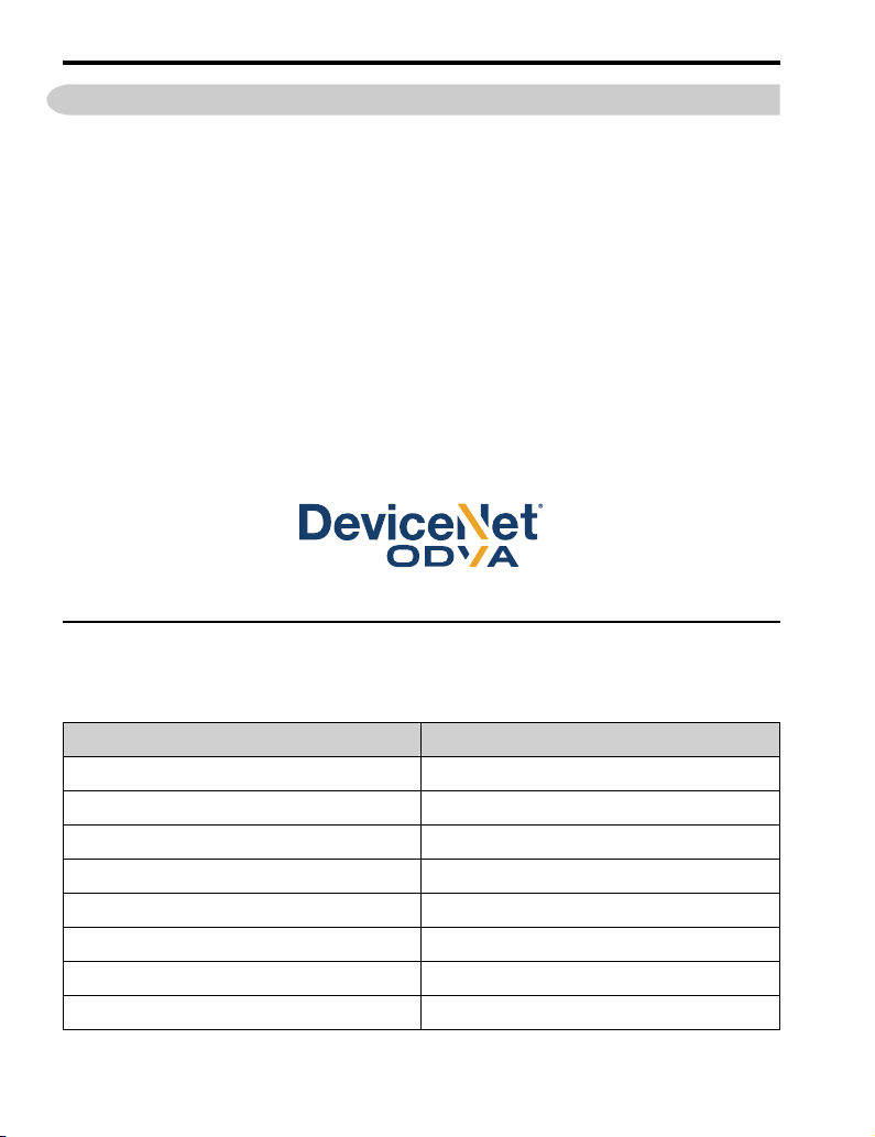
•DeviceNet is a registered trademark of Open DeviceNet Vendor Association, Inc.
(ODVA).
•Trademarks are the property of their respective owners.
◆Supplemental Safety Information
Read and understand this manual before installing, operating, or servicing this option. The
option must be installed according to this manual and local codes.
The following conventions are used to indicate safety messages in this manual. Failure to
heed these messages could result in serious or possibly even fatal injury or damage to the
products or to related equipment and systems.
DANGER This signal word identifies a hazard that will cause serious injury or death if you do
not prevent it.
WARNING This signal word identifies a hazard that can cause death or serious injuries if you
do not prevent it.
CAUTION This signal word identifies a hazardous situation, which, if not avoided, can cause
minor or moderate injury.
NOTICE This signal word identifies a property damage message that is not related to
personal injury.
■Section Safety
General Precautions
•The diagrams in this section may include options and drives without covers or safety shields to illustrate
details. Be sure to reinstall covers or shields before operating any devices. The option should be used
according to the instructions described in this manual.
•The diagrams in this manual are provided as examples only and may not pertain to all products covered by this
manual.
•The products and specifications described in this manual or the content and presentation of the manual may be
changed without notice to improve the product and/or the manual.
•Contact Yaskawa or a Yaskawa representative and provide the manual number shown on the front cover to
order new copies of the manual.
DANGER Do not ignore the safety messages in this manual. If you ignore the safety
messages in this manual, it will cause serious injury or death. The manufacturer is not responsible for
injuries or damage to equipment.
WARNING Electrical Shock Hazard. Do not modify the drive or option circuitry. Failure to obey
can cause serious injury or death, or cause damage to the drive or option and will void warranty. Yaskawa
is not responsible for modifications of the product made by the user.
NOTICE Damage to Equipment. Do not use steam or other disinfectants to fumigate wood
for packaging the drive. Use alternative methods, for example heat treatment, before you package the
components. Gas from wood packaging fumigated with halogen disinfectants, for example fluorine,
chlorine, bromine, iodine or DOP gas (phthalic acid ester), can cause damage to the drive.
2 Overview
8YASKAWA TOEP C730600 84A DeviceNet Installation Manual
2 Overview
This option provides a communications connection between the drive and an ODVA
DeviceNet network. The option connects the drive to a DeviceNet network and facilitates
the exchange of data.
DeviceNet is a communications link to connect industrial devices (for example limit
switches, photoelectric switches, motor starters, smart motor controllers, operator
interfaces, and variable frequency drives) and control devices (for example,
programmable controllers and computers) to a network. DeviceNet is a simple networking
solution. DeviceNet decreases the cost and time to wire and install factory automation
devices, and it gives the option to interchange like components from other vendors.
DeviceNet is an open network standard.
Install the option/DeviceNet option on a drive to do these functions from a DeviceNet
communication master device:
•Operate the drive
•Monitor the drive operation status
•Change drive parameter settings
Figure 2.1 DeviceNet Approved
◆Compatible Products
You can use the option with these products:
Table 2.1 Compatible Products
Drive Model
A1000 All
E1000 All
H1000 All
L1000A *1 All
U1000 *1 All
Z1000U *1 All
Z1000 All
GA500 All

2 Overview
YASKAWA TOEP C730600 84A DeviceNet Installation Manual 9
Drive Model
GA700 *2 All
GA800 *2 All
FP605 *2 All
*1 Before you install the option on an L1000A, U1000 or Z1000U drive, make sure that the option software
version is PRG: 1112 or later.
*2 Before you install the option on a GA500, GA700, GA800, or FP605 drive, make sure that the option
software version is PRG: 1115 or later.
Note:
•Refer to the option package labeling in the field designated “PRG (four digit number)”or the option labeling in
the field to identify the option software version.
•For Yaskawa customers in the North or South America region:
If your product is not listed in Table 2.1, refer to the web page below to confirm this manual is correct for your
product. The web page provides a list of option manuals by product, and a direct link to download a PDF of
the manual.
Scan QR code Or refer to:
http://www.yaskawa.com/optionlookup
◆Install the Option on a GA500 Drive
An option card mounting kit is necessary to install the option on a GA500 drive. The
option card mounting kit model is: JOHB-GA50. This kit is sold separately.
Refer to the option card mounting kit manual for more information about installation.
3 Receiving
10 YASKAWA TOEP C730600 84A DeviceNet Installation Manual
A - Option card mounting kit
components (sold separately)
B - Option
C - Drive front cover
Figure 2.2 Option Card Mounting Kit (JOHB-GA50)
3 Receiving
After you receive the option package:
•Make sure that there is no damage to the option and no parts are missing.
The Yaskawa warranty does not include damage from shipping. If there is damage to
the option or other parts, contact the shipping company immediately.
NOTICE Damage to Equipment. Do not use damaged parts to connect the drive and the
option. Failure to comply could damage the drive and option.
•Make sure that the model number on the option nameplate and the model number on
the purchase order are the same. Refer to Figure 4.1 for more information.
•Contact the distributor where you purchased the option or contact Yaskawa or a
Yaskawa representative about any problems with the option.

3 Receiving
YASKAWA TOEP C730600 84A DeviceNet Installation Manual 11
◆Option Package Contents
Table 3.1 Contents of Package
Option Contents Quantity
Option 1
Ground wire *1 1
Screws (M3) 3 *2
LED label
1000-Series, Z1000U 1
GA500, GA700, and
GA800 1
Z1000, FP605 *3 1*4
Manuals 1
*1 GA700 and GA800 drives do not use the ground wire.
*2 Only two screws are necessary to install the option on GA700 and GA800 drives.
*3 LED label has transparent background and white letters. Please make sure that you use the correct label for
Z1000 or FP605.
*4 Options purchased in Japan do not include LED labels for Z1000 or FP605.
◆Installation Tools
You can use these tools to install the option to the drive:
4 Option Components
12 YASKAWA TOEP C730600 84A DeviceNet Installation Manual
•A Phillips screwdriver or slotted screwdriver (M3 *1)
•A flat-blade screwdriver (blade depth: 0.4 mm (0.02 in.), width: 2.5 mm (0.1 in.)).
•A pair of diagonal cutting pliers.
•A small file or medium-grit sandpaper.
*1 Phillips screw sizes are different for different drive capacities. Prepare different
screwdrivers for different screw sizes.
4 Option Components
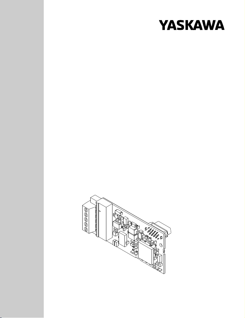
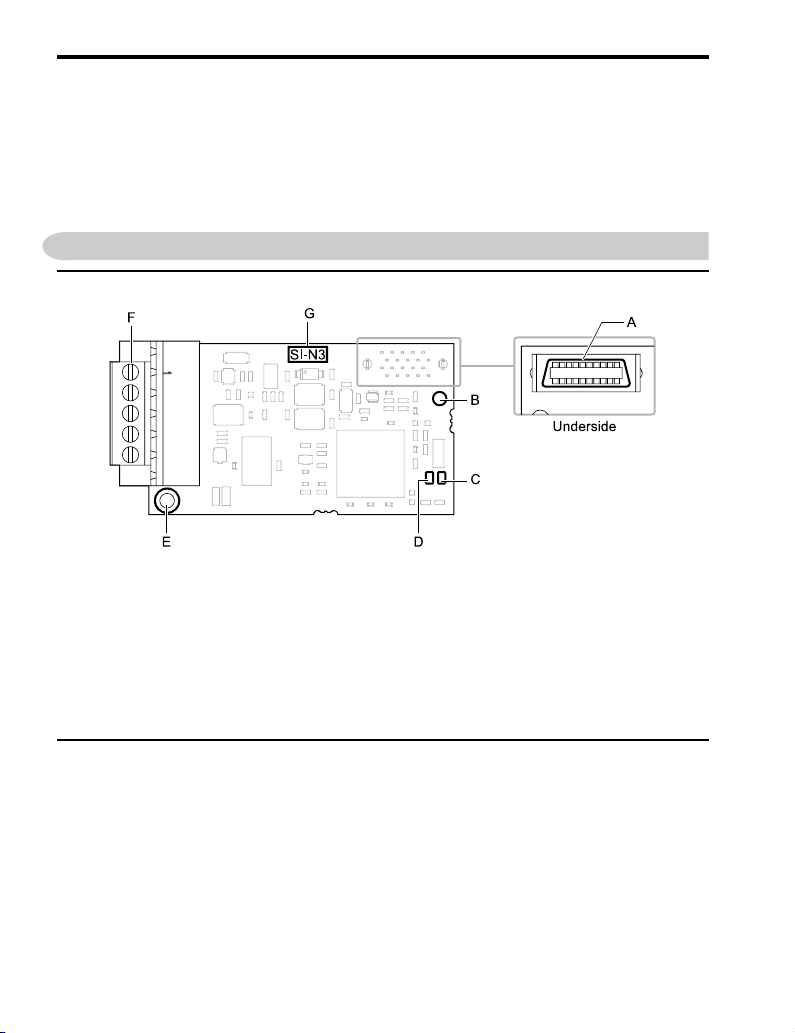
◆Option
A - Connector (CN5)
B - Installation hole
C - LED (MS) *1
D - LED (NS) *1
E - Ground terminal (FE) and
installation hole *2
F - Terminal block CN1
G - Option model number
Figure 4.1 Option
*1 Refer to Option LED Display on page 13 for more information about the LEDs.
*2 Connect the included ground wire during installation. The ground wire is not necessary for installation on
GA700 and GA800 drives.
◆Terminal block CN1
The communication terminal is a pluggable terminal block that serves as the connection
point of the DeviceNet network communication cable to the option.

4 Option Components
YASKAWA TOEP C730600 84A DeviceNet Installation Manual 13
Table 4.1 Terminal Descriptions
Terminal Pin Color Signal Description
1 Black V- Network common
2 Blue CAN_L CAN data Low
3 - Shield Cable shield
4 White CAN_H CAN data High
5 Red V+
Communications
network power DC
+24V
◆Option LED Display
The option has two bicolor LEDs:
•Module status (MS)
•Network status (NS)
A - 1000-Series, Z1000U
B - GA500, GA700, and GA800
C - Z1000, FP605 *1
Figure 4.2 Option LED Labels
*1 LED label has transparent background and white letters. Please make sure that you use the correct label for
Z1000 or FP605.
Wait 2 seconds minimum for the power-up diagnostic process to complete before you
verify the LED states.
The operational status of the option LEDs after the power-up diagnostic LED sequence is
complete are described in Table 4.2.
Refer to Table 4.3 for more information about the LEDs.
Table 4.2 Option LED States
LED Name
Indication
Operating State Description
Color Dis
play
MS OFF Power supply OFF There is no power to the drive.

4 Option Components
14 YASKAWA TOEP C730600 84A DeviceNet Installation Manual
LED Name
Indication
Operating State Description
Color Dis
play
Green ON Option operating The option is operating normally.
Green Flash
ing Option initializing
There are defects or errors in the settings.
•There is an incorrect baud rate setting.
•MAC ID duplication
Red ON Fatal error occurred
The option detected a fatal (unrecoverable) error.
If the unit does not recover after you cycle
power, you may need to replace the option.
Red Flash
ing
Non-fatal error
occurred
The option detected a non-fatal (recoverable)
error.
Red/
Green
Flash
ing Option self-test The option is in self-test mode.
NS
OFF Power supply OFF or
Offline
The drive is not on-line.
•Duplicate MAC ID test has not been passed.
•There is no power to the drive.
Green ON
Online
communications
established
The option is online and has established
connections.
•The option has established connections to
other nodes.
Green Flash
ing
Online
communications not
established
The option is online without an established
connection.
•Duplicate MAC ID test was passed and is
online but has no open connections to other
nodes.
Red ON Ring fault
The option detected a communications device
error.
•An error occurred disabling DeviceNet
communications. (MAC ID duplication or
Bus off detected)
Red Flash
ing
Communications time-
out (non-fatal) A communications time-out occurred.
Red/
Green
Flash
ing Comm error
Specific communication faulted device.
•The device detected a network access error
and is in the communications faulted state.
•The device then received and accepted an
Identify communication fault request-long
protocol message.
5 Installation Procedure
YASKAWA TOEP C730600 84A DeviceNet Installation Manual 15
■Power-Up Diagnostics
An LED test is performed each time the drive is powered up. The initial boot sequence
can take several seconds. After the LEDs complete the diagnostic LED sequence, the
option is successfully initialized. The LEDs then assume operational conditions as shown
in Table 4.2.
Table 4.3 Power-Up Diagnostic LED Sequence
Sequence Module Status (MS) Network Status (NS) Time (ms)
1 Green OFF 250
2 Red OFF 250
3 Green Green 250
4 Green Red 250
5 Green OFF -
5 Installation Procedure
◆Section Safety
DANGER Electrical Shock Hazard. Do not examine, connect, or disconnect wiring on an
energized drive. Before servicing, disconnect all power to the equipment and wait for the time specified on
the warning label at a minimum. The internal capacitor stays charged after the drive is de-energized. The
charge indicator LED extinguishes when the DC bus voltage decreases below 50 Vdc. When all indicators
are OFF, measure for dangerous voltages to make sure that the drive is safe. If you do work on the drive
when it is energized, it will cause serious injury or death from electrical shock.
WARNING Electrical Shock Hazard. Do not operate the drive when covers are missing.
Replace covers and shields before you operate the drive. Use the drive only as specified by the
instructions. Some figures in this section include drives without covers or safety shields to more clearly
show the inside of the drive. If covers or safety shields are missing from the drive, it can cause serious
injury or death.
WARNING Electrical Shock Hazard. Only let approved personnel install, wire, maintain,
examine, replace parts, and repair the drive. If personnel are not approved, it can cause serious injury or
death.
WARNING Electrical Shock Hazard. Do not remove covers or touch circuit boards while the
drive is energized. If you touch the internal components of an energized drive, it can cause serious injury
or death.
WARNING Electrical Shock Hazard. Do not use damaged wires, put too much force on the
wiring, or cause damage to the wire insulation. Damaged wires can cause serious injury or death.
WARNING Fire Hazard. Tighten all terminal screws to the correct tightening torque.
Connections that are too loose or too tight can cause incorrect operation and damage to the drive.
Incorrect connections can also cause death or serious injury from fire.

5 Installation Procedure
16 YASKAWA TOEP C730600 84A DeviceNet Installation Manual
NOTICE Damage to Equipment. When you touch the option, make sure that you observe
correct electrostatic discharge (ESD) procedures. If you do not follow procedures, it can cause ESD
damage to the drive circuitry.
NOTICE Damage to Equipment. Do not de-energize the drive while the drive is outputting
voltage. Incorrect equipment sequencing can cause damage to the drive.
NOTICE Do not operate a drive or connected equipment that has damaged or missing parts.
You can cause damage to the drive and connected equipment.
NOTICE Use Yaskawa connection cables or recommended cables only. Incorrect cables
can cause the drive or option to function incorrectly.
NOTICE Damage to Equipment. Correctly connect the connectors. Incorrect connections
can cause malfunction or damage to the equipment.
NOTICE Damage to Equipment. Make sure that all connections are correct after you install
the drive and connecting peripheral devices. Incorrect connections can cause damage to the option.
◆Procedures to Install and Wire Options on a Drive
Procedures to install and wire the option are different for different drive models.
Refer to the following table to check the procedures to install and wire the option on a
drive.
Table 5.1 Procedures to Install and Wire Options on a Drive
Drive Procedures to Install and Wire
Options on a Drive Reference Page
A1000 Procedure A 17
E1000 Procedure A 17
H1000 Procedure A 17
L1000A Procedure A 17
U1000 Procedure A 17
Z1000U Procedure A 17
Z1000 Procedure B 21
GA500 *1 *2 -
GA700 Procedure C 27
GA800 Procedure C 27
FP605 Procedure D 32
*1 To install the option on GA500 drives, use the option mounting kit (JOHB-GA50) and manual.
*2 Before you install the option on a GA500 drive, make sure that the option software version is PRG: 1115 or
later.
5 Installation Procedure
YASKAWA TOEP C730600 84A DeviceNet Installation Manual 17
■Procedure A
This section shows the procedure to install and wire the option on a 1000-series drive.
Prepare the Drive for the Option
Before you install the option on a YASKAWA AC Drive L1000A, U1000 or Z1000U,
make sure that the option software version is PRG: 1112 or later.
Correctly wire the drive as specified by the manual packaged with the drive. Make sure
that the drive functions correctly. Refer to the drive manuals for more information.
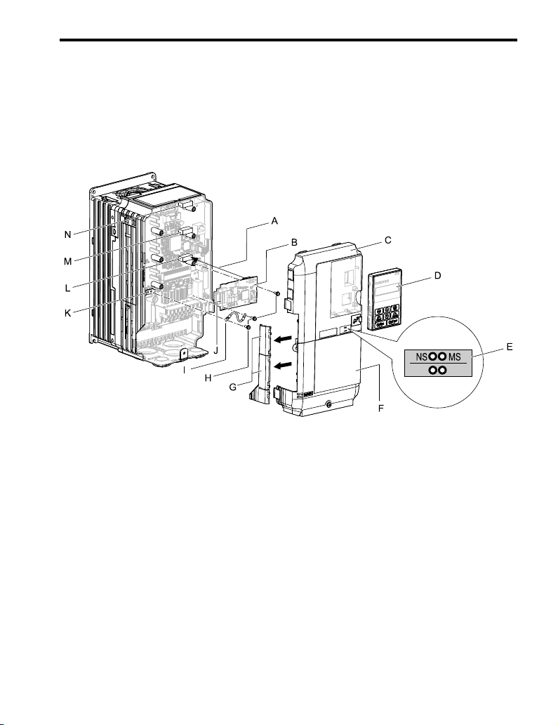
A - Insertion point for CN5 connector
B - Option
C - Drive front cover
D - Keypad
E - LED label
F - Drive terminal cover
G - Removable tabs for wire routing
H - Included screws
I - Ground wire
J - Terminal block (CN1)
K - Drive grounding terminal (FE)
L - Connector CN5-A
M - Connector CN5-B (Not available
for communication option
installation.)
N - Connector CN5-C (Not available
for communication option
installation.)
Figure 5.1 Drive Components with Option
Install the Option
Use this procedure to install the option.

5 Installation Procedure
18 YASKAWA TOEP C730600 84A DeviceNet Installation Manual
DANGER Electrical Shock Hazard. Do not examine, connect, or disconnect wiring on an
energized drive. Before servicing, disconnect all power to the equipment and wait for the time specified on
the warning label at a minimum. The internal capacitor stays charged after the drive is de-energized. The
charge indicator LED extinguishes when the DC bus voltage decreases below 50 Vdc. When all indicators
are OFF, measure for dangerous voltages to make sure that the drive is safe. If you do work on the drive
when it is energized, it will cause serious injury or death from electrical shock.
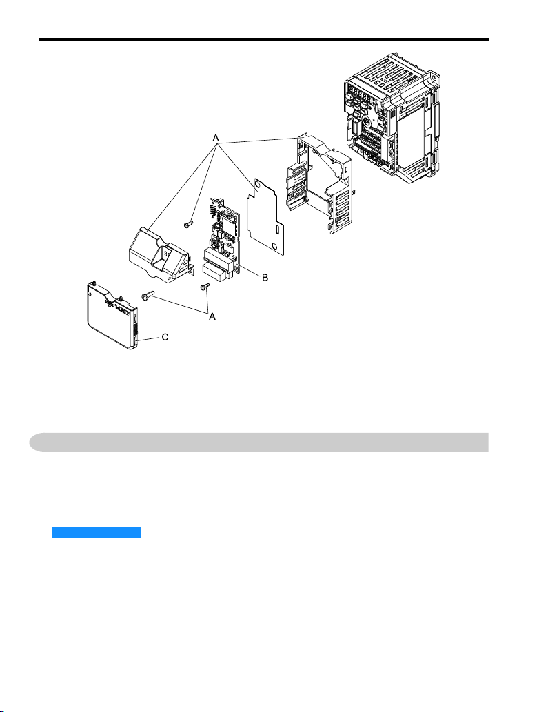
1. Remove the keypad (B), front cover (A), and terminal cover (C).
Shut off power to the drive and wait for the time specified on the drive warning
label at a minimum. Make sure that the charge indicator LED is unlit, then remove
the keypad and front cover. Refer to the drive manuals for more information.
You can only install this option into the CN5-A connector on the drive control
board.
NOTICE Damage to Equipment. When you touch the option, make sure that
you observe correct electrostatic discharge (ESD) procedures. If you do not follow
procedures, it can cause ESD damage to the drive circuitry.
A - Drive front cover
B - Keypad
C - Drive terminal cover
Figure 5.2 Remove the Keypad, Front Cover, and Terminal Cover

5 Installation Procedure
YASKAWA TOEP C730600 84A DeviceNet Installation Manual 19
2. Put the LED label (B) in the correct position on the drive front cover (A).
A - Drive front cover B - LED label
Figure 5.3 Put the LED Label on the Drive Front Cover
3. Install the option (A) into the CN5-A connector (C) on the drive and use the
included screws (B) to put it in place.
A - Option
B - Included screw
C - Connector CN5-A
Figure 5.4 Install the Option
5 Installation Procedure
20 YASKAWA TOEP C730600 84A DeviceNet Installation Manual
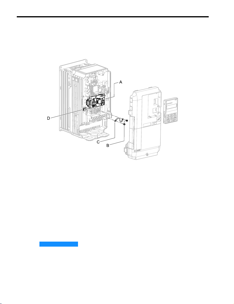
4. Use one of the remaining included screws (B) to connect one end of the ground
wire (C) to the ground terminal (D). Use the last remaining included screw (B) to
connect the other end of the ground wire (C) to the remaining ground terminal and
installation hole on the option (A).
Tighten the screws to a correct tightening torque:
• 0.5 N∙m to 0.6 N∙m (4.4 in∙lb to 5.3 in∙lb)
A - Option
B - Included screws
C - Ground wire
D - Drive grounding terminal (FE)
Figure 5.5 Connect the Ground Wire
Note:
The drive has only two ground terminal screw holes. When you connect three options, two options will
share one ground terminal.
5. Route the option wiring.
Procedures to wire the option are different for different drive models.
Firmly connect the DeviceNet communication cable to option terminal block
(CN1). Isolate communication cables from main circuit wiring and other electrical
and power lines. Refer to Communication Cable Wiring on page 41 for more
information.
NOTICE Damage to Equipment. When you touch the option, make sure that
you observe correct electrostatic discharge (ESD) procedures. If you do not follow
procedures, it can cause ESD damage to the drive circuitry.
6. Reattach the front cover (A), terminal cover (C), and keypad (B).
Refer to the drive manuals for more information.
Other manuals for DeviceNet SI-N3
4
Table of contents
Other YASKAWA Inverter Drive manuals


