Yeasn SLY-100 User manual

SLY-100
Vision Tester
User Manual
Version: 1.2
Revision Date: 2022.06

Product Name: Vision Tester
Nome do produto: Testador de visão
Nombre del producto: Probador de visión
Ürün Adı: Görme test cihazı
Nome prodotto: Tester della vista
Produktname: Sehtester
Nom du produit : Testeur de vision
Име на продукта: Тестер за зрение
Produkto pavadinimas: Foropteris
Nazwa produktu: Tester wizji
Název produktu: Tester zraku
Toote nimi: Nägemistestija
Produkta nosaukums: Redzes pārbaudītājs
Όνομα προϊόντος: Ελεγκτής όρασης
User Manual Download link: www.yeasn.com/en/
Link para download do manual do usuário: www.yeasn.com/en/
Manual de usuario Enlace de descarga: www.yeasn.com/en/
Kullanım Kılavuzu İndirme linki: www.yeasn.com/en/
Manuale d'uso Link per il download: www.yeasn.com/en/
Link zum Herunterladen des Benutzerhandbuchs: www.yeasn.com/en/
Lien de téléchargement du manuel d'utilisation : www.yeasn.com/en/
Линк за изтегляне на ръководството за потребителя: www.yeasn.com/en/
Naudotojo vadovo atsisiuntimo nuoroda: www.yeasn.com/en/
Link do pobrania instrukcji obsługi: www.yeasn.com/en/
Uživatelská příručka Odkaz ke stažení: www.yeasn.com/en/
Kasutusjuhendi allalaadimise link: www.yeasn.com/en/
Lietotāja rokasgrāmatas lejupielādes saite: www.yeasn.com/en/
Εγχειρίδιο χρήστη Σύνδεσμος λήψης: www.yeasn.com/en/

Preface
Thanks for purchasing and using SLY-100 vision tester.
Please read this User Manual carefully before using this device. We sincerely
hope that this User Manual will provide you with sufficient information to use the
device.
Our pursuit is to provide people with high-quality, complete-function and more
personalized devices. Information in promotional materials and packing boxes is subject
to changes due to performance improvement without additional notice. Chongqing
Yeasn Science - Technology Co., Ltd. reserves the rights to update the devices and
materials.
If you have any questions during using, please contact at our service hotline: (86-023)
62797666, we will be very happy to help you.
Your satisfaction, our impetus!
Information of manufacturer
Name: CHONGQING YEASN SCIENCE - TECHNOLOGY CO., LTD
Address: 5 DANLONG ROAD, NAN’AN DISTRICT, CHONGQING, CHINA.
Tel: 86-23 62797666

Content
1. Introduction .................................................................................................................. 1
1.1 Uses .................................................................................................................... 1
1.2 Characteristics .................................................................................................... 1
1.3 Main technical indexes ....................................................................................... 1
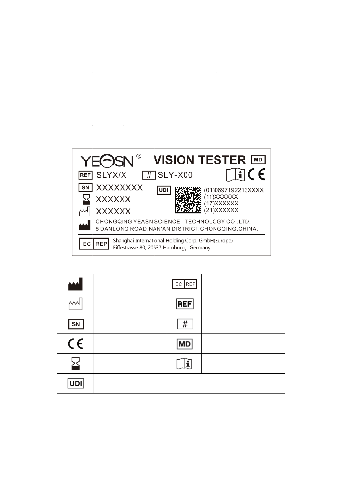
1.4 Nameplate and indications ................................................................................. 2
2. Safety Notice ................................................................................................................ 4
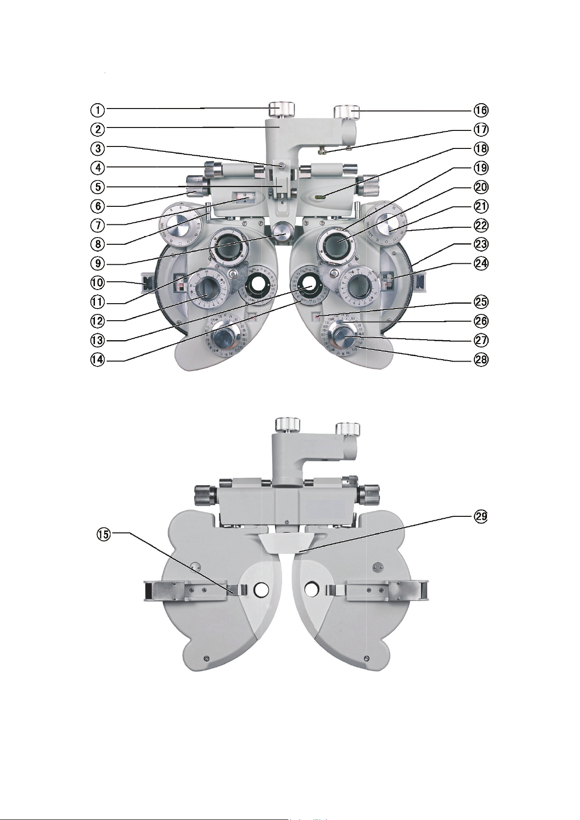
3. Configuration................................................................................................................ 5
4. Assembly ...................................................................................................................... 9
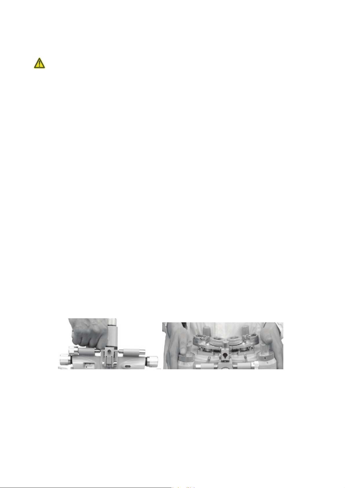
4.1 Attaching Instrument to Ophthalmic Stand........................................................ 9
4.2 Attaching Near Point Rod, Near Point Card and Card Holder......................... 10
4.3 Attaching face shield ........................................................................................ 10
5. Preventive inspection.................................................................................................. 10
6. Operation Procedures ................................................................................................. 11
6.1 Spherical Lens .................................................................................................. 11
6.2 Cylinder Lens ................................................................................................... 11
6.3 Auxiliary Lens .................................................................................................. 12
6.4 Cross Cylindrical Lens ..................................................................................... 13
6.5 Rotary Prism..................................................................................................... 14
6.6 Corneal Aligning Device.................................................................................. 15
6.7 Near Point Card ................................................................................................ 19
6.8 Examination Procedures................................................................................... 19
7. Maintenance ............................................................................................................... 32
7.1 Daily Care......................................................................................................... 32
7.2 Checking and Servicing Procedure................................................................... 32
8. Before Requesting Service-Troubleshooting Guide................................................... 32
9. Cleaning & Protection ................................................................................................ 33
10. Environmental Conditions and Service Life ............................................................ 33
10.1 Environmental conditions for normal operation............................................. 33
10.2 Environmental conditions for transportation and storage............................... 33
10.3 Service life...................................................................................................... 33
11. Environmental Protection......................................................................................... 34
12. The responsibility of the manufacturer..................................................................... 34
13. Optional Accessories - Cylinder Lens...................................................................... 34

1
1. Introduction
1.1 Uses
This instrument is applicable with stand and projection for precision measurement of visual functions
such as myopia, hyperopia, astigmatism, visual acuity balance, phoria, stereoscopic vision and visual
acuity amalgamation.
Contraindications: none
Target groups of patients: adults, children
Intended users: optometrists in hospital ophthalmology and optical shops
Specific qualifications of device users and/or other persons: have a qualification certificate for
optometry and glasses.
1.2 Characteristics
⌂Unique design of butterfly-shape appearance.
⌂Capable of checking up all-sided visual functions, accurate and comfortable in measurement.
⌂Exquisite manufacturing technique, with comfortable feel.
⌂High quality plated-film used in all optic lenses.
⌂Technology and design patents
1.3 Main technical indexes
1.3.1 Spherical Lens Range of measurement:-19.00D~+16.75D
Step length:0.25D (being 0.12D when 0.12D auxiliary lens is used)
1.3.2 Cylindrical Lens Range of measurement:0~-6.00D
(being 0~-8.00D when additional lens is used)
Step:0.25D (being 0.12D when additional lens is used)
1.3.3 Axis of Cylindrical Lens Range of measurement:0~180°, Step:5°
1.3.4 Cross Cylindrical Lens ±0.25D
1.3.5 Rotary Prism Range of measurement:0~△
20
Step:△
1
1.3.6 Prism basal angle Range of measurement: ~
0 180°, :
Step 5°
1.3.7 Pupil Distance Range:50mm~75mm
Step:1mm
1.3.8 Aggregated Adjustment ∞,380mm

1.3.9 Adj
u
1.3.10 ver
t
1.3.11 Ov
e
1.3.12 We
i
1.4 Name
p
Name plat
e
In case th
e
contact au
t
Key to sy
m
u
stment of
F
t
ex Distanc
e
e
rall Dime
n
i
ght
p
late and i
n
e
and indic
a
e
name pl
a
t
horized di
s
m
bols of th
e
F
orehead R
e
e
n
sions
n
dications
a
tions are s
t
a
te is not s
t
s
tributors.
e
name plat
e
Manufac
t
Date of
m
Serial nu
m
CE mark
i
Expiratio
Unique
D
e
st 16
m
13.
7
33
5
4.5
k
t
icked on t
h
t
icked well
e
sticked o
n
t
ure
r
m
anufacture
m
be
r
i
ng
n date
D
evice Iden
t
2
m
m
7
5mm
5
mm (Leng
t
k
g
h
e instrume
n
or the cha
r
n
the instru
m
t
ifie
r
t
h)×310m
m
n
t to arise e
n
r
acters bec
o
m
ent:
Aut
h
rep
r
Cat
a
Mo
d
Me
d
Co
n
m
(Width)×9
0
nd
-users' n
o
o
me uncle
a
h
orized Eu
r
r
esentative
a
logue nu
m
d
el numbe
r
d
ical devic
e
n
sult instruc
0
mm(Heig
h
o
tice.
a
r to recog
n
r
opean
m
be
r
e
tions for u
s
h
t)
n
ize, pleas
e
e
e

Name plat
e
Key to sy
m
e
sticked o
n
m
bols of th
e
G.W.
n
the packa
g
e
name plat
e
Gross W
e
Humidit
y
identific
a
Country
o
Fragile,
h
care
Keep dry
g
ing:
e
sticked o
n
e
ight
y
range
a
tion
o
f manufac
t
h
andle with
3
n
the packa
g
DI
M
t
ure
g
ing:
M
.Di
m
At
m
ide
n
Te
m
Thi
s
Sta
c
m
ension
m
ospheric p
r
n
tification
m
perature li
m
s
way up
c
king limit
b
r
essure ran
g
m
it
b
y 5
g
e

4
2. Safety Notice
Please read the following precautions carefully to avoid personal injury, device damages or
other possible hazards:
●Use the device indoors and keep it clean and dry; do not use it under inflammable, explosive, high
temperature and dusty environment.
●Do not use the device near water; also be careful not to make any kinds of liquid drop onto the
device. Do not place the device in damp or dusty places, nor place it where humidity and
temperature change quickly.
●Ensure that the equipment is installed firmly and reliably before use; if the equipment falls, it may
cause personal injury or equipment failure.
●Do not set the instrument with face down or exert pressure onto surface of lens, and do not touch
lens by hand.
●The instrument shall not be put in a damp and dusty room.
●All moving parts can be turned in dual-direction. However, care must be taken to do it, and do not
turn it beyond the limit position so as to avoid damage to the device.
●The plastic part (Forehead Rest and spirit level, etc.) that can be scrubbed shall be swabbed down
using cotton cloth, and do not use cleaning liquid or other chemicals.
●Vision tester belongs to precision instrument, so do not dismantle it at random.
●When taking the vision tester, one should hold mounting handle (Fig.1) at upper part of the
instrument or carry left and right ends of the instrument by both hands (Fig.2).
Fig.1 Fig.2
●Notification:Any serious event related to the device to the user and/or patient shall be reported to
the manufacturer and competent authority of the Member State where the user and/or patient is
located.

3. Con
fi
fi
guration
5
Fig.3
Fig.4

6
○
1 Rotation Adjustment Knob
Used to adjust direction of instrument’s main body
○
2 Mounting Handle
Used to install the instrument onto eye-optometry table
○
3 Clamping Screw
Used to fix near-point rod
○
4 Leveling Adjusting Knob
Used to adjust level position of the instrument
○
5 Near Point Rod Holder
Used to attach near-point testing mark rod to hanger frame
○
6 Pupil Distance Knob
Used to adjust pupil distance
○
7Pupil Distance Scale
Used to display pupil distance
○
8 Vergence Lever
Used to adjust corner of device’s left and right disks
○
9 Forehead Rest Knob
Used to adjust patient’s forehead position
○
10 Corneal Aligning Aperture
Used to display position of patient’s cornea vertex
○
11 Prism Rotation Knob
Used to adjust prism power
○
12 Rotary Prism
Used to test phoria or binocular balance
○
13 Examination Aperture

7
Aperture for test, with various lenses set here.
○
14 Cylindrical Lens Axis Scale
Used to indicate cylindrical lens axis angle
○
15 Face shield chip
Fix face shield
○
16 Fixing Hand-wheel
Used to fix instrument to ophthalmic stand
○
17 Tightening Screw
Used to fix instrument to ophthalmic stand, and stored in accessory box
○
18 Spirit Level
Used to indicate level direction
○
19 Rotation Knob
Used to adjust astigmatic axis of cross cylindrical lens
○
20 Cross Cylindrical Lens
Used to precisely check astigmatic power and axis
○
21 Auxiliary Lens Knob
Used for various visual acuity tests
○
22 Strong Spherical Power Knob
Used to adjust big spherical lens power, step:3.00D
○
23 Weak Spherical Power Dial
Used to adjust small spherical lens power, step:0.25D
○
24 Spherical Power Scale
Used to display spherical lens power
○
25 Cylindrical Power Scale
Used to display cylindrical lens power

8
○
26 Cylindrical Lens Axis Knob
Used to adjust cylindrical lens axis
○
27 Cylindrical Lens Knob
Used to set cylindrical lens to examination aperture
○
28 Cylindrical Lens Axis Scale
Used to display angle of cylindrical lens axis
○
29 Forehead Rest
Patient’s forehead rests here.
○
30 Instruction Manual
○
31 Near Point Rod
Card holder is attached to position of near point measuring on this rod.
○
32 Near Point Card
Including near point sight mark
○
33 Dust Cover
Use dust cover to cover instrument when it is not in use to protect it from dust.
○
34 Accessories Box
Used to store the standard accessories
○
35 Face shield
Left and right face shield s, one each, are installed on position where instrument and
patient’s nose contact.
○
36 Balloon with Brush
Used to clean lens
○
37 Additional Lens (Optional)
Used to change testing range and precision
○
38 Internal Screw Angle Wrench

9
Used to install the near point rods
Screws
Used to connect two near points rods
Fig.5 Fig.6
4. Assembly
4.1 Attaching Instrument to Ophthalmic Stand
a.When assembly is conducted, first insert the mounting rod extending from the ophthalmic stand to
hole of mounting handle ○
2, and fix it with fixing hand-wheel ○
16 . Then tighten tightening screw
○
17 under mounting handle ○
2. Tightening screw ○
17 is stored in standard accessories box ○
34 .
b.Turn leveling adjusting knob ○
4until air bubble is located at middle position of spirit-level
bubble ○
18 . Loosen rotation adjustment knob ○
1to turn the instrument to the required direction.
Adjust the device to the right position, then fix the hand-wheel ○
1again.
Fig.7

10
*Notice
Fastening screw (placed in accessories box) can be used to better fasten vision tester when it is
not matching with the vision tester holding arm.
4.2 Attaching Near Point Rod, Near Point Card and Card Holder
First, align the connection engravings of the two near point rods, then use ○
38 internal screw angle
wrench to fix the two screws into○
31 . Secondly, put the near point card○
32 into○
31 and tighten the
top screws of the near point rods(Fig.8). Thirdly, install the ○
31 onto the ○
5, tighten the ○
3.
When ○
31 is out of use, lift it up(Fig.9).
Fig.8 Fig.9
4.3 Attaching face shield
Attach face shield ○
35 so that face shield clip ○
15 catches it. Then align face shield aperture with
examination aperture ○
13 (Fig.10).
Fig.10
5. Preventive inspection
The equipment management should carry out preventive inspections before use.
The detection window should be clean.
The device is in a horizontal position.

The lense
s
aligned an
d
Inspection
6. Ope
r
6.1 Spher
i
To show t
h
then turn
c
weak sph
e
from -19.
0
To obtain
increases
o
Note: Alt
h
meaning.
F
b
e read as
6.2 C
y
lin
d
By turnin
g
○
25 , with
(Fig.13).
B
cylinder le
s
and acces
s
d
centered.
cycle: bef
o
r
ation P
r
i
cal Lens
h
e spheric
a
c
ylindrical
l
e
rical powe
r
0
0D~+16.7
5
required
d
o
r decrease
s
h
ough seve
r
F
or exampl
e
'11.50D'.
d
er Lens
g
cylindric
a
range fro
m
B
y turning
ns axis sca
l
s
ories are fi
x
o
re use ever
y
r
ocedur
e
a
l power on
l
ens knob
○
2
r
dial ○
23 ,
5
D, increasi
d
iopter sett
i
s
progressi
v
r
al figures
e
, if '075' is
Fig.1
a
l lens kno
b
m
0.00D to
cylinder l
e
l
e ○
28 , wit
h
x
ed in fron
t
y
day.
e
s
ly (shorten
e
○
2
7 until "
0
value S is
ng or decre
i
ng quickl
y
v
ely in 3.00
D
will appea
r
shown, it s
h
1
b
○
27 , the
6.00D, an
e
ns axis k
n
h
range of
0
11
t
of the det
e
e
d as "S"),
0
0" is sho
w
displayed
asing prog
r
y
, use stro
n
D
diopter s
t
r
on the s
c
h
ould be re
a
F
cylindrical
d increase
s
n
ob ○
26 , t
h
0
~180°; ste
p
e
ction win
d
turn auxili
a
w
n on cylin
d
in spheric
a
r
essively in
n
g spherica
l
t
eps (Fig.1
2
c
ale, only
t
a
d as '0.75
D
F
ig.12
power is s
s
or decrea
s
h
e axis an
g
p
: 5°(Fig.1
4
d
ow, and th
e
a
ry lens kn
o
d
rical powe
r
a
l power s
c
0.25D (Fig
l
power k
n
2
).
t
hree or fo
u
D
', and if '1
1
hown on c
y
s
es progre
s
g
le of cyli
n
4
)
e
instrume
n
o
b ○
21 to
r
scale ○
25
c
ale ○
24 ,
w
.11).
n
ob ○
22 , th
u
r digit nu
m
1
50' is sho
w
y
lindrical
p
s
sively in
0
n
der lens i
s
n
t should b
e
O position
,
. Then tur
n
w
ithin rang
e
en value
S
m
bers hav
e
w
n, it shoul
d
p
ower scal
e
0
.25D step
s
s
shown o
n
e
,
n
e
S
e
d
e
s
n

6.3 Auxili
a
Turn auxi
l
Correspon
d
The meani
OA
BL
±.50
6∆U
PH
+.12
RF
MRRH
MRRV
a
r
y
Lens
l
iary lens
k
d
ing refere
n
ng of each
m
Open ap
e
Occlude
r
Cross c
y
6 diopte
r
A 1mm
d
(due to
r
+0.12D
s
Cross pie
c
Red Filt
e
MR:
M
MR:
M
Fig.
1
k
nob ○
21 ,
n
ced lens
w
F
m
ark.
e
rture
r
: to block
t
y
linder lens,
r
base up p
r
d
iameter pi
n
r
efractive a
b
s
pherical le
n
c
e
er
M
addox rod
s
M
addox rod
s
1
3
the requir
e
w
ill appear i
n
F
ig.15
t
he light pa
t
with horiz
o
r
ism, used
fo
n
hole is pr
o
b
normity o
r
n
s, and sph
e
s
,RH:R
e
s
,RV:R
e
12
e
d symbol
n
the exam
i
t
h
o
ntal plus
+
fo
r horizont
a
o
vided, use
d
r
their reas
o
e
rical pow
e
ed
,Horizo
n
ed
,Vertic
a
is to be
s
i
nation ape
r
Fig.
+
axis. Used
a
l phoria te
s
d
to determ
i
o
ns)
e
r can be se
t
n
tal
a
l
Fig.14
s
et at 12
o
r
ture ○
13 (
F
16
for presby
o
s
t
i
ne reason
o
t
by 0.12D
o
'clock pos
i
F
ig.15 and
o
pia test
o
f poor visi
o
i
tion. The
n
Fig.16).
o
n
n

PF
RL
10∆I
GF
MRWH
MRWV
To chang
e
rear cove
r
properly i
n
lens knob
Removing
reposition
6.4 Cross
It is used
f
front of e
x
hand-whe
e
cylindrica
l
Polaroid
stereosco
Retinos
c
10 diopte
r
Green c
o
MR:M
a
MR:
M
e
direction
o
r
glass usi
n
n
dexed and
○
21 in b
these two
of lens is p
o
C
y
lindric
a
f
or precise
x
amination
e
l
d
irection
l
lens. Whe
n
filter, used
pic visio
n
c
opic lens;
+
r
b
ase in pr
o
lo
r
-filter l
e
a
ddox rods
,
M
addox rods
o
f cross cy
l
n
g screwdr
i
in alignme
n
oth directi
o
screws, au
x
o
ssible to e
n
a
l Lens
determinat
aperture.
T
stands fo
r
n
white dot
for polarizi
n
+
1.50D sph
e
ism, used f
o
e
ns
,
WH:W
h
,WV:
W
l
inder lens
i
ver. Rotat
e
n
t with exa
m
o
ns, a scre
w
x
iliary len
s
n
sure it is
p
ion of cyli
n
T
he lette
r
“P
”
r
axis. Wh
e
aligns wit
h
13
n
g testing
o
e
rical lens
(
o
r vertical
p
h
ite,Hori
z
W
hite,Vert
i
and polar
o
e
the auxil
i
m
ination a
p
w
and was
h
s
can be th
e
p
laced in a
p
Fig.17
n
der power
”
at its fro
n
e
n red dot
h
“P”it indi
c
o
f stereosco
p
(
67cm)
p
horia test
z
ontal
i
cal
o
id filter, fi
r
i
ary lens k
n
p
erture ○
13
h
er can be
e
n remove
d
p
roper posi
t
and axis.
T
n
t sustenan
c
aligns wit
h
c
ates plus +
0
p
ic visiona
n
r
st remove
n
ob ○
21 u
n
. By slight
l
seen abov
e
d
. By rever
t
ion (Fig.17
)
T
urn cross
c
e face sta
n
h
“P” it i
n
0
.25D cyli
n
nd
b
inocula
r
the retaini
n
n
til auxilia
r
l
y turning t
h
e
and belo
w
sing above
)
.
cylindrical
n
ds for the
n
dicates mi
n
n
drical lens.
r
balance o
f
n
g ring an
d
r
y lens i
s
h
e auxiliar
y
w
the lens
.
procedure
,
lens to th
e
power, an
d
n
us -0.25
D
f
d
s
y
.
,
e
d
D

14
Fig.18 Fig.19
Fig.20
6.5 Rotary Prism
Turn rotary prism ○
12 by holding its base to set it on the examination aperture. Turn prism rotation
knob ○
11 until the required prism power is set. What the black triangle arrow indicates is the
current prism power. For example, prism power indicated in Fig.22 is 0, that in Fig.23 means base
in 3∆prism power, and that in Fig.24 means base up 3∆prism power.
The purpose of below markings:
:Indicate the prism base direction.
When and 0 are in the horizontal position, the prism base is labeled as vertical direction.
When and 0 are in the vertical position, the prism base is labeled as horizontal direction.
::Current prism base value indicates.
Fig.21 Fig.22

6.6 Corne
a
Turn fore
h
forehead c
l
20cm aw
a
pointer ac
m
line in th
e
wearing di
If apex of
power sho
u
cornea (st
a
actual spe
c
b
e made a
c
a
l Ali
g
nin
g
h
ead rest
k
l
osely on f
o
a
y. Look a
t
m
e of corn
e
e
aperture
m
stance. Thr
the corne
a
u
ld be the
v
a
ndard val
u
c
tacle wear
i
c
cording to
F
i
g
Device
k
nob ○
9
t
o
rehead res
t
t
the apex
e
al alignin
g
m
eans the
m
ee shorter l
i
a
of testee
i
v
alue meas
u
u
e 13.75m
m
i
ng distanc
e
Table 1 an
d
i
g.23
t
o adjust
p
t
○
29 , look
of the pat
i
g
aperture
○
m
easuring
i
nes are pr
o
i
s positione
u
red when
m
+ correcti
o
e
is differe
n
d
Table 2.
15
p
osition of
through th
e
i
ent's corn
e
○
10 aligns
w
distance is
o
vided by 2
m
d on secon
spectacle i
s
o
n value o
f
n
t from the
s
Fig.2
4
forehead
e
corneal al
i
e
a (Fig.25)
w
ith the lo
n
13.75mm,
m
m equal
d
d shorter l
i
s
placed at
f
second sh
o
s
tandard v
a
4
rest ○
29 .
A
i
gning ape
r
after the
e
n
ger line o
n
which is
t
d
istance aw
a
i
ne from th
17.75mm
a
o
rter li
n
e 4
m
a
lue (13.75
m
A
fter setti
n
r
ture ○
10
fr
e
xaminatio
n
n
the scale.
t
he standar
a
y from the
e longer li
n
a
way from
m
m =17.75
m
m
m), corre
c
n
g patient'
s
fr
om aroun
d
n
aperture'
s
The longe
r
d
spectacl
e
longer lin
e
n
e, the len
s
apex of th
e
m
m). If th
e
c
tion shoul
d
s
d
s
r
e
e
.
s
e
e
d

16
Example 1 Assume that data of S +8.00D is obtained when the apex of the cornea positioned at the
second shortest line from the longest line, meaning that it is 4mm away from the standard wearing
distance. When referring to the correction factor in Table 1, it is known that the applied correction
factor is +0.26D for +8.00D diopter and 4mm distance. Therefore, the actual diopter of a patient
who wears 13.75 distance standard spectacle is (+8.00D) + (+0.26D)=8.26D. The correction value
changes by 0.25 D or 0.12D.
Example 2 Assume that the apex of cornea is between the second and third shortest lines from the
longest line (5mm from the standard line), the obtained data is S-11.50D. It is known when
referring the correction factor in Table 2 that for -11.50D and 5mm distance, the correction value
should be (0.57+0.68)/2= 0.62D.Thus the actual diopter of a patient who wears 13.75 distance
standard spectacle is (-11.50) + (+0.62)= -10.88D.
Example 3 When the cornea apex is on the third shortest line from the longest one, the obtained
value is -14.00D: It is known when referring to correction factor in table 2 that for -14.00D and
6mm distance, the correction value should be 1.08D. So the actual diopter of a patient who wears
13.75 distance standard spectacle is (-14.00)+(1.08)= -12.92D.
If more accurate measurement is required, please calculate it according to following formula.
D'=D±
2
1000
LD
LD−
D:Measured power
D':Corrected power
L:Difference between measured distance and wearing distance(mm)
Table of contents