ADCMT 12701A User manual

©2009 ADC CORPORATION First printing February 28, 2009
All rights reserved. Printed in Japan
12701A
Test Fixture
OPERATION MANUAL
Manual Number FOE-00000045A00


12701ATest Fixture Operation Manual
Precautions for Handling 12701A
To operate the 12701A correctly and safety, please observe the following instructions. Note that ADC Cor-
poration bears absolutely no responsibility for the result of operations caused due to incorrect or inappro-
priate use of this instrument.
Please observe the following instructions to prevent danger such as electric shock:
(1) Always use the safety mechanism of the 12701A that allows and stops voltage application by opening
and closing the cover. (Connect the LID SIGNAL of the 12701A and the INTERLOCK or LID SIG-
NAL of the measuring instrument using a cable.
(2) Ground the 12701Abefore use.
(3) Do not touch the test box while voltage is being applied.
When the HI OUTPUT of the 6245, 6246 (Bch), 6242 or 6244 and the FORCE/SENSE 1 to 8 on the
rear panel of the 12701A are connected, and the relay terminal DG 1 to 8 and the TEST BOX GUARD
are connected, the test box and DG will become the same potential, and the maximum voltage of the
HI OUTPUT may occur on the test box.
(4) When placing or removing DUT, check chat no voltage applied to the 12701A.
(5) Close the cover during measurement to perform accurate measurement.
The cover has a shielded, light-shielded and safety structure.
(6) Watch out for vibration to perform accurate measurement.
The vibration of a cable or fixture during low current (1 pA or lower) measurement may cause varia-
tion in measured values.
(7) Check that the voltage or current applied to the 12701A is within the maximum input voltage or cur-
rent range.
Note that the operating temperature range varies depending on the maximum input current.
(8) Use the test box A04509with the average current value for a second of 1 A or less. The maximum in-
put current value for DC is 1 A. For pulse, the average current value for a second that is obtained by
the following formula should be 1A or less.
Average current = Input current value (up to 20 A peak) × Pulse width / Pulse cycle
e.g. When the input current value is 20 A and the pulse cycle is 1 s, the pulse width should be 50 ms
or less. When the input current value is 20 A and the pulse cycle is 10 ms, the pulse width should
be 0.5 ms or less.
(9) When connecting a measuring instrument with the 12701A
zFor how to handle the measuring instrument, refer to its operation manuals.
zGround the measuring instrument before use.
zWhen using the R8340 or 8340A as measuring instrument, short-circuit the LO and the GND.


Preface*
12701ATest Fixture Operation Manual
Preface
This manual describes the functions of the 12701A test fixture, how to set up and how to measure.
zManual Configuration
This manual consists of the following chapters:
1. Introduction
(1) Product Overview
(2) Supplied Accessories and Optional Accessories
(3) Environmental Conditions
(4) Cleaning, Storage and Transportation of the
Product
Be sure to read through this chapter
before use.
2. Panel Description
(1) Relay Terminals
(2) Rear Panel
Describes the name and function of
each part on the panel.
3. Measurement Examples
(1) Resistance Measurement
(2) Current Measurement
Describes how to use the 12701A.
4. Functional Description
(1) Driving Guard Function
(2) Internal Connection
Describes the driving guard function
and the internal connection.
5. Specifications Describes the specifications.
Appendix 1. Test Box (Socket) Describes the sockets to be mounted on
the 12701A.


C-1*
12701ATest Fixture Operation Manual
Table of Contents
1. Introduction.............................................................................................................................1-1
1.1 Product Overview.........................................................................................................................1-1
1.2 Supplied Accessories....................................................................................................................1-2
1.3 Optional Accessories ....................................................................................................................1-3
1.4 Environmental Conditions............................................................................................................1-5
1.5 Cleaning, Storage and Transportation of the Product...................................................................1-6
1.5.1. Cleaning................................................................................................................................1-6
1.5.2. Storage ..................................................................................................................................1-6
1.5.3. Transportation.......................................................................................................................1-6
2. Panel Descriptions................................................................................................................2-1
2.1 Relay Terminals............................................................................................................................2-1
2.2 Rear Panel.....................................................................................................................................2-3
3. Measurement Examples.....................................................................................................3-1
3.1 High Resistance Measurement .....................................................................................................3-1
3.2 Resistance Measurement ..............................................................................................................3-6
3.3 Diode Leak Current Measurement..............................................................................................3-12
3.4 Diode Leak Current Measurement..............................................................................................3-17
4. Functional Description.......................................................................................................4-1
4.1 Driving Guard Function................................................................................................................4-1
4.2 Internal Connection ......................................................................................................................4-3
5. Specifications.........................................................................................................................5-1
5.1 Electrical Specifications ...............................................................................................................5-1
5.2 General Specifications..................................................................................................................5-2
Appendix.........................................................................................................................................A-1
A.1 Test Box (Socket)..................................................................................................................................................A-1


F-1*
12701ATest Fixture Operation Manual
List of Illustrations
No. Title Page
2-1 Relay Terminals …………………………………………………………... 2-1
2-2 Rear Panel …………………………………………………...……………. 2-3
3-1 Connecting the 12701A with the 8340A …………………………………. 3-2
3-2 Installing the Test Box…………………………………………………….. 3-3
3-3 Connecting the Relay Terminals with the Test Box ……………………… 3-4
3-4 12701A and 8340A Connection Diagram ………………………………… 3-5
3-5 Connecting the 12701A with the 6245 …………………………………… 3-7
3-6 Connecting the Relay Terminals with the Test Box ……………………… 3-9
3-7 12701A and 6245 Connection Diagram (4-wire Connection) ……………. 3-10
3-8 Connecting the 12701A with the 6245 …………………………………… 3-13
3-9 Connecting the Relay Terminals with the Test Box ……………………… 3-14
3-10 12701A and 6245 Connection Diagram (2-wire Connection) ……………. 3-15
3-11 Connecting the 12701A with the 8252 …………………………………… 3-17
3-12 Connecting the Relay Terminals and the Test Box ……………………….. 3-19
3-13 12701A and 8252 Connection Diagram ………………………………….. 3-20
4-1 Driving Guard Function …………………………………………………... 4-1
4-2 Block Diagram ……………………………………………………………. 4-3


T-1*
12701ATest Fixture Operation Manual
List of Tables
No. Title Page
1-1 Supplied Accessories ………………………………………………………. 2-1


1-1
12701ATest Fixture Operation Manual
1.1 Product Overview
1. Introduction
This chapter describes the following items:
(1) Product overview
(2) Supplied accessories and optional accessories
(3) Environmental conditions
(4) Cleaning, storage and transportation of the product
1.1 Product Overview
The 12701A is a test head section which connects to a measuring instrument such as an
electrometer (8240/8340A/8252) or DC voltage/current source monitor (6243/6245/6246) to
perform DC characteristics tests of semiconductors and other electronic components.
It allows easy connection of DUTs to a measuring instrument and offers stable measurement
using shield effect, isolation and light shield.
The following features are included:
zDouble guard shielded structure
zShielded cables used as internal connection leads
zLow current measurement down to 10-14 A
zHigh current measurement up to 20 A
zOutputs an open/close signal for safety measurement
zSafety design using a safety socket
zA variety of accessories that accommodate different types of DUTs
1-2
12701ATest Fixture Operation Manual
1.2 Supplied Accessories
1.2 SuppliedAccessories
The following table shows the accessories supplied with the 12701A. If there is any damage or
defect, please contact ADC Corporation or your sales representative. Quote the model name of
the accessory when ordering.
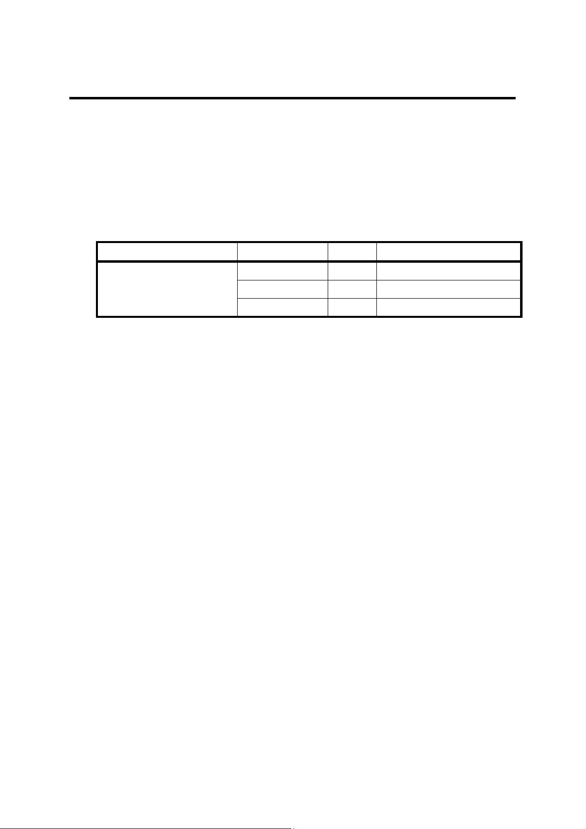
Table 1-1 Supplied Accessories
Name Model Quantity Remarks
Connection lead A01214-20 3 2 dia.-1 dia.
A01215-15 3 2 dia.-2 dia.
A01228-15 3 2x2 dia.-1 dia. coaxial cable

1-3
12701ATest Fixture Operation Manual
1.3 Optional Accessories
1.3 OptionalAccessories
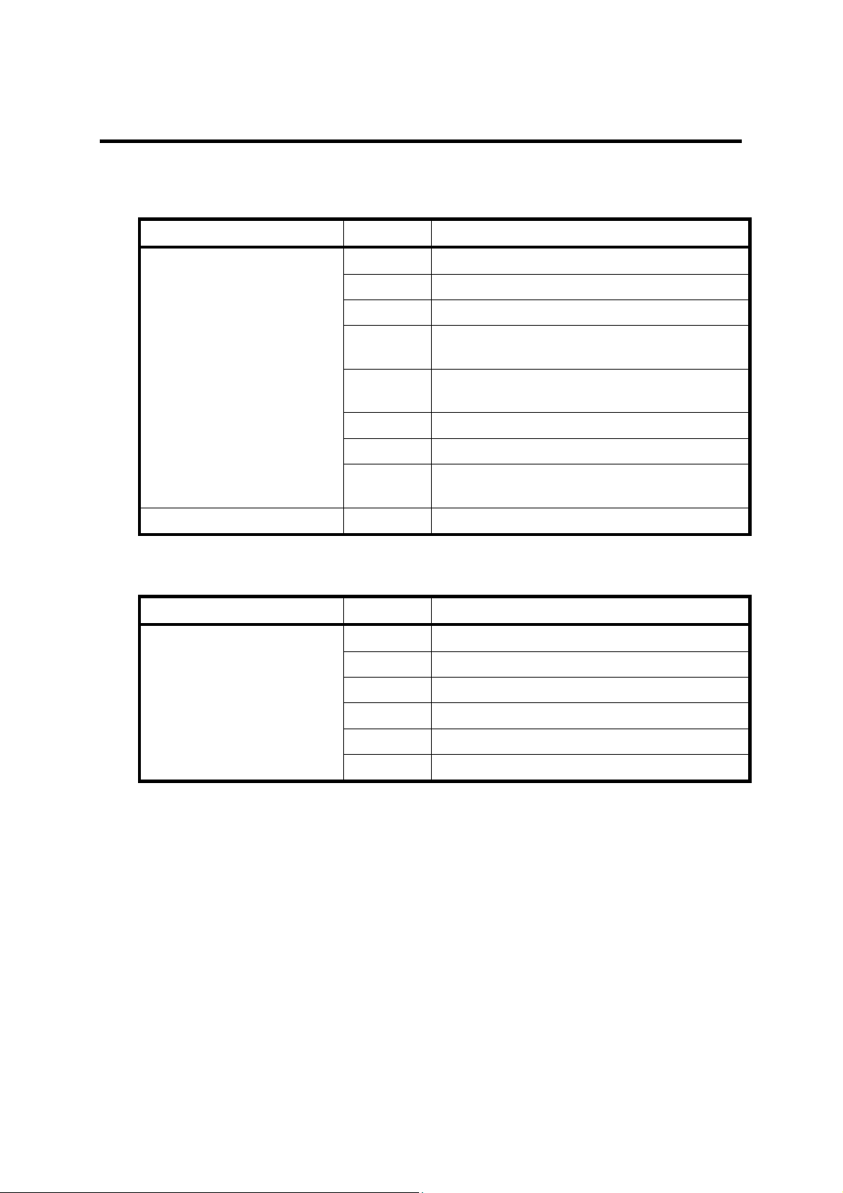
(1) Test boxes
Name Model Remarks
Diode test box A04501 Axial lead-type measurement socket
Applicable to diodes and resistors
Insulating board A04506 Teflon board
Teflon area: 140 x 90 mm
Power transistor test box A04509 TO package 3-pin socket
Applicable to power devices
1-4
12701ATest Fixture Operation Manual
1.3 Optional Accessories
(2) Connection leads and mini hook
Name Model Remarks
Connection lead A01214-20 2 dia.-1 dia. connection lead
A01215-15 2 dia.-2 dia. connection lead
A01216-15 1 dia.-1 dia. connection lead
A01217-25 2 dia.-mini socket connection lead
(with mini hook)
A01218-20 1 dia.-mini socket connection lead
(with mini hook)
A01228-15 2x2 dia.-1 dia. coaxial cable connection lead
A01229-15 2x2 dia.-1x2 dia. coaxial cable connection lead
A01287-15 2 dia.-2 dia. connection lead
(for high current up to 10A)
Mini hook A04701-12
(3) Connection cables to a measuring instrument
Name Model Remarks
Connection cable A01009 TRIAX-TRIAX cable
A01036 BNC-BNC cable
A01239 TRIAX-TRIAX cable for high voltage
A01011 TRIAX-BNC conversion cable
A01038 Banana-banana 4-wire shielded cable
A01240 Banana-banana cable with cover

1-5
12701ATest Fixture Operation Manual
1.4 Environmental Conditions
1.4 Environmental Conditions
Use the 12701A under the following conditions:
zOperating temperature range:
Maximum input current Operating temperature range
0 A to 5 A -20°C to + 75°C
5.1 A to 10 A -20°C to + 70°C
10.1 A to 20 A -20°C to + 65°C
zRelative humidity: 85% or less with no condensation
zAn area free from corrosive gas
zAn area away from direct sunlight
zA dust-free area
zAn area free from vibrations
zA low noise area

1-6
12701ATest Fixture Operation Manual
1.5 Cleaning, Storage and Transportation of the Product
1.5 Cleaning, Storage and Transportation of the Product
1.5.1. Cleaning
Wipe dirt off the 12701A with a soft cloth or small brush as needed. Use the brush when
cleaning around the connectors on the rear panel. When the dirt is hard to remove, use a soft
cloth moistened with a neutral detergent diluted with water.
CAUTION:
1. Do not allow water inside this product
2. Avoid using an organic solvent such as benzene, toluene, xylene or acetone because it
degrades the plastic parts.
3. Avoid using a cleanser.
1.5.2. Storage
Store the 12701A at a temperature ranging from -25°C to + 80°C in an area away from dust
and direct sunlight. When storing it for an extended period (90 days or longer), put the 12701A
in a moisture-proof bag together with desiccants.
1.5.3. Transportation
To transport the 12701A, use the original box that it came in. If the box is not available any
longer, pack it in accordance with the following guidelines.
zPrepare a cardboard box with dimensions that are larger than the external dimensions of
the 12701A by 15 cm or more to allow for cushioning material.
zWrap the 12701A with a protective sheet.
zLine the box with cushioning material to protect all sides of the 12701A.
zClose the box with industrial staples or packing tape.
When sending the 12701A to an ADC CORPORATION sales representative for service or
repairs, attach a label stating the following items.
zCompany name and address
zContact person
zSerial number (on the rear panel)
zType of service required
2-1
12701ATest Fixture Operation Manual
2.1 Relay Terminals
2. Panel Descriptions
This chapter describes the following items.
(1) Relay terminal
(2) Rear panel
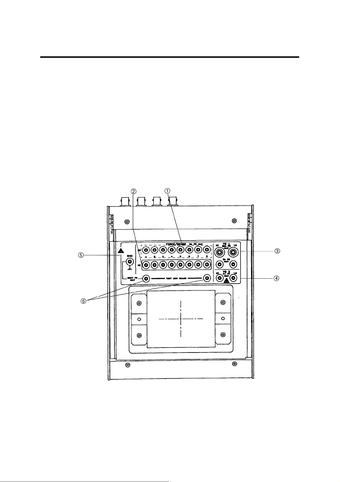
2.1 Relay Terminals
The relay terminals connect to the test box (socket) using the connection leads. The relay
terminals connect with the terminals on the rear panel internally.
Figure 2-1 Relay Terminals

2-2
12701ATest Fixture Operation Manual
2.1 Relay Terminals
1. FORCE/SENSE DG 1 to 8
Connect with the inner shields of the FORCE/SENSE DG 1 to 8 on the rear panel
respectively.
2. FORCE/SENSE HI 1 to 8
Connect with the core wires of the FORCE/SENSE DG 1 to 8 on the rear panel
respectively.
3. VS1 HI and LO
Connect with the VS1 HI and LO on the rear panel respectively. Either 4 dia. or 2 dia.
connection lead can be selected depending on the output current and the test box type.
4. VS2-HI and LO
Connect with the VS2-HI and LO on the rear panel respectively.
5. GND
Connects with the GND on the rear panel. Its potential is equal to those of the outer shields
of the case and the triaxial connectors.
6. TEST BOX GUARD
Connects with the mount of the test box (socket). (See Figure 3-2) Ensure to connect it to
the GND or DG. For how to connect it, refer to Chapter 3, "Measurement Examples."
Applying voltage to the connectors on the rear panel will generate voltage on the
relay terminals equally.
Always disconnect the relay terminals from the test box while applying voltage.
Treat the terminals with great care as follows:
zMaximum 350 V voltage may occur on the FORCE/SENSE DG and HI 1 to 8.
zMaximum 300 V voltage may occur between VS1 HI and LO.
zVS1 HI 4 dia. and 2 dia. are connected. In the same way, VS1 LO 4 dia. and 2
dia. are connected.
zMaximum 1000 V voltage may occur between VS2 HI and LO.
WARNING!
Table of contents
Popular Test Equipment manuals by other brands

Tietzsch
Tietzsch ProfiSafe LSP 4L User instructions

OPTICOM
OPTICOM LCDI-56T - DATASHEET 3 datasheet

Bante Instruments
Bante Instruments PHscan30L instruction manual

SIGLENT
SIGLENT SDS2000X Plus Series quick start

Gardco
Gardco PG-1 user manual

Commercial Electric
Commercial Electric DUALCHECK CE-VD7504GFI Use and care guide


