iv
────────────────────────────────────────────────────
Notes on Use
────────────────────────────────────────────────────
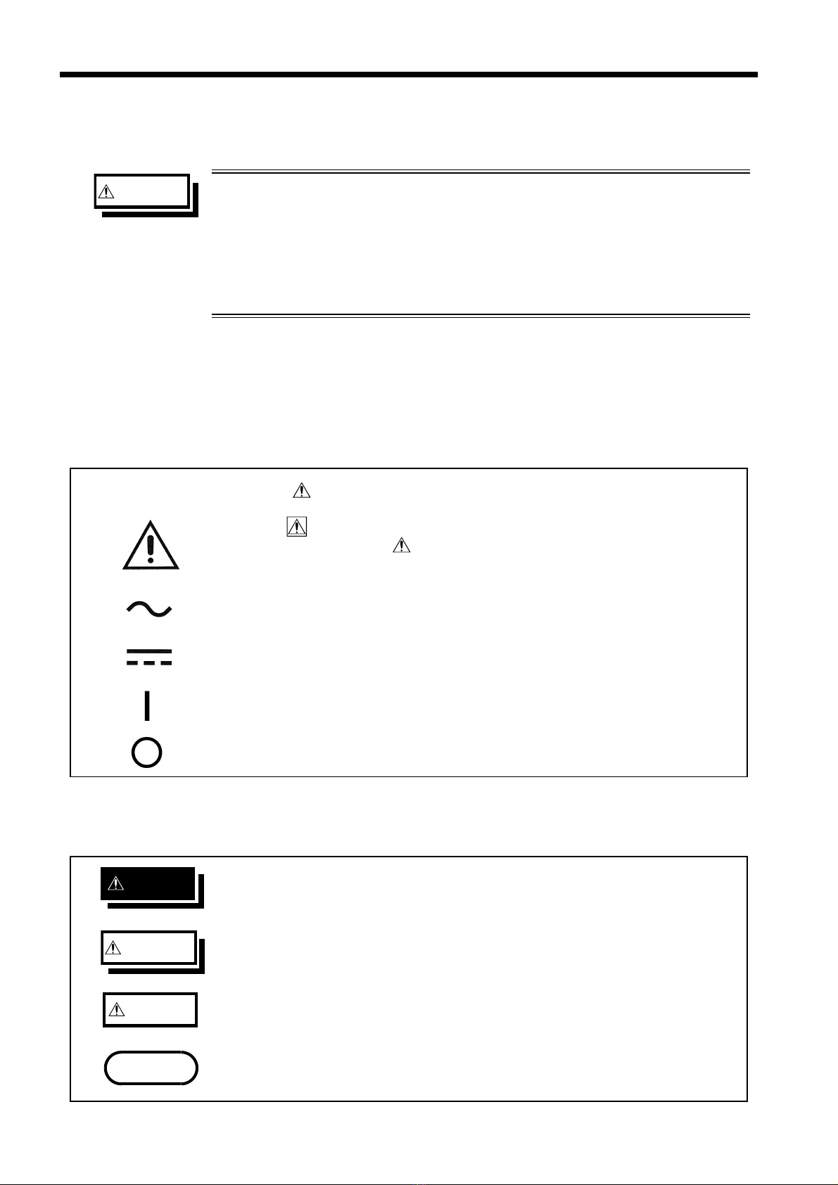
DANGE
Be sure to ensure the floating state for a battery circuit (measured
object) with voltage exceeding 30 Vrms, 42.4 Vpeak, or 60 VDC.
Connecting the instrument to a circuit exceeding 30 Vrms, 42.4
Vpeak, or 60 VDC may lead to electric shock.
WARNIN
Connect SOURCE and SENSE (banana plug) in the proper manner.
For the correct procedure, refer to Section 3.3 "Connecting the
Measurement Leads ".
To avoid injury or damage to the instrument, do not attempt to
measure AC voltage, or DC voltage exceeding 60 V.
Do not allow the instrument to get wet, and do not take
measurements with wet hands. This may cause an electric shock.
Do not use the instrument where it may be exposed to corrosive or
combustible gases. The instrument may be damaged or cause an
explosion.
To avoid electric shock when measuring live lines, wear appropriate
protective gear, such as insulated rubber gloves, boots and a safety
helmet.
CAUTIO
・Do not store or use the instrument where it could be exposed to direct
sunlight, high temperature or humidity, or condensation. Under such
conditions, the instrument may be damaged and insulation may
deteriorate so that it no longer meets specifications.
・This instrument is designed for use indoors. It can be operated at
temperatures between 0 and 40℃without degrading safety.
・Do not input voltage and current between SOURCE-Hi and SENSE-Hi or
between SOURCE-Lo and SENSE-Lo.
・Various connectors are provided on the outer panel of the instrument.
Make sure the instrument is turned off before connecting cables to these
connectors. To prevent short-circuits, make sure connections are made
correctly.
・The GND terminals on the external control terminal, external output
terminal, RS-232C interface, GP-IB interface, and printer interface are
grounded. This means that the devices connected to the GND terminals
are grounded. Take care in handling them.
otes on Use
Follow these precautions to ensure safe operation and to obtain the full
benefits of the various functions.
Preliminary Checks
Before using the instrument the first time, verify that it operates
normally to ensure that the no damage occurred during storage or
shipping. If you find any damage, contact your dealer or Hioki
representative.
Before using the instrument, make sure that the insulation on the
measurement leads is undamaged and that no bare conductors are
improperly exposed. Using the instrument in such conditions could
cause an electric shock, so contact your dealer or Hioki representative
for replacements.