YEC '04 YZF-R1 Manual

’04 YZF-R1
KIT MANUAL
The Performance Edge
for top-ranking riders

2004 YZF-R1 Kit Manual
Please note :
•It should be understood that these kit parts are not covered by warranty.
•The manufacturer does not assume any responsibility for problems caused by
these parts.
•These kit parts are intended for racing alone. They are not to be used in any
circumstances on public roads.
•The specifications and methods of use of these kit parts and the contents of the
present manual are subject to improvement changes without notice.
•This manual is intended for persons with knowledge and experience of
motorcycles. Please refer to the service manual for information on part assembly
and maintenance.

CONTENTS
1 Standard Specifications ...................................................................................1
2 Kit Parts .............................................................................................................2
2-1 Basic Kit Set Contents..............................................................................2
2-2 Engine Parts ..............................................................................................2
1. Maintenance set (5VY-MAINT-70).......................................................2
2. Spark Plugs ........................................................................................3
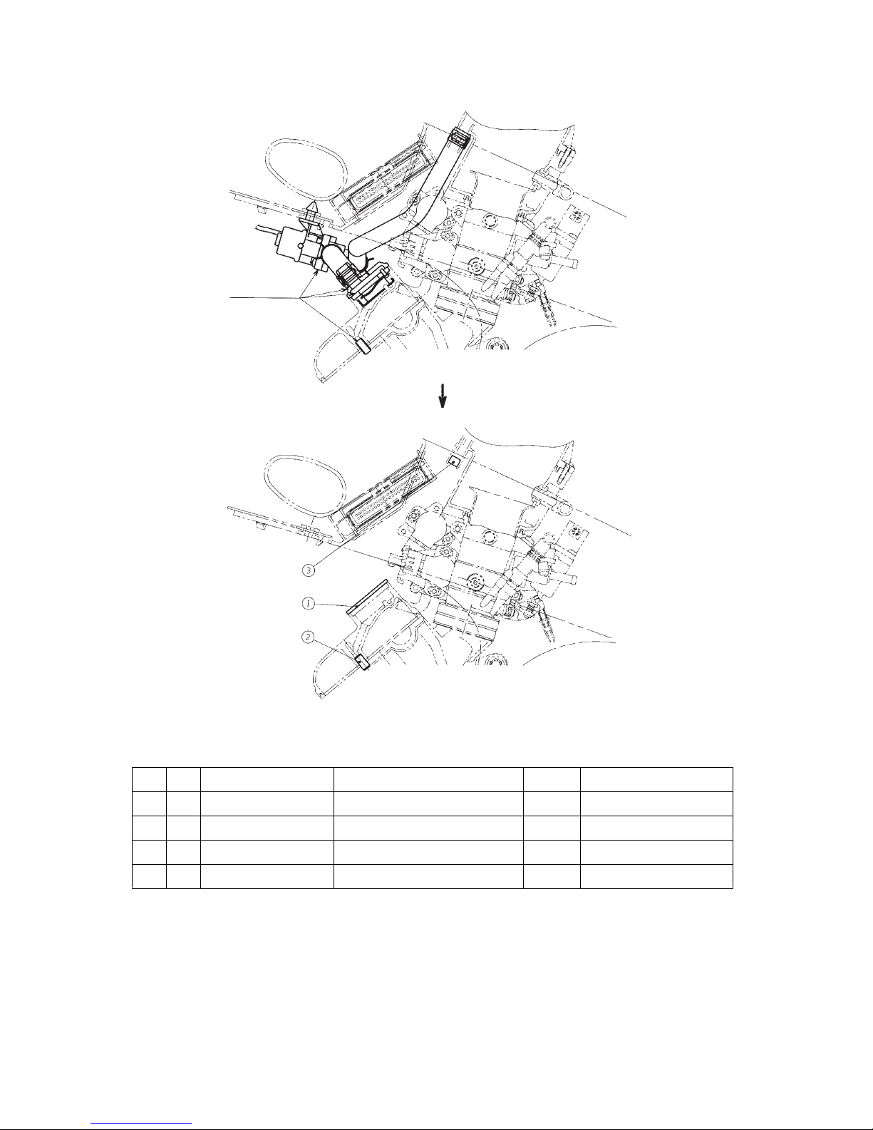
3. AIS Plug Set (5VY-A4890-70) .............................................................3
4. Gaskets...............................................................................................4
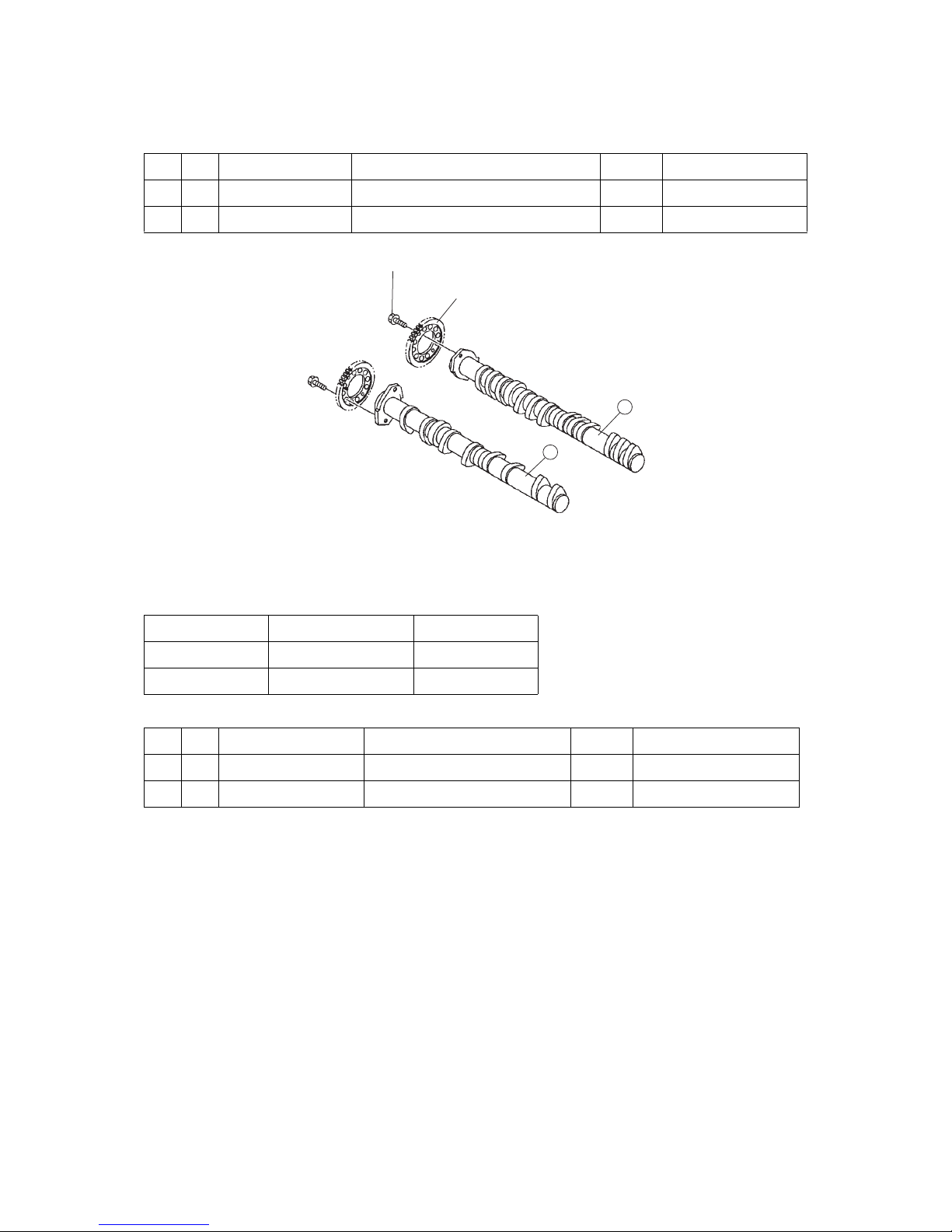
5. High-lift Camshaft, Valve Spring ........................................................5
6. Standard-lift Camshafts ....................................................................6
7. Flat Valve Set (5VY-A2100-70)............................................................7
8. Sub-radiator Set (5VY-A240A-70) ......................................................8
9. Funnel Set (5VY-A4460-70) ...............................................................9
10. Clutch Spring, Clutch Boss .............................................................10
11. ACM Rotor .......................................................................................11
12. Engine Control Unit (ECU) ................................................................12
13. Wire Harness ...................................................................................23
14. Headlight Harness Set (5VY-F4350-70) ...........................................23
2-3 Chassis Parts ..........................................................................................25
15. Oil Catcher Tank Set (5VY-C1707-70) .............................................25
16. Chassis Protector Set (5VY-C117G-70) ...........................................26
17. Rear Suspension Spring...................................................................26
18. Front Fork Spring Set .......................................................................27
19. Front Disk Assembly (5VY-2581T-70) ..............................................28
20. Front Wheel Attachment Set ............................................................29
21. Rear Arm Attachment Set, Rear Wheel Attachment Set .................30
22. Sprocket, Sprocket Nut....................................................................34
23. Throttle Set (5VY-C6300-70).............................................................34
24. Footrest Set (5VY-C7400-70)............................................................36
25. Front Stay Set (5VY-C8350-70) ........................................................38
2-4 Other.........................................................................................................39
26. Valve Seat Cutter Set........................................................................39

3 Installation Precautions ..................................................................................40
3-1 Checking the Valve Seats.......................................................................40
3-2 Selecting the crankshaft bearing...........................................................42
3-3 Selecting the connecting rod bearing...................................................43
3-4 Installing the piston, piston ring and connecting rod ........................45
3-5 Crankcase installation ...........................................................................47
3-6 Cylinder head tightening (calibrated wrench tightening method)......48
3-7 Camshaft installation..............................................................................49
3-8 Cam chain tensioner installation...........................................................50
3-9 Engine mounting.....................................................................................51
3-10 Front axle installation .............................................................................52
Headlight cord wiring diagram .......................................................................56
2004 YZF-R1 Wiring Diagram..........................................................................57

- 1 -
1 Standard Specifications
Item Standard Basic Kit
Displacement
998 cm
3
Bore/stroke
Primary reduction gear ratio
77,0 mm/53,6 mm
65/43 (1.512)
Compression ratio
Surface honing
12.4:1
-
13.3:1
0,45 mm
Squish height
0,75 mm 0,60 mm
Camshaft INT
Nominal
Major axis
5VY-00
292° – 7.6
32,9 mm
5VY-70
286 – 8.5
33,8 mm
Camshaft EXT
Nominal
Major axis
5VY-00
284° – 7.5
30,8 mm
5VY-70
288 – 8.5
31,8 mm
Valve timing (event angle)
INT
EXT
105°
105°
105°
105°
Valve clearance
INT
EXT
0,17 mm – 0,23 mm
0,27 mm – 0,33 mm
Throttle body
MIKUNI
Throttle valve passage diameter 45.0 mm
Exhaust system 4-2-1 type, #1-#2/#3-#4 connected
Transmission
1st
2nd
3rd
4th
5th
6th
Constant mesh 6-speed box
38/15 (2.533)
33/16 (2.063)
37/21 (1.762)
35/23 (1.522)
30/22 (1.364)
33/26 (1.269)
Clutch Wet type, multiple disc
Ignition timing
DC-CDI

- 2 -
2KitParts
2-1 Basic Kit Set Contents
Spark plug set
Head gasket (0.30 mm)
High lift camshaft (INT, EXT)
Valve spring set
Funnel set
AIS plug set
Clutch spring set
ACM rotor
Wire harness set
Engine control unit
Kit manual
Note:
The part marked [ * ] at the top of the parts list is included in the kit, but if it is
specifically needed, it is available from Yamaha authorized dealers.
2-2 Engine Parts
1. Maintenance set (5VY-MAINT-70)
Parts List
No. PART No. PART NAME Q’TY REMARKS
* 1 5VY-11181-00
GSKT., H/C
3
* 2 5VY-11351-00
GSKT, 1
3
* 3 5VY-11603-00
RING SET
12
* 4 5VY-1165A-01
BOLT, CON-ROD
12
* 5 90468-12069
CIRCLIP
12
* 6 4TV-12119-00
SEAL, STEM
36
INT
* 7 4SV-12119-00
SEAL, STEM
24
EXT
* 8 5VY-13414-00
GSKT, STRAINER
3
* 9 5VY-15451-00
GSKT COVER1
3
ACM
* 10 5VY-15461-00
GSKT COVER2
3
CLUTCH
* 11 5VY-15456-00
GSKT 1
3
PICK UP
* 12 5VY-15462-00
GSKT COVER3
3
BREATHER
* 13 90179-20007
NUT
3
CLUTCH BOSS
* 14 90215-30233
WASHER LOCK
3
SPROCKET
* 15 93102-40330
OIL SEAL
3
DRIVE AXLE
* 16 90110-06027
BOLT
9
MAIN AXLE

- 3 -
2. Spark Plugs
Parts List
Set No. : 5FL-R045Q-70 (R0045Q-10, 4 plugs)
CAUTION :
Since these spark plugs have a copper gasket, caution is needed during
installation on the following points.
1. The tightening torque is 1.0 – 1.2 kg·m.
2. When not checking the torque, tighten by rotating through only 30° after
manual tightening in the case of new plugs. When reusing plugs, tighten by
rotating through 15°.
3.
AIS Plug Set (5VY-A4890-70)
This plug set is used when the AIS (Air Induction System), an exhaust gas purifying
system, is removed.
Parts List
Installation
1. Remove the hose attached to the cylinder head cover and the air cut-off valve
accompanying the hose.
2. Remove the cap fitted to the hose, remove the reed valve and plate from inside.
3. Install the plate (5SL-1482L-70) in replacement of the cap. Apply liquid gasket to
the plate.
4. Remove the cylinder head cover and the four collars fitted to the cover. Install the
PIN (93608-16M16).
5. After removing the hose connected to the air filter casing form the air cut-off
assembly, insert the PLUG (90336-10020) onto the side of the air filter casing to
close the opening.
No. PART No. PART NAME Q’TY REMARKS
15
FL-94700-70 PLUG, SPARK 1 NGK R0045Q-10
No. PART No. PART NAME Q’TY REMARKS
1 5SL-1482L-70 PLATE 2
* 2 93608-16M16 PIN 4
* 3 93306-10020 PLUG 1
Reused (15°)
New gasket
(30°)

- 4 -
4. Gaskets
Parts List
These parts are used to adjust the squish height and compression ratio.
They should be installed in the direction, which enables the punched alpha-numeral
“5VY” to be visible.
The standard head cylinder gasket thickness is 0.40 mm and the cylinder gasket
thickness is 0.20 mm.
No. PART No. PART NAME Q’TY REMARKS
1 5VY-11181-70
GASKET, HEADCYL.
1t=0,30mm
2 5VY-11181-80
GASKET, HEADCYL.
1t=0,35mm
3 5VY-11351-70
GASKET, CYL.
1t=0,10mm
4 5VY-11351-80
GASKET, CYL.
1t=0,15mm
REMOVE

- 5 -
5. High-lift Camshaft, Valve Spring
High-lift specification
When using these camshafts, the valve springs should also be those in the kit.
Specification
Valve spring set (5VY-A2111-70)
The standard valve timing is 105° for both intake and exhaust valves.
No. PART No. PART NAME Q’TY REMARKS
1 5VY-12171-70 SHAFT, CAM 1 1
2 5VY-12181-70 SHAFT, CAM 2 1
Nominal Working angle Major Axis
286-8.5 286 33.8
288-8.5 288 31.8
No. PART No. PART NAME Q’TY REMARKS
1 5VY-12113-70
SPRG., 1
12 For 5VY-12171-70
2 5VY-12114-70
SPRG., 2
8 For 5VY-12181-70
1
2
90105-07003
5VY-12176-00

- 6 -
To adjust the valve timing, use the oval holes of the standard cam sprocket.
6. Standard-lift Camshafts
Parts List
Specification
The standard valve adjustment is 105° for both intake and exhaust valves.
For valve adjustment, use the oval holes in the standard cam sprocket.
No. PART No. PART NAME Q’TY REMARKS
1 5VY-12171-80 SHAFT, CAM 1 1
2 5VY-12181-80 SHAFT, CAM 2 1
Nominal Working angle Major axis
288-7.9 288 32.9
288-7.8 288 30.8
USE THESE OVAL HOLES FOR TIMING ADJUSTMENT.

- 7 -
7. Flat Valve Set (5VY-A2100-70)
Parts List
These valves are used to improve the compression ratio (about 0.2) by making their
shape on the compression chamber side flatter than in the case of standard valves.
They are made of steel and have the same weight as the standard ones.
Standard parts are the following:
Parts List
No. PART No. PART NAME Q’TY REMARKS
1 5VY-12111-70 VALVE, INTAKE 4 Centre of intake (L=87.16)
2 5VY-12112-70 VALVE, INTAKE 2 8 Side of intake (L=88.34)
3 5VY-12121-70 VALVE, EXT. 8
No. PART No. PART NAME Q’TY REMARKS
1 5VY-12111-00
VALVE, INTAKE
4
2 5VY-12112-00
VALVE, INTAKE
8
3 5VY-12121-00
VALVE, EXHAUST
8
4 5NL-12116-00
SEAT, VALVE SPRING
12
5 3GM-12126-00
SEAT, VALVE SPRING 2
8
6 5VY-12113-00
SPRING, VALVE INNER
12
7 5VY-12114-00
SPRING, VALVE OUTER
8
8 5VY-12117-00
RETAINER, VALVE SPRING
12
9 5VY-12127-00
RETAINER, VALVE SPRING
8
10 1HX-12118-00
COTTER, VALVE
24
11 1WG-12118-00
COTTER, VALVE
16
12 4TV-12119-00
SEAL, VALVE STEM
12
13 4SV-12119-00
SEAL, VALVE STEM
8
14 1HX-12168-
PAD, ADJUSTING 2
20
15 3LN-12153-
LIFTER, VALVE
12
16 3FV-12153-
LIFTER, VALVE
8

- 8 -
8. Sub-radiator Set (5VY-A240A-70)
Parts List
CAUTION :
• This kit must not be installed on a muffler of competitive manufacture.
• The standard one should be used for the main radiator.
• Remove the cooling fan from the standard radiator.
• Do not fasten the hose clamp too tightly, otherwise the hose may become
distorted and start leaking.
• After installation, ensure that the radiator and the hose do not touch the
exhaust pipe.
• Air left in the water passage adversely affects cooling efficiency. To add
water, rock the motorcycle from side to side to remove air from the water
passages. After water has been added, let the engine idle, with the radiator
cap removed and add water to fill the space formed in the passage by the
escape of air. Lastly, tighten the cap.
No. PART No. PART NAME Q’TY REMARKS
1 5VY-1240A-70 RADIATOR ASS’Y 1
* 2 95817-06012 BOLT 1
* 3 90430-06014 GASKET 1
* 4 90480-15363 GROMMET 1
* 5 90387-0614M COLLAR 1
* 6 95827-06030 BOLT 1
* 7 90201-06071 WASHER 1
8 5VY-12637-70 STAY 1
* 9 95807-06016 BOLT 2
* 10 5VY-12467-70 COVER, RADIATOR 1
11 90465-13275 CLAMP 3
* 12 5VY-12483-70 PIPE, 3 1
13 5VY-12579-70 HOSE, 4 1
14 90450-35001 HOSE CLAMP ASS’Y 6
* 15 5VY-1243F-70 HOSE, 3 1
16 5VY-12581-70 JOINT, HOSE 1 1
17 5VY-1244G-70 HOSE, 4 1
18 5VY-1244H-70 HOSE, 5 1
19 5VY-12589-70 HOSE, 6 1
20 90450-25037 HOSE CLAMP ASS’Y 1

- 9 -
9. Funnel Set (5VY-A4460-70)
Parts List
CAUTION :
• The air cleaner case is kept fixed by the standard funnel. Remove this
standard funnel and install the plate in its destined place.
• Before installation, apply a thin coat of grease to the threads of the funnel
and plate.
• For standard setting, use funnel 5VY-14469-70 (the shorter one).
• Select the setting according to exhaust pipe specification, rider’s preference
and track layout.
No. PART No. PART NAME Q’TY REMARKS
5VY-14477-70 PLATE 2
5VY-14469-70 FUNNEL, 1 4 L=27 mm
5VY-14469-90 FUNNEL, 1 4 L=46 mm

- 10 -
10. Clutch Spring, Clutch Boss
Parts List
The clutch spring has a 10% better load capacity than the standard one.
No. PART No. PART NAME Q’TY REMARKS
1 5VY-16334-70 SPRING, CLUTCH 6
2 5VY-16371-70 BOSS, CLUTCH 1
INSTALL WITH THE MACHINED
SIDE DOWN.

- 11 -
The clutch boss has been surface-treated for improved durability.
Use nine (9) 5VY-16321-00 plates as friction plates.
11. ACM Rotor
Parts List
No. PART No. PART NAME Q’TY REMARKS
1 5SL-81450-70 ROTOR 1
1
22
2
90159-06009 5VY-16351-00
5VY-16325-00
5VY-16321-00
90179-20007
90208-20001
INSTALL STD PARTS
DIRECTION OF ONE-WAY CLUTCH ROTATION

- 12 -
This rotor is narrower than the standard rotor, aiming at a reduced inertia mass and
frictional load.
For the stator coil, use standard one.
CAUTION :
• The rotor and starter clutch are integrated. Use a standard starter clutch.
• After the installation of the starter clutch, check for direction of rotation.
• To install the stator coil-integrated cover, tighten the three (3) bolts (M8) to
22.0 Nm and the other bolts (M6) to 10.0 Nm.
12. Engine Control Unit (ECU)
Parts List
CAUTION concerning the basic motorcycle
The ECU kit cannot be used if the basic motorcycle conforms to the European
specification and if the part number of the main harness is 5VY-82590-00.
Use the harness from the kit.
A combination of harness “5VY-82590-10” intended for the USA and Australia
and the ECU kit can be used, but only for the ST (Stock Sports).
No. PART No. PART NAME Q’TY REMARKS
1 5VY-8591A-70 ECU 1
AFTER TIGHTENING THE 3 M8 BOLTS TO 22 Nm,
TIGHTEN THE OTHER (M6) BOLTS.

- 13 -
NOTE on meter display:
Connection of the ECU kit allows the standard meter to switch to the kit mode.
Change of basic data
Use of the kit harness makes it possible for basic data to be selected for
SB (Super Bike) specification and ST (Stock Sports) specification.
For switching, use the white 2-pin connector located on the main switch connector
for the kit wire harness. The SB specification is available, when the connector with
a black lead is connected. When it is removed, the ST specification becomes
available.
A. Setting Fuel Injection
Changes that may be made to fuel injection
CAUTION :
It is recommended that an A/F measuring instrument should be used
for this setting when checking the A/F figures on the instrument.
At high revolutions in particular, too lean a mixture may damage the engine.
The range of adjustment shown on the meter is ±25%.
As a guideline, a “1%” change effects a change of 0.1 in the A/F.
STD : Clock
Kit : Max. Water Temp.
Retains Max. Temp. uring Run
STD : ODO/TRIP Etc.
Kit : Applicable Value
Adjusting Mode
STD : Water Temp.
Kit : No Display
STD : Speed
Kit : Water Temp.
Air Temp. (Select)

- 14 -
RANGE OF ADJUSTMENT OF THE VOLUME OF INJECTION F1 TO F9
F0: Transfer to the adjustment mode is shown in the display area at the bottom RHS
of the meter.
F1: This mode helps to stabilize idle running.
Too rich an A/F may foul the spark plug.
Too lean an A/F may cause unstable idle running and the engine may come to a
stop.
F2: The engine speed range of 3000 rpm or higher can be changed at a throttle
opening of 25% or less.
A change in F2 produces an effect on “feel” experienced during engine brake
activation and at the start of throttle opening.
Make a change of 2 to 5% at a time, while checking any change.
The rough A/F target is 12 to 14.
F3: Range of 25 to 90% throttle opening.
This range affects the feel, which is experienced as a result of the initial to half
throttle opening.
Jump-out at the start and hesitation at half-throttle opening may be solved by a
leaner A/F.
Make a change of 2 to 5% at a time, while checking any resulting changes.
F4: Adjusts the volume of fuel injected at any engine speed at a throttle opening of
90% or more. This mode constitutes the basic F5 to F9 data.
F5 to F9: Adjust the volume injected at individual engine speeds, at a throttle opening
of 90% or more, but note that the adjusted values in these modes are based on
the value adjusted in F4.
Example
Let F5 be “+3” after letting F4 be “+3”. The volume of fuel injected in the F5
range will be represented by “+6”.
Let F8 be “–6” after letting F4 be “+2”. The volume of fuel injected in the F8 range
will be represented by “–4”.
THE INJECTION VOLUME F5 TO F9 IS
ADJUSTED IN THE SAME WAY AS FOR F4.
THROTTLE OPENING (%)
90
25
03000 9000 10000 11000 12000 13000
F1 F2
F3
F4 F5 F6 F7
F8 F9
ENGINE SPEED (rpm)

- 15 -
B. Ignition Timing Correction
CAUTION :
This function corrects the gaps for the optimum ignition timing according to the
difference of the characteristics of the fuel used.
Ignition timing must not be set at too early a (plus side) timing since it may
cause problems. If no difference is felt as a result of correction, the ignition
timing should be set on the slower side.
FA-FC: IGNITION TIMING ADJUSTMENT RANGE
FA: Adjusts the ignition timing at a throttle opening of 25% or less and at an engine
speed of 3000 rpm or more, with a tolerance of ±15°.
FB: Adjusts the ignition timing at a throttle opening of 25% or more and 90% or less
and at an engine speed of 3000 rpm or more with a tolerance of ±10°.
FC: Adjusts the ignition timing at a throttle opening of 90% or more and at an engine
speed of 3000 rpm or more.
This range is apt to cause problems, according to engine tuning. In particular,
if the setting is on the + side, change degrees one by one while checking the
result.
C. Adjustment of the RAM-Pressure Fuel Volume Correction
FD: This ECU is designed to correct the fuel injection volume in response to engine
speed.
Generally this requires no change.
This adjustment is made when a change occurs in the shape of the intake
compared with standard, or when the intake duct is removed to avoid its being
subjected to RAM pressure.
The adjustment is made with a tolerance of ±10 steps; +10 provides
approximately two (2) x as much corrected volume and –10 provides
a zero (0) corrected volume with no change due to engine speed.
ENGINE SPEED (rpm)
THROTTLE OPENING (%)
90
25
03000
FC
FB
FA

- 16 -
Procedure (fuel adjustment, ignition timing correction, and
adjustment of RAM-pressure fuel correction volume)
1. Transfer to F0 mode
Keeping both the “SELECT” and “RESET” buttons pressed simultaneously, turn
on the main switch.
“F0 ” appears in the display area at the bottom RHS of the meter.
2. Transfer to the ECU applicable mode
Keeping both the SELECT and RESET buttons pressed simultaneously. “F1”
appears in the display.
3. Selecting and confirming the applicable mode
When the SELECT or RESET buttons are simultaneously pressed, the display
shows the next application or reverts to the previous mode.
Keeping them pressed down allows the display to go step by step to the next
mode or to revert to the previous mode.
F1⇔F2⇔F3⇔F4⇔F5⇔F6⇔F7⇔F8⇔F9⇔FA⇔FB⇔FC⇔FD⇔FE⇔F1
When the mode you want to change appears, simultaneously press the SELECT
and RESET buttons in order to conform the desired mode.
4. Changing and confirming the applicable value
When confirmation is made, “FX_YY” appears in the display.
YY indicates the applicable value and “ 0” the standard value.
For fuel volume correction, % is shown and for ignition timing correction, the
timing angle is shown.
To change the “YY” value, press the SELECT or RESET buttons and change the
numerical value.
To confirm the changed value and to transfer to another mode, simultaneously
press the SELECT and RESET buttons.
The value “YY” disappears from the display area in preparation for the
adjustment mode to be switched.
5. Finishing the adjustment mode
Turn off the main switch, and the adjustment mode will end.
D. Initialization of Value Changed
FE: Keeping the SELECT and RESET buttons simultaneously pressed, the transition
to this mode brings about initialisation.
“FE_YY” is shown in the meter screen. The numerical value “YY” represents the
value of each of the 13 modes from F1 to FD, but since it does not indicate which
mode has been changed, it is necessary to transfer to the adjustment mode in
order to check.
If “ 0” is displayed, it indicates an absence of changes and no initialisation is
needed. Turn off the main switch to end
This manual suits for next models
1
Table of contents