6
Assembly Instructions
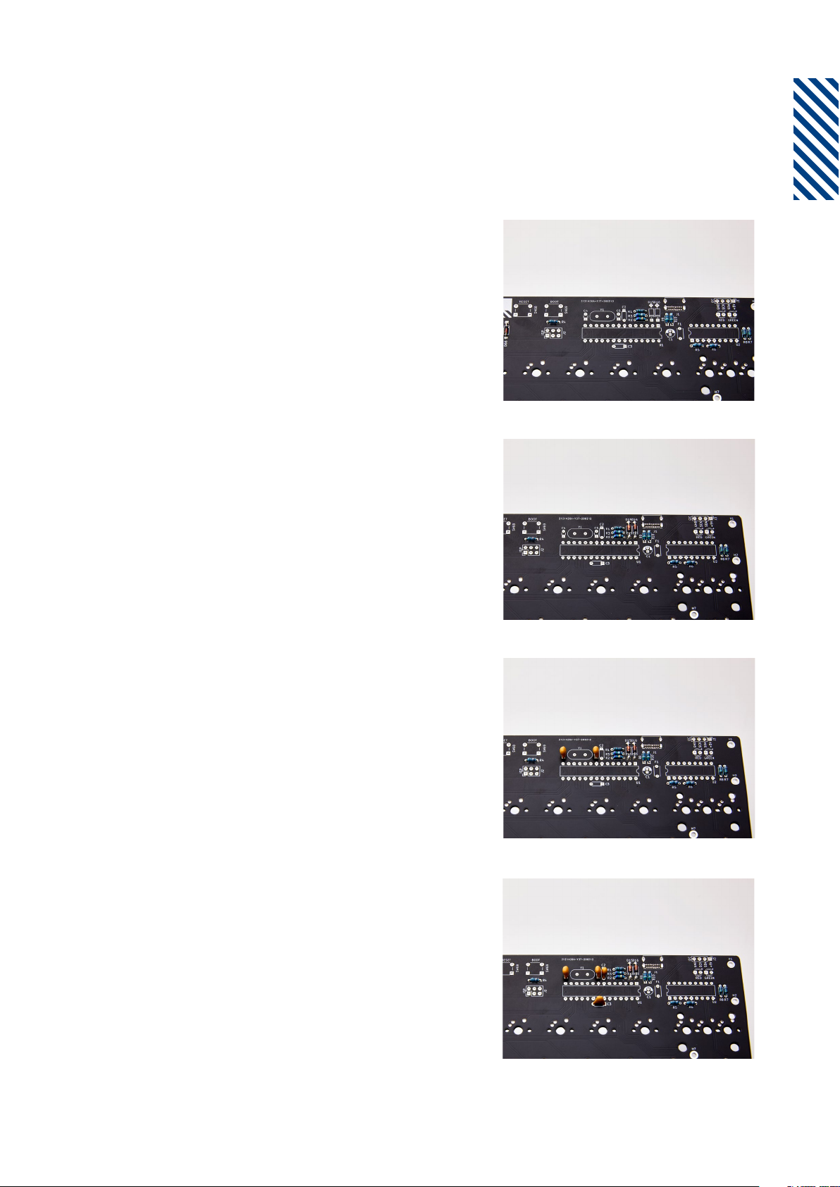
Step 13
Solder the electrolytic capacitor, C1.
Negative (-) goes at the top.
Step 14
Solder the x2 chip sockets. The small one
goes to the U2 and the big one goes to U1,
as in the picture.
Step 15
Solder the LEDs as shown in the picture.
The long leg is the positive.
Step 16
Put the x2 chips in their sockets. The MCU
is pre-programmed with the default ANSI
keymap. Re-programming instructions are
on page 9. The U1 chip’s semi-circle mark
goes to the right. The U2 semi-circle mark
goes to the left. Bend the legs of the chips
inwards to fit in the sockets!