manuals.online logo
Brands
  1. Home
  2. •
  3. Brands
  4. •
  5. YouKits
  6. •
  7. Motherboard
  8. •
  9. YouKits EK-1B Operation instructions

YouKits EK-1B Operation instructions

EK-1B 3 Band CW QRP Transceiver kit
Assemble manual
EK-1B 3 Band CW QRP transceiver kit is easy to build, it has SMD finished by the factory. There are
2pcs of PCB, the main board and display board. To guarantee the building success, the display
board and main board have been assembled and tested including the MCU, LCD and DDS.
EK-1B part list
Name Description QTY Mark
Encoder 1
Volume adjustment 1K with on/off 1 AF/SW
Volume adjustment 1
Q9 mounts 1 ANT
Battery socket 1 BAT
Power jack 1 +V
Headphone jack 2 PHONE、KEY
I-inductance 10uH 1 L3
Electrolytic capacitors 470uF 1 C52
Electrolytic capacitors 100uF 3 C33、C37、C51
Polyester capacitors 0.01 2 C35、C36
Toroid Black core 1 T1
Magnetic inductance Red core 2 L1、L2
enamel insulated wire
red、yellow 0.5meter
each
Transistor 2078 1 Q9
regulator LM2940CT-12 1 Q10
relay EA2-12 2 K1、K2
3mm*8 screw black
Secure 2078 and
regulator 2
3mm nut
Secure 2078 and
regulator 2
3mm*5 screw black Secure enclosure 10 Countersunk head
insulation pad Secure 2078 1
Insulating particles Secure 2078 1
feet 4
Display board Assembled tested 1
Main board SMD finished 1
enclosure 1
3 cores need to made by builder:
Magnetic inductance L1: please use yellow enamel insulated wire, about 15cm, make 9 turns.
Magnetic inductance L2: please use red enamel insulated wire, about 15cm, make 7 turns. As above.
T1 transformer is 8:2, please use red enamel insulated wire, about 15cm, make 8 turns as primary. Use
yellow enamel insulated wire, about 6cm, make 2 turns as secondary. Connect primary to the 2 pads
connected to C7 and Q8, secondary to the pad connected to R28 and ground. As below.
Please install all other parts except Q9 and Q10.
Notice:
1. Please notice the direction of Relay K1 and K2,also the direction of Electrolytic capacitors
C33、C37、C51、C52.
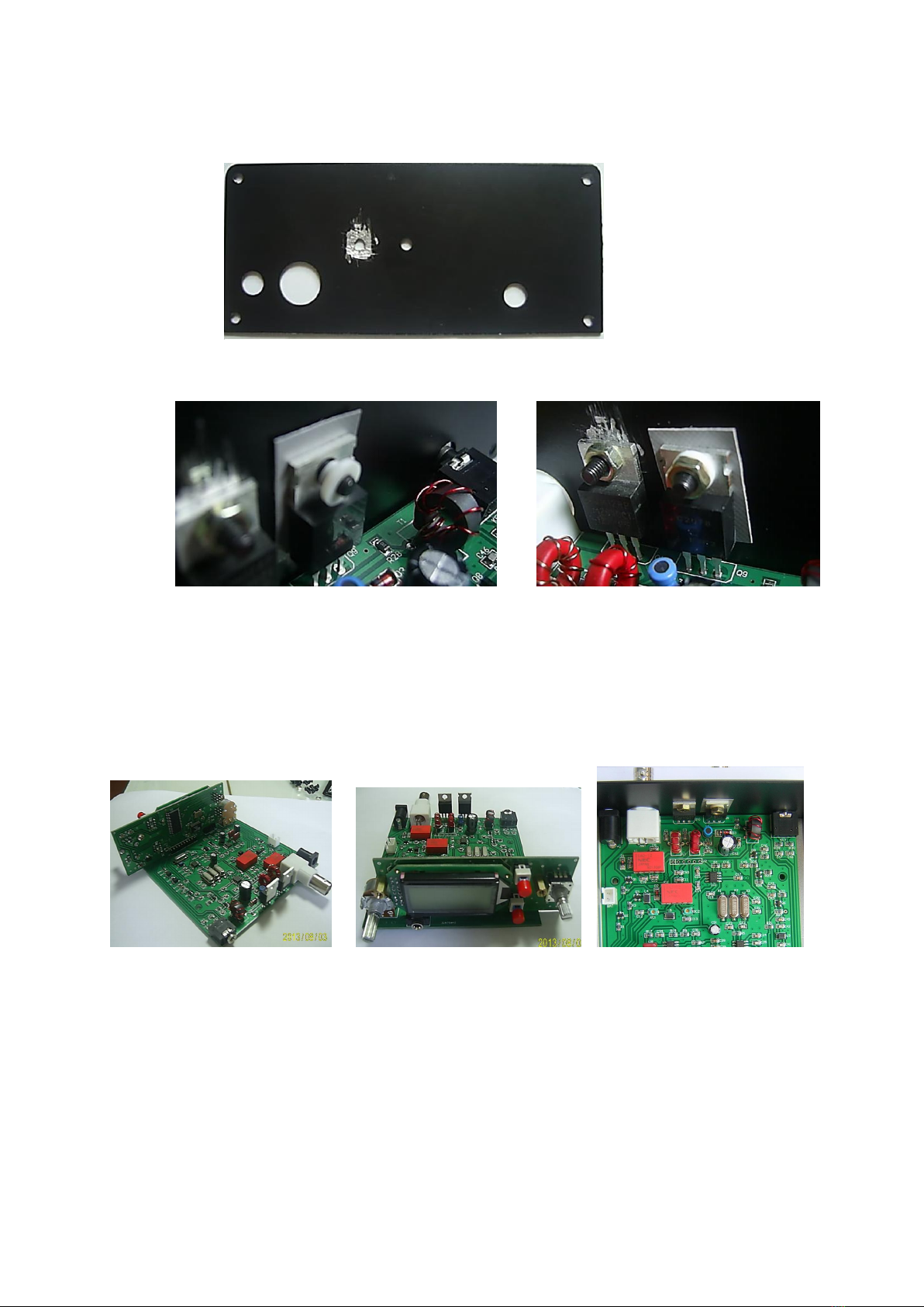
2. Before install Q10, please scratch the install position on the back cover to Q10 has a good surface
contact.
3. After installing all other parts, please install the the back cover and secure the Q9 and Q10,
solder them to the PCB and cut the extra leads. Then secure the Q9, but use insulation pad and
insulating washer then secure Q10, as above.
Testing:
Double check all the soldering point then connect power and turn it on. If the current is around
120mA, it’s OK to proceed. Current higher or lower than 120mA, there are issues that must be corrected
before processing.
Plug your headphone to phone jack, put signal generator to ANT, put generator with a 5uV signal,
adjust frequency to 21.100Mhz or close to this frequency, put EK-1B on same frequency, now adjust
VC3 to receive a 700Hz beat frequency, then adjust VC1 to max the receiver sensitivity.
Adjust signal generator frequency to 14.100Mhz or close to frequency, put EK-1B on same
frequency, now adjust VC2 to max the receiver sensitivity.
Remove the signal generator then connect a dummy load to the antenna connection.
Please plug your key to Key/Paddle jack, test key, if it’s OK then testing finished. Now we can finish
the assemble.
Secure the back cover with screws, put studs on the display board and then secure the front
cover. Install two knobs, assemble finished.
DDS Calibration
DDS has been calibrated in factory, if a calibration is needed, please follow below:
1. Power off, press and push V/M/SAV and RIT/SET then power on, showing below on screen then
release these two buttons.
2. Waiting for 2 second, display change to below. Put your frequency counter to DDS testing point, the
pad close to R27.
Now the frequency counter reading should be same as screen display (10000.00KHz), please adjust
the tune knob if adjustment needed, pressing V/M/SAV for 2 second, the screen display below
release, push V/M/SAV again to end.
The 10 memory position will also be reset back to factory when you do the DDS calibration.
Youkits
2013-8-3

Popular Motherboard manuals by other brands

AOpen MX3W-E3 Online manual

AOpen

AOpen MX3W-E3 Online manual

Biostar H81MGP2 Setup manual

Biostar

Biostar H81MGP2 Setup manual

ASROCK IMB-A1301 Settings guide

ASROCK

ASROCK IMB-A1301 Settings guide

Intel D945PSN Product guide

Intel

Intel D945PSN Product guide

Advantech PCE-7129 user manual

Advantech

Advantech PCE-7129 user manual

Cirrus Logic CRD4610-1 Reference design

Cirrus Logic

Cirrus Logic CRD4610-1 Reference design

EPOX MVP3E specification

EPOX

EPOX MVP3E specification

Biostar M7 VKS Test report

Biostar

Biostar M7 VKS Test report

Abit IC7-G user manual

Abit

Abit IC7-G user manual

Nuvoton NuMaker-M071VG user manual

Nuvoton

Nuvoton NuMaker-M071VG user manual

Micronics M6DPi Pentium Pro manual

Micronics

Micronics M6DPi Pentium Pro manual

American Megatrends Super Voyager PCI-II user guide

American Megatrends

American Megatrends Super Voyager PCI-II user guide

EPOX GXA486SPM manual

EPOX

EPOX GXA486SPM manual

Redpine Signals RS9110-N-11-02 user guide

Redpine Signals

Redpine Signals RS9110-N-11-02 user guide

Asus PCI I-P54NP4 user manual

Asus

Asus PCI I-P54NP4 user manual

Gigabyte GA-7VMM user manual

Gigabyte

Gigabyte GA-7VMM user manual

MSI MPG Z590 GAMING CARBON WIFI quick start

MSI

MSI MPG Z590 GAMING CARBON WIFI quick start

SpinCore Technologies PulseBlaster128 owner's manual

SpinCore Technologies

SpinCore Technologies PulseBlaster128 owner's manual

manuals.online logo
manuals.online logoBrands
  • About & Mission
  • Contact us
  • Privacy Policy
  • Terms and Conditions

Copyright 2025 Manuals.Online. All Rights Reserved.