Yudor YSS -01CK User manual

Multi-function
Control keyboard
USERS MANUAL
YSS-01CK
V3.0

2

3
SAFETY WARNING
nIn
case of failure, be sure to turn off the power or removethe power supply
before contacting service personnel.
n
Toavoid electric shocks, do not disassemble this product on your own. Be sure
to ask a skilled technicianfor the job.
nThe power of this product is
DC
12
V/1.2A. Donotuse othertypes of power
supply, orthe product maybe destroyed orfire canbe triggered.
nKeep unconnected wires, plugs dulyinsulated, or theymightcause short
circuit and damage this product.
nDo NOT connect power to theunit until all installation steps are completed.
Thanks foryourpurchase of ourproduct.
lIn order to make good use of this product, please read this user smanual carefully.
lInorder to use this product correctlyand safely; befamiliar withall operationsteps.
lPlease keep this user smanualfor future reference.
lThe information contained in this document is subject to changeswithout notice.

4
Safety warning
3
Introduction
5
Use instructions
Accessories
5
Front-panel
6
Rear connects line
8
Systemintegration diagram.
9
Instructionofoperation.
10
Remarks
Maintenance & cleaning. 14
Troubleshooting. 14
Optional accessories.
15
Table of Contents

5
Accessories
This product utilizes the most advanced communication protocol. It can integrate
the full series of CCTVproducts produced bySEEKU. The powerful control functions
can effectivelyimprove system efficiency.Large LCD screen make messages easyto
read. Attached with multi directional variable speed joystick makes control operation
easier.
1. Multi function control keyboard
2. RS-485 control connection wiring
3. Power supply
4. User manual
Introduction

6
Keys without a description are not operational in this model.
1.Camera selectionkey.
2.Power LED
3.No function
4.LCD
5.PresetpointCall, Saveand Erase
6.Set up auto pan to the left
7. Set up auto pan to the right
8. Auto Pan LED
9.ExecuteAuto Pan, Executegroupauto cruise, Setdwell time
and cruise speed for group auto cruise
10. Call alarmrecord up Û
11. Call alarmrecord down Ü
Front panel

7
12. Output switch ON/OFF
13. AlarmON/OFF
14. Numberkey
15. Enter key
16. No function
17. Keyboardsystemset up
18. ESCkey
19. OSD manual, esckey
20. OSD manual, Tilt left downÙÜ
21. OSD manual, enter key
22. OSD manual, tilt right downÚÜ
23. Starlightnightvision adjustment
24. Focus
25. zoom
26. Joystick

8
27. Power supplyDC12V
28.RS-232 communication connection socket 6P6C
(not supported bythis model)
29. RS-485 communication connection socket 6P6C
Rear connects line
Pin
RS-232
RS-485
1 XX
2 GND X
3 TxD D-
4 RxD D+
5 XX
6 XX

9
System integration diagram

10
Cam 001
Choose CamID _ _ _
Cam 001
***Right-Up ****
Choose CamID 001
OK !
Cam 001
***ZoomOut ****
Choose CamID:001 OK !
Cam 001
Call Preset No: ___
Cam 001
Save limit Start ?
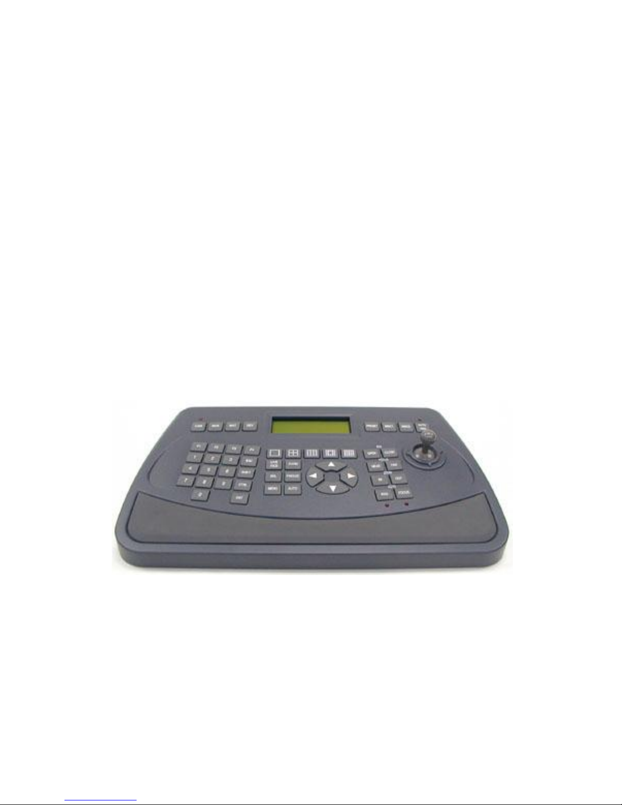
1. Selection of Camera ID.
Press CAM key once and enter the camera ID
selection mode, input camera ID 001 ~ 255,
press ENT key to enter.
Ex: CAM 002 ENT
2. Direction control
Joystick maycontrol 8 directions; Rotation speed can
be variable bycontrolling a joystick.
3. Lens control
Press down FOCUSNEAR/ FAR or ZOOM IN/ OUT
for manual adjustment.
4. Preset position Call, Save, and Clear
Call preset position:
Press PRESET once Input camera ID ENT
Save preset point:
Press PRESET twice Inputcamera ID ENT
Clear preset point:
Press PRESET three times Input camera ID ENT
You can set up 128 preset position, every 32 preset for one group
group 1: 1 ~ 32 /Group 2: 33 ~ 64 /Group 3: 65 ~ 96 /Group 4: 97 ~ 128
5. Pan Limit set up
Pan limit to the left set up : move the camera to pan
limit to the left ,press MISC1 ENT
Pan limit to the right set up : move the camera to pan
limit to the right ,press, MISC2 ENT
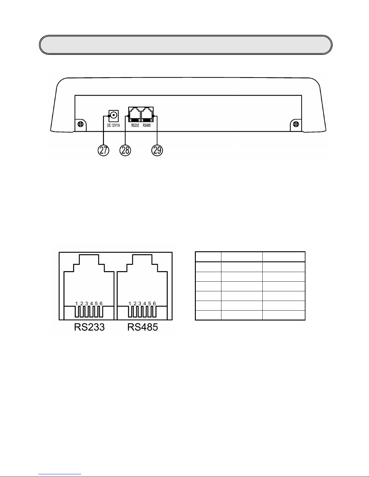
Operation instruction

11
Cam 001
Set Auto Pan ?
Cam 001
Camera OSD Key Ent
6. Execute Auto pan, group auto cruise, auto pan speed set up,
Dwell time set up
Execute auto pan:
AUTO PAN press down 1 time ENT
Execute group auto cruise:
AUTO PAN press down 2 times 1 ~ 5 ENT
Cruise speed set up: AUTO PAN press down 3 times 1 ~ 6 ENT
Dwell time set up: AUTO PAN press down 4 times 00 ~ 99 ENT
Group auto cruise
1 ~ 5
:
1Group auto cruise 1: preset 1 ~ 32 2 Group auto cruise 2: preset 33 ~ 64
3Group auto cruise 3: preset 65 ~ 96 4 Group auto cruise 4: preset 97 ~ 128
5Group auto cruise 5: preset 1 ~ 128
Set up cruise speed
1 ~ 6 :
(means theapproximatedmovement speedfor eachsecond)
110 ゚/sec 220 ゚/sec 330 ゚/sec 440 ゚/sec 550 ゚/sec 660 ゚/sec
Set up dwell time
0 ~ 99 : Second
Input 15 means the dwell time is approximately 15 seconds.
7. Camera OSD manual operation
Camera set up, the set up keys on the front panel
(19 ~ 22) pqtu
uEnter OSD manual / enter
pUp/right
qDown/left
tReturn/ESC
Under thecontrol of keyboard,
Protocol cannot be changed.

12
Cam 001
12 B-001 AL1 2
Cam 001
Enable AlarmNo __
Cam 001
Open Aux No _
8. Alarm set up (DI)
Alarm ON set up:
Press F1 once 1~ 10 ENT
Alarm OFF set up:
Press F1 twice 1 ~ 10 ENT
Alarm
1 ~ 10 correspond to preset position 1 ~ 10
when alarm is triggered, there will be warning siren. Other than the numerical
keys and lens control keys, press any key can stop the warning siren.
9. Output on/off set up (DO)
Camera out put ON set up:
Press F2 once 1 ~ 8 ENT
Camera out put OFF set up:
Press F2 twice 1 ~ 8 ENT
10. Inquiryofalarm record
Inquiryof previous record: F3
Inquiryof previous record: F4
May record the latest 80 alarm information
Display description:
No Any Alarm List, No record of alarm been triggered
12:A-001 AL2, Means the alarm collector 1 point 2 triggered
13:A-001 ALReset, Means alarmcollector 1 allreset
14:B-001 AL1 2, Means the camera s alarm1 and 2 triggered
15:B-001 ALReset, Means camera s alarm reset
12
:
B
-
001 AL1 2
Alarm
no.
Alarm
machine ID.
Equipment type: A-alarm collector / B-camera
Alarm status sequence

13
***System Setup ***
>Clear AlarmList?
>Sure? 0 Yes
1No
11. Keyboard system set up
SHIFT+ CAM enter set up manual
Use the OSD key pqto select the required
set up items
press down uand enter set up mode >Sure? 0: Yes 1: No
Enter 0 (confirmchange) or 1 (no change), and return to previous layer
Press downt/ESC to return to previous /ESC
Set up item:
>ClearAlarmList?
Clear alarm record
>Set Keypad Master?
Set up keyboard as themain control keyboard (needs to be
set up when there are two or more keyboards)
>Set Keypad Slave? Set up keyboard as auxiliary controlkeyboard ((needs to
be set up when there are two or more keyboards)

14
nPrevent water or other materials fall into the keyboard and cause control
abnormal or malfunction.
nDaily cleaning
Use soft cloth to wipe clean.
nRemoval of stubborn stains
The surface of the keyboard is difficult to clean with drycloth. It can be wiped
clean with soft cloth with dilute neutral detergents and then wipe cleanwith soft
dryclothe.
Detergent on the soft cloth shall not penetrate into the gaps between the keys.
nDo not use benzene, diluents orgasoline and othercorrosive solvents
Solvents maydamage the keyboard.
1. Troubled control
a. Is the control wire in poor contact?Is it properlygrounded?Is the wire
interference byother signal?
b. Make sure you use PVC instrument cable (pair type) as the extended control wire?
(For RS-485 control.)
c. Is the control distance too long?Double-check the spec of wire
2. Unsuccessful control
a. Please checks the control wire has properlyconnected or not?
b. Has the camera ID Properly set?Have you selected the correct camera before
operating?
c. Is the protocol match to each other (camera and keypad)? (For RS-485 control )
3. Why the control fails to reach the preset position?
a. Double check is the preset positions innormal operation.
b. Double check the preset positions in a specific group has 2 or more preset
positions.
c. Have you set all the preset position of one group in the same position?
Fortechnical support, please contact the dealer.
Maintenance & cleaning
Troubleshooting

15
Optional accessories
YSS-IR485 IR Control forcamera
lFor RS-485 control system
lExpandable into a simple one-to-multiple
camera
lCompact & lightweight for easyinstallation
lIR remote control ofeasyoperation
lAvarietyofhumane wireless ratio control
features
lApt for use in indoor environments
YSS-2348 232 Signal converter
lFor RS-485 control system
lTo convert RS-232 signals into RS-485 signals
lTo convert PC, DVR control signals
lCompact & lightweight for easyinstallation
lApt for use in indoor environments
YSS-4823 485 Signal converter
lFor RS-485 control system
lTo convert RS-485 signals into RS-232 signals
lApt for all RS-232 communication systems
lThe systemfeatures integrated or extended
control distance
lCompact & lightweight for easyinstallation
lApt for use in indoor and outdoor
environments
YSS-485A 485 signal amplifier
lFor RS-485 control system
lSignal amplification for extended control
distance
lBuilt-in surge protection and scramble signal
resistance
lCompact & lightweight for easyinstallation
lApt for use in indoor environments
This manual suits for next models
1
Table of contents