YUNEEC E20Tvx User manual

E20Tvx User Manual

catalogue)
Product General Description ................................................................................................. 4
Highlights of the E20Tvx camera system: ........................................................................... 4
Overview .................................................................................................................................................4
SEPC ................................................................................................................................... 5
Gimbal Installation ......................................................................................................................... 6
Assembly and Disassembly the X connector gimbals...............................................................6
Assembling .................................................................................................................... 6
Disassembling ............................................................................................................... 6
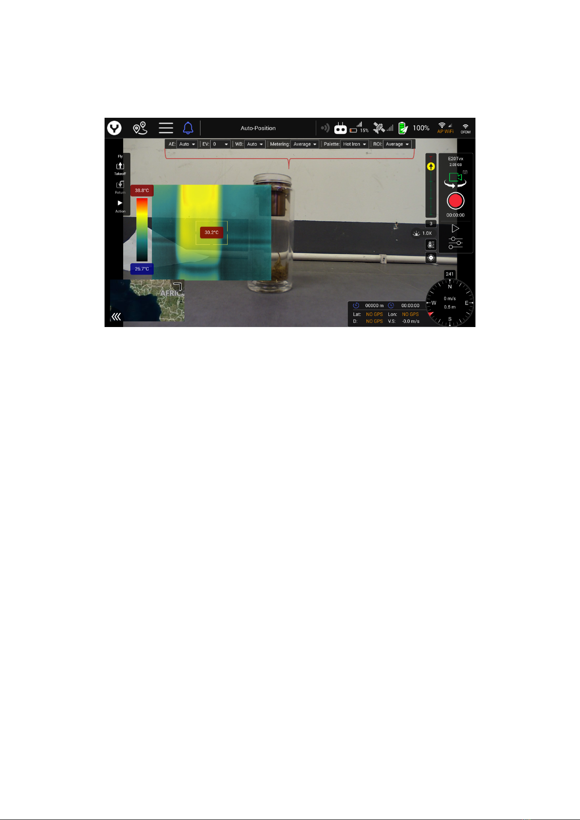
User interface introduction .................................................................................................. 7
Separate introduction of the USER interface ........................................................................... 7
Temperature Bar...................................................................................................................................7
Thermography Video...........................................................................................................................8
Measuring area and Temperature indication..............................................................................8
Gimbal attitude indicator (Tilt and Pan)........................................................................................8
Digital Zoom ratio indicator for Thermography ......................................................................9
Camera quick-access menu...............................................................................................................9
Gimbal type and SD card storage space .....................................................................................9
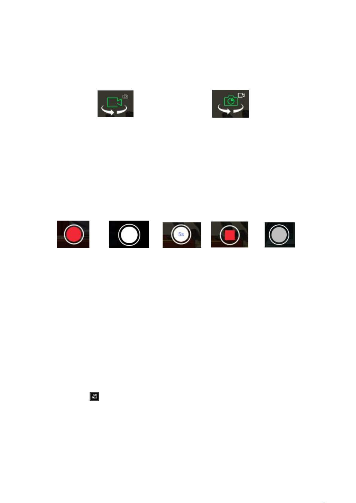
Video/Photo mode switch button................................................................................................ 10
Shutter or Start/Stop recording button ................................................................................... 10
Counter in photo mode/ Timer in video mode ...................................................................... 10
Camera setting menu button ....................................................................................................... 10
Temperature Measurement Range Setting Bar Switch ..................................................... 10
FFC( Flat Field Correction) Button ............................................................................................ 11
Camera setting menu ......................................................................................................... 11
Thermal View Mode.......................................................................................................................... 11
Blend Opacity ................................................................................................................................... 13
Infrared Gain Mode........................................................................................................................... 14
Exposure Mode................................................................................................................................... 14
White Balance ................................................................................................................................... 15

Metering Mode................................................................................................................................... 16
Screen Grid ........................................................................................................................................ 17
Photo mode ........................................................................................................................................ 18
Reset Camera Defaults .................................................................................................................. 18
Format Micro SD card...................................................................................................................... 18
Disclaimer........................................................................................................................... 19

Product General Description
The E20Tvx with Thermography sensor for the H520E Hexacopter is a stabilized 3-axis gimbal,
thermal imaging and residual light camera all-in-one. The E20Tvx is available with a 640*512-pixel
thermal imaging resolution. The E20Tvx takes high-quality pictures and detects more details in
the dark than the naked eye with the help of its large RGB sensor. Thanks to its dual video stream,
you can stream the thermal and residual light image simultaneously to the remote control and
then look at the image as an overlay or picture-in-picture.
Highlights of the E20Tvx camera system:
Thermal imaging camera and 1080p low-light camera combinable and recordable (picture in
picture or overlay).
Te mpe rat ure m ea sureme nt a nd d isplay.
Heat sources are well visualized thanks to the different color spectrums available.
Dual-stream recording allows for separate editing of thermal and RGB video or photo
information.
Overview:

SPEC
Items
E20Tvx
Weight
364g
Angular Vibration Range
±0.03°
Controllable Range
Tilt::-110°~ 30°
Pan: ±165°
Max Angular Velocity
Tilt: 30°/s
Pan: 120°/s
Operating Temperature
-10°C to 50°C
Thermal Sensor Data
Sensitivity
<50mk @F1.0/25°C
Pixel Pitch
12μm
Infrared Wavelength Range
8-14μm
Frequency
25Hz
Photo Formats
JPEG
Video Formats
MP4
Thermal Video Resolution
640x512
Lens
13mm f/1.0, HFOV32°
8.8mm f/1.1, HFOV50.8°
Temperature Measurement
Range
High Gain:-20℃~150℃
Low Gain:100℃~550℃
Visible light Camera Data
Sensor
1/2.8" 2MP
Aperture
F 2.8
Equivalent Focal Length
23mm
Diagonal Fov
89.6°
ISO Range
100~3200
Shutter
1/30s ~ 1/8000s
Video Resolution
1920X1080 60 fps
Photo Formats
JPEG
Video Formats
MP4

Gimbal Installation
Assembly and Disassembly the X connector gimbals
Assembling
Step 1.
Find the Unlocked Mark etched on the Gimbal
Yaw Motor and align the Mark Line with the
front of the damping plate.
Step 2.
Insert the Gimbal Yaw Motor into the
damping plate and rotate it counterclockwise
until the Mark Line of the Locked Mark aligns
with the front of the damping plate to secure
the gimbal.
Step 3.
Remove the lens protector
Disassembling
Step 1.
Hold the gimbal release button and rotate the
Gimbal Yaw Motor clockwise until the Mark
Line of the Unlocked Mark aligns with the
front of the damping plate.
Step 2.
Pull the gimbal out from the damping plate.
Notice: The X-connector series gimbal needn't
bind separately. If the re-binding is needed
please refer to the corresponding section in
the Drone Quick Start Guide.

User interface introduction
1. Temperature Bar
2. Thermography Video
3. Measuring area and Temperature indication
4. Gimbal attitude indicator (Tilt and Pan)
5. Digital Zoom ratio indicator for Thermography
6. Camera quick-access menu
7. Gimbal type and SD card storage space
8. Video/Photo mode switch button
9. Shutter or Start/Stop recording button
10. Counter in photo mode/ Timer in video mode
11. Camera setting menu button
12. Temperature Measurement Range Setting Bar Switch
13. FFC ( Flat Field Correction) Button
Separate introduction of the USER interface
1. Temperature Bar
Show the color separation of different Temperature, which according to the
different Palette selection, the upper the higher temperature is.
The following table shows all palette options
1
2
3
4
5
6
7
8
9
10
11
12
13

White Hot Fulgurite Iron Red Hot Iron Medical Artic Rainbow1
Rainbow2 Tint Black Hot
2. Thermography Video
The Real time video from the E20Tvx displayed on the screen.
3. Measuring area and Temperature indication
The Temperature measure area or spot sight bead, the number in the red rectangle
show the measure result.
The following shows the different sight bead in different ROI mode
ROI mode: Area ROI mode: Spot
In Spot ROI mode, users can measure the temperature of a specified point by
tapping on the thermography area directly.
4. Gimbal attitude indicator (Tilt and Pan)
The Position of the Yellow dot in the gimbal tilt indicator bar shows the gimbal
tilt attitude. The red marks in the bar shows the gimbal is tilted up meanwhile the
green marks shows the gimbal is tilted down. For further accuracy, we can read the
gimbal tilt angle in the rectangle under the Vertical bar.

Also there is a black arrow in the Yellow dot it shows which direction of the gimbal
lens is point to. When the arrow is straight up it shows the gimbal lens is point to
the front of the drone.
5. Digital Zoom ratio indicator
The Logo shows the Thermography video zoom ratio you can use the
right trim button on the ST16E.
Right trim button : Up = zoom in (Step 0.5)
Down= zoom out (Step 0.5)
Right= zoom in (Step 0.2)
Left= zoom out (Step 0.2)
6. Camera quick-access menu
This function can view and change the most important camera parameter settings
in the main interface. To change the setting in quick-access menu, just tap on the
item you want to change, it will pop up a menu for selection.
For example: Change the White balance via the quick-access menu. Tap the WB
Item then select the option your prefer.
Note: the left trim on the ST16E is the Hot key for visible light camera parameter
settings.
Left trim: UP & Down = adjust the EV in the Auto exposure Mode (Step 0.5)
Left & Left = adjust the White balance Mode
7. Gimbal Type and SD card storage space
The H520E can be matched with different gimbal payload. This Indicator shows
which one the drone is carrying, also the SD card storage space.

8. Video/Photo mode switch button
Switch the Camera mode between the Photo mode with the Video recording mode.
Just tap the Icon to switch the Camera work mode
Camera in video mode Camera in Photo mode
9. Shutter or Start/Stop recording soft button
In the Video Recording mode the icon is a red dot. Tap it to start recording the
video and tap again to stop recording.
In the Single Photo mode the icon is a white dot. Tap it to capture a photo
In the Time Lapse Photo mode the icon is a white dot with time interval shown in
the center. Tap it to start the time interval shooting and tap again to stop.
If the SD card is full or the camera without insert the SD card the icon is a gray dot
that means you cannot record anything.
Five different status of the Shutter or Start/Stop recording soft button
Tap to start Tap to record Tap to start Tap to stop No SD card
Recording video one photo time interval Video recording or SD card
Shooting or time interval full
Shooting
10. Counter in photo mode/ Timer in video mode
In the photo mode the counter shows how many photos you have recorder within
one Electrified time .Once you have powered off the drone the number will be reset.
In the video mode the timer shows the time you have recorded in each single video.
11. Camera setting menu button
Tap on this button to switch on the camera setting menu for advance settings
12. Temperature Measurement Range Setting Bar Switch
Tap the button to open the Temperature Measurement Range Setting Bar
Then enable the setting function by switching on the switch on the lower right
corner of the screen.

After the setting function was enabled, users can adjust the temperature
measurement range by sliding the C and H icon on the bar or tap the “+” and “-” of
each side for more precise adjustment.
13. FFC( Flat Field Correction) Button
Tap the button to send the FCC command to the E20Tvx for calibrating
manually.
Camera setting menu
1. Thermal View Mode
There are four different modes can be selected by customer

1) Off: Switch off the thermal view
2) Blend: The thermal view blend with the visible light view
Blend effect
3) Full: Full the thermal view in the screen and you won’t see the visible light view
Full effect
4) Picture in picture: The thermal view in the visible light view
Picture in picture effect

2. Blend Opacity (Thermal View Mode in Blend setting only)
When select the blend thermal view mode the blend opacity bar will show up in the
menu
The customer can slide the slider to adjust the opacity of the thermal view, the
larger the number is the more opacity will be
Blend Opacity 0 effect

Blend Opacity 100 effect
3. Infrared Gain Mode
In High Gain Mode the thermal sensor will have higher temperature measure
accuracy but smaller range (-20℃~150℃)
In Low Gain Mode the thermal sensor will have lower temperature measure
accuracy but larger range (100℃~550℃)
4. Exposure Mode
The exposure mode select menu for visible light Camera
1) Auto: Automatically exposure mode. The camera will handle the exposure
control itself and users can only adjust the Exposure Compensation parameter
in range of ±2 step 0.5.

2) Manual: Users can set the ISO and Shutter speed manually to get the specified
exposure effect.
When Manual exposure mode is selected the menu will add 2 new Items for users
choosing
1: ISO (Range from 100 to 3200)
2: Shutter Speed (Range from 1/30s to 1/8000s)
5. White Balance
The E20Tvx has 7 different white balance for visible light camera can be chosen.
The menu as shown below:

6. Metering Mode
The E20Tvx offers 2 different Metering mode for visible light.
1) Average
In this metering mode, the camera uses light information from the entire scene and
creates an average for the final exposure setting, giving no weighting to any
particular portion of the metered area.
2) Center
Center-weighted metering evaluates the light in the middle of the frame and its
surroundings and ignores the corners.
In the this metering mode the center position will be marked as shown below.

7. Screen Grid
Turn on the screen grid switch, and the gridline auxiliary user composition will
appear on the screen.
Screen Grid effect

8. Photo mode
This item only appears when the camera is in the photo mode
The users can toggle single mode with time lapse mode
1) Single Mode: The camera only records a photo when the shutter button was
pressed.
2) Time Lapse: The camera will record a photo automatically according to the time
interval which set by users
Slide the slider to set the time interval.
9. Reset Camera Defaults
Tap the Reset button and tap yes to confirm, the camera will be reset to the factory
default setting.
10. Format Micro SD card
Tap the Format button and tap yes to confirm, the camera will be format the Micro
SD card.

NOTICE
1 Ensure that the firmware of the gimbal has been updated to the latest version.
2 For the latest product information, please check our official website
www.yuneec.com
WARNING
Do not try to repair the gimbal camera.
Do not expose the lens of the gimbal camera to extreme light sources.
Do not operate the gimbal camera in the rain or in environments with high humidity.
Do not touch or move the gimbal camera until the initialization process has been
completed.
The following special language terms are used throughout the product literature to
indicate various levels of potential harm when operating this product:
NOTICE Procedures, which if not properly followed, create a possibility of property
damage and/or little to no possibility of injury.
CAUTION Procedures, which if not properly followed, create the probability of
property damage and/or a possibility of serious injury.
WARNING Procedures, which if not properly followed, create the probability of
property damage, collateral damage and/or serious injury or create a high probability
of superficial injury.
WARNING
Read the entire instruction manual to become familiar with the features of the product
before operating.
Do not use with incompatible components or alter this product in any way outside o
the instructions provided by Yuneec.
Failure to use this product in the intended manner as described in instruction manual
can result in damage to the product, property and/or cause serious injury
Collection and Processing of Data
Yuneec may collect navigation information such as GPS data to help improve our
products.
We may also collect Depth Map information and Infrared Image information from your
drone delivered to our service center for repair and maintenance service or any other
service.
We may also collect other information such as device information, server log
information, etc. We may also collect personal information used in registration if you
choose to become a registered user and any other information user provided to Yuneec.
We may also collect information which user send to other users, and the recipients and
senders of such information.
We reserve the right to disclose your information if required to do so by law or in the
good-faith belief that such disclosure is needed to comply with applicable laws, for

example in response to a court order, judicial subpoena, warrant or request from
government, or otherwise cooperating with government agencies or law enforcement.
We also reserve the right to disclose your information that we believe in good faith is
necessary or appropriate to:
(i) protect ourselves or others from fraudulent, unlawful, or abusive activities; (ii) take
precautions against potential liability; (iii) protect the security of the Yuneec Apps
embedded into or downloaded onto your drone or any associated
equipment and services; (iv) protect the legal rights of ourselves or any others.
Any information we collected maybe disclosed or transferred to an acquirer, successor
or assignee as part of any potential merger, acquisition, debt financing or other
activities that involves transfer of business assets.
We may make the aggregated non-personal information of the users available to third
parties for various purposes, including (i) complying with various report obligations; (ii)
marketing efforts; (iii) analyzing product safety; (iv) understanding and analyzing our
users’ interests, habits, usage pattern for certain functionalities, services,
content, etc.
Disclaimer
Yuneec International (China) Co., Ltd. cannot be held liable for any damage, injury or
for use of the product in violation with legal regulations, especially in the following
circumstances: Damage and/or injury as well violation of legal regulations resulting
from a failure to comply with the operating instructions or the instructions at
www.yuneec.com, product information, user manual and other legally binding
information.
Damage and/or injury as well violation of legal regulations brought about by the
influence of alcohol, drugs, medication or other narcotics which may impact on the
concentration of the user.
The same applies to illnesses effecting the concentration of the user(dizziness,
tiredness, nausea etc.) or other factors compromising mental and physical capabilities.
Intentionally caused damage, injury or violation of legal regulations.
Any request for compensation caused by an accident resulting from use of the product.
Damage and/or injury as well as violation of legal regulations caused by use of the
product in a no-fly zone, e.g.next to an airfield, above a motorway or a natural
conservation area.
Malfunction of the product caused by retrofitting or replacement with components
which did not come from Yuneec .
Damage and/or injury caused by the use of replica parts (non-original parts).
Damage and/or injury as well as violation of legal regulations caused by incorrect
operation or misjudgment.
Damage and/or injury caused by damaged spare parts or not using original Yuneec
spare parts.
Damage and/or injury as well as violation of legal regulations caused by ignoring the
low voltage battery warning.
Damage and/or injury as well as violation of legal regulations caused by operating the
Other manuals for E20Tvx
1
Table of contents
Other YUNEEC Digital Camera manuals