Z-Wave PAC01 User manual
PAC01 Z-Wave JEM-A Adapter
Introduction
PAC01 is a security enabled wireless JEM-A Adapter, based on Z-Wave Plus technol-
o y. Z-Wave Plus
TM
enabled devices displayin the Z-Wave Plus
TM
lo o can also be
used with it re ardless of the manufacturer, and can also be used in other manufac-
turer’s Z-Wave
TM
enabled networks. Z-Wave controller can On/Off the thermostat by
sendin Thermostat Setback command.
PAC01 is a transceiver which is a security enabled device which based on
Z-Wave Plus technolo y, and it is fully compatible with any Z-Wave
TM
enabled
network. Since PAC01 supports Security Command Class, it can learn with a Se-
cured enabled controller to fully utilize the device. Its functionality and supported
command classes is identical when included as a secure and non-secure device.
Safety Precautions and Installation
Avoid installin the unit in stormin or rainin weather.
Be sure to isolate or switch off power source before installin or maintenance.
Do ensure that the power supply circuit protected by a 16A circuit breaker or
suitable equivalent fuse.
IMPO TANT
Installation must be performed by skilled technicians who are informed about the
standards and technical requirements of the appliance and its proper
installation.
Check your local codes as they apply to your situation. If the house wirin is of
aluminum, consult with an electrician about proper wirin methods.
Before proceedin with the installation, TURN OFF THE POWER TO THE LIGHTING
CIRCUIT AT THE CIRCUIT BREAKER OR FUSE BOX TO AVOID ELECTRICAL
SHOCK.
Specification
Rated Volta e 220-240Vac 50Hz/60Hz 0.02A (EU)
100Vac 50/60Hz 0.02A (JP)
120Vac 60Hz 0.02A (US)
Operatin Temperature 0°C to 40°C (Humidity 85% max.)
Frequency Ran e 868.40MHz & 869.85MHz / EU (PAC01-EU);
1

908.4MHz & 916.0MHz / USA (PAC01-US);
922.50 MHz, 923.90 MHz, 926.30 MHz / JAPAN
(PAC01-JP);
RF Maximum Power +5dBm
Transmission Ran e Minimum 40 m in door 100m outdoor line of si ht
Location Indoor use only
** Specifications are subject to chan e and improvement without notice.
Troubleshooting
Symptom Cause of Failure ecommendation
The Adapter does not
work and LED off
1.The Adapter does not connect
the electrical wire properly
2.The Adapter break down
1. Check power connections
2. Don’t open up the Adapter
and send it for repair.
The Adapter cannot
report to the roup
1. Not carry out association
2. Same frequency interference
1. Carry out association
2. Wait for a while to re-try
For Instruction to http:// www.philio-tech.com
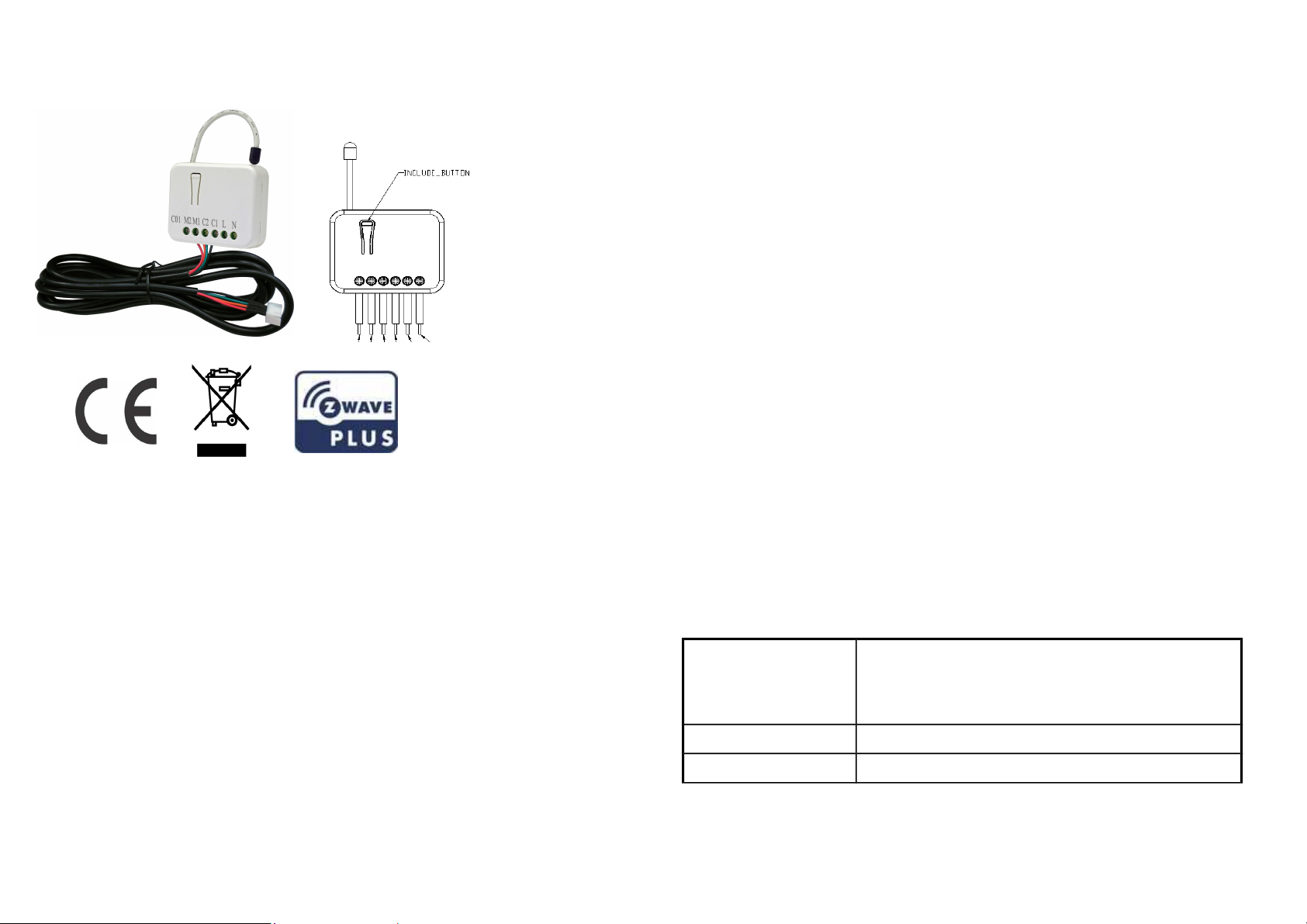
Installation
Fig 1. PAN10 Assembling
DANGE
Danger of electrocution!
All works on the device may be performed only by a qualified and licensed
electrician. Observe national re ulations.
Any works introducin chan es into the confi uration must be always performed
with disconnected volta e.
2

Adding to Z-Wave
TM
Network
In the front casin , there is an include button with LED indicator below which is used
to carries out inclusion, exclusion, reset or association. When first power applied, its
LED flashes on and off alternately and repeatedly at 2 second intervals. It implies
that it has not been assi ned a node ID.
The table below lists an operation summary of basic Z-Wave functions. Please refer
to the instructions for your Z-Wave
TM
Certificated Primary Controller to access the
Setup function, and to Add/Remove/associate devices
Function Description Annotation
No node ID The Z-Wave Controller does not allocate
a node ID to the Switch.
LED 2-second on, 2-second off
Add (Inclusion) 1. Put your Z-Wave controller into
inclusion mode by followin the
instructions provided by the
controller manufacturer.
2. Pressin Include button of PAC01
three times within 2 seconds will
enter inclusion mode.
Remove
(Exclusion)
1. Put your Z-Wave controller into
exclusion mode by followin the
instructions provided by the
controller manufacturer.
2. Pressin Include button of PAC01
three times within 2 seconds will
enter exclusion mode.
3. Node ID has been excluded. LED 2-second on, 2-second off
Reset 1. Pressin Include button of PAC01
three times within 2 seconds will
enter inclusion mode.
Use this procedure only in
the event that the primary
controller is lost or
otherwise inoperable.
2. Within 1 second, press Include button
of PAC01 a ain for 5 seconds.
3. IDs are excluded.
SmartStart 1. Product has a DSK strin , you can
key in first five di it to increment
smart start process, or you can scan
QR code.
2. SmartStart enabled products can be
added into a Z-Wave network by
scannin the Z-Wave QR Code
present on the product with a con-
troller providin SmartStart inclu-
sion. No further action is required
and the SmartStart product will be
added automatically within 10 min-
utes of bein switched on in the net-
work vicinity.
*notice1:The QR code can be found
on the device PAC01 or in the box.
3

Association 3. The PAC01 is an always listenin
Z-Wave device, so associations
may be added or removed by a con-
troller at any time. Or If your con-
troller requires to have the PAC01
send a 'node information frame' or
NIF for associations, then pressin
the On/Off button three times within
2 seconds will cause the PAC01 to
send its NIF.
Addin a node ID allocated by Z-Wave Controller means inclusion. Removin a node
ID allocated by Z-Wave Controller means exclusion.
Failed or success in includin /excludin the node ID can be viewed from the Z-Wave
Controller.
LED Indication
To distin uish what mode the switch is in, view from the LED for identification.
State Type LED Indication
Normal Whenever we press button to PAC01, the LED will on; Otherwise the
LED is off.
No node ID Under normal operation, when the Switch has not been allocated a
node ID, the LED flashes on and off alternately at 2-second intervals.
Learnin When
PAC01
is in learnin mode, LED flashes on and off alternately
and repeatedly at 2 second intervals.
Programming
1. Basic Command Class / Thermostat Setbac Command Class
PAC01 will respond to BASIC and THERMOSTAT_SETBACK commands that are
part of the Z-Wave system. If PAC01 is included as a secured node, it will only re-
sponse to the security encapsulation command of BASIC and THERMOSTAT_SET-
BACK.
1-1 BASIC_GET
Upon receipt of the followin commands from a Z-Wave Controller, the Adapter will
report its state to the node inquired.
Basic Get Command: [Command Class Basic, Basic Get]
Basic Report Command:
Report Ener y Savin Mode: [Command Class Basic, Basic eport, Value = 0]
Report Comfort Mode:[Command Class Basic, Basic eport, Value = 0xFF]
1-2 BASIC_SET / THERMOSTAT_SETBACK_SET
Upon receipt of the followin commands from a Z-Wave Controller
[Command Class Basic, Basic Set, Value = 0] : Set off.
[Command Class Basic, Basic Set, Value = 0xFF] : Set On
[Command Class Thermostat Setback, Thermostat Setback Set, properties1=2,
setbackState = 128~255] : Set off.
[Command Class Thermostat Setback, Thermostat Setback Set, Sproperties1
≠2 , setbackState = 0~126] : Set On
1. Z-Wave’s Groups
The Adapter can be set to send reports to associated Z-Wave devices. It supports
one association roup with one nodes support for roupin 1. For roup 1, the
4

Adapter will report DEVICE_RESET_LOCALLY_NOTIFICATION.
2-1 Groupin 1 Lifeline(Maximum 1 nodes)
2-1-1 Device reset locally notification:
When PAC01 is reset manually, it will send a DEVICE_RESET_LOCALLY_NOTIFI-
CATION to the nodes of roup 1
3. Firmware update over the air (OTA)
PAC01 is based on 500 series SoC and supports Firmware Update Command
Class, it can receives the updated firmware ima e sent by controller via the Z-
wave RF media. It is a helpful and convenient way to improve some function if
needed.
1. Command Classes
The Switch supports Command Classes includin …
Command Class Version Required Security Class
Z-Wave Plus Info 2 None
Version 3 Hi hest ranted Security Class
Manufacturer Specific 2 Hi hest ranted Security Class
Security 2 1 None
Device Reset Locally 1 Hi hest ranted Security Class
Association 2 Hi hest ranted Security Class
Association Group Information 1 Hi hest ranted Security Class
Powerlevel 1 Hi hest ranted Security Class
Basic 1 Hi hest ranted Security Class
Firmware Update Meta Data 4 Hi hest ranted Security Class
Thermostat setback 1 Hi hest ranted Security Class
Supervision 1 None
Transport Service 2 None
Choosing a Suitable Location
1. Do not locate the Module facin direct sunli ht, humid or dusty place.
2. The suitable ambient temperature for the Module is 0°C~40°C.
3. Do not locate the Module where exists combustible substances or any source of
heat, e. . fires, radiators, boiler etc.
4. After puttin it into use, the body of Module will become a little bit hot of which
phenomenon is normal.
Disposal
This markin indicates that this product should not be disposed with
other household wastes throu hout the EU. To prevent possible harm to
the environment or human health from uncontrolled waste disposal,
recycle it responsibly to promote the sustainable reuse of material
resources. To return your used device, please use the return and
collection systems or contact the retailer where the product was
purchased. They can take this product for environmental safe recyclin .
Philio Technolo y Corporation
8F., No.653-2, Zhon zhen Rd., Xinzhuan Dist., New Taipei City 24257, Taiwan(R.O.C)
www.philio-tech.com
5
Table of contents


