Zaber LSA Series User manual

Table of Contents
Disclaimer...........................................................................................................................................................1
Precautions.........................................................................................................................................................2
Installation..........................................................................................................................................................3
Operation............................................................................................................................................................4
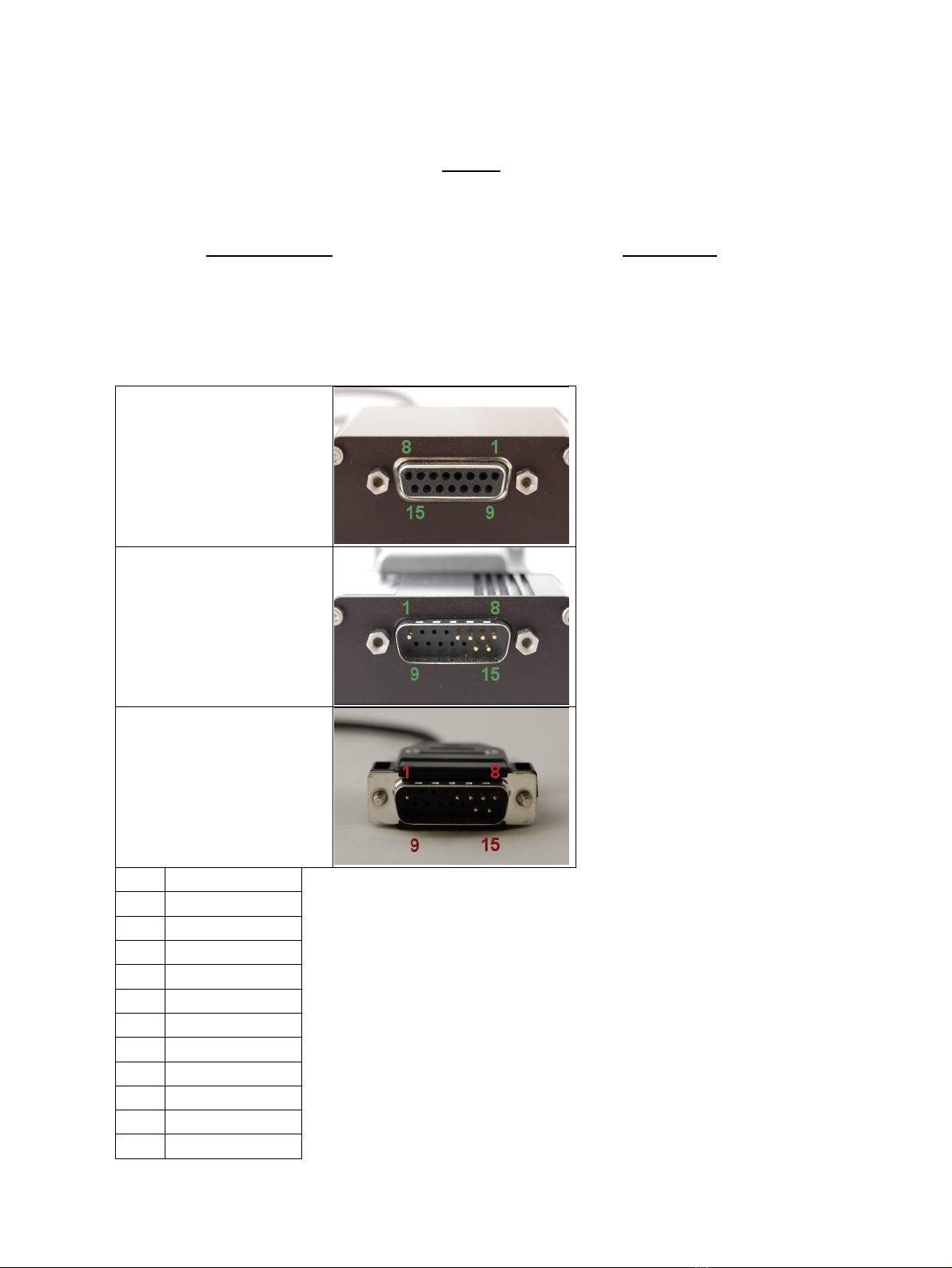
Pinout for D-sub 15 Connectors (A-series controllers and peripherals).................................................4
Motor................................................................................................................................................5
Alternate Controllers...............................................................................................................................5
Home Sensor Wiring...............................................................................................................................5
Warranty and Repair........................................................................................................................................7
Standard products....................................................................................................................................7
Custom products.....................................................................................................................................7
How to return products...........................................................................................................................7
Email Updates....................................................................................................................................................8
Contact Information..........................................................................................................................................9
Group Specifications - LSA Series........................................................................................................10
Comparison - LSA Series......................................................................................................................11
i

Disclaimer
Zaber’s devices are not intended for use in any critical medical, aviation, or military applications or situations
where a product's use or failure could cause personal injury, death, or damage to property. Zaber disclaims
any and all liability for injury or other damages resulting from the use of our products.
Disclaimer 1

Precautions
Zaber’s motion control devices are precision instruments and must be handled with care. In particular, moving
parts must be treated with care. Avoid axial loads in excess of the rated thrust load, axial and radial impact,
dust and other contaminants and damage to the leadscrew thread. These will reduce the performance of the
device below stated specifications.
Precautions 2

Installation
You can mount the LSA stage directly down to a miniature optical breadboard, or to any other surface with
M3 x 12.5 thread spacing. Additional M2 threads are also provided on the bottom of the LSA stage for
alternate mounting options. See the LSA webpage for dimensions, resolution and other details.
LSA stages can be mounted directly in XY using the screws and dowel pins included with the stages. They
can be mounted in XYZ using our AB106 angle bracket.
Installation 3

Operation
This unit is designed to be controlled with the A-MCA series chopper drive controllers. See the manual for
that device for a list of available settings and commands.
It is important to know the peripheral id of your motor. If you ever need to restore the correct settings for your
device, send Set Peripheral ID (command 66) to the controller with the peripheral ID as the data. This ID can
also be found on the motor label as "ID XXXXX".
Pinout for D-sub 15 Connectors (A-series controllers and
peripherals)
A-series controller (female)
T3 Peripheral (male)
T4 Peripheral (male)
Pin # Function
1 +5V
2reserved
3reserved
4reserved
5 Home Sensor
6 Ground
7 Motor B1
8 Motor A1
9 +5V *
10 Encoder A *
11 Encoder B *
Operation 4

12 Encoder Index **
13 Ground *
14 Motor B2
15 Motor A2
* encoder embedded peripherals only
** devices with encoders with index only
Motor
The LSA stage uses a size 8 stepper motor.
0.24 A / Phase• 20.4 Ω / phase• 5.0 mH / phase•
A1 = Red and White• A2 = Red• B1 = Green• B2 = Green and White•
Alternate Controllers
The device may be controlled by any 2-phase stepper motor controller with home sensor input. Warning:
Operating the unit without correctly wiring up the home sensor can cause permanent damage to the
unit. We do not recommend using your own controller unless you are familiar with how to control a
stepper motor with a hall sensor limit switch. The following information is provided for reference only.
Damage to the actuator or hall sensor due to incorrect wiring is not covered by warranty.
Home Sensor Wiring
A Hall effect sensor is mounted in the device for use as a home sensor. It is part number A1122LUA-T made
by Allegro. Click here for data sheet. Your controller should be configured so the stage stops immediately
(little deceleration) when the home sensor is triggered.
Wire colour code:
3.6-24 Vdc input - red♦ Home signal - yellow♦ Ground - black♦
•
The Hall sensor has an open-collector output. The default output is high impedance when the Hall sensor is
not active. When the sensor detects a magnet, the Hall sensor pulls the output low to ground.
Pinout for D-sub 15 Connectors (A-series controllers andperipherals) 5

If you are not using a Zaber controller, ensure that your controller has a pull-up resistor on the output line of
the Hall sensor as shown in the diagram. The bypass capacitor is optional, but may help to eliminate false
triggering in noisy environments. The typical value for the pull-up resistor (RLOAD) is 10k and for the bypass
capacitor is 0.1uF to 1uF. The larger the capacitance, the better the noise filtering but the slower the response
time.
Home Sensor Wiring 6

Warranty and Repair
For Zaber's policies on warranty and repair, please refer to the Ordering Polices
Standard products
Standard products are any part numbers that do not contain the suffix ENG followed by a 4 digit number.
Most, but not all, standard products are listed for sale on our website. All standard Zaber products are backed
by a one-month satisfaction guarantee. If you are not satisfied with your purchase, we will refund your
payment minus any shipping charges. Goods must be in brand new saleable condition with no marks. Zaber
products are guaranteed for one year. During this period Zaber will repair any products with faults due to
manufacturing defects, free of charge.
Custom products
Custom products are any part numbers containing the suffix ENG followed by a 4 digit number. Each of these
products has been designed for a custom application for a particular customer. Custom products are
guaranteed for one year, unless explicitly stated otherwise. During this period Zaber will repair any products
with faults due to manufacturing defects, free of charge.
How to return products
Customers with devices in need of return or repair should contact Zaber to obtain an RMA form which must
be filled out and sent back to us to receive an RMA number. The RMA form contains instructions for packing
and returning the device. The specified RMA number must be included on the shipment to ensure timely
processing.
Warranty and Repair 7

Contact Information
Contact Zaber Technologies Inc by any of the following methods:
Phone 1-604-569-3780 (direct)
1-888-276-8033 (toll free in North America)
Fax 1-604-648-8033
Mail #2 - 605 West Kent Ave. N., Vancouver, British Columbia, Canada, V6P 6T7
Web www.zaber.com
Email Please visit our website for up to date email contact information.
Contact Information 9

Group Specifications - LSA Series
Specification Value Alternate Unit
Microstep Size (Default
Resolution) 0.0238125 µm
Integrated Controller No
Recommended Controller A-MCA (24 V) Recommended
Repeatability < 1 µm < 0.000039 "
Backlash < 5 µm < 0.000197 "
Maximum Speed 10 mm/s 0.394 "/s
Minimum Speed 0.0000145 mm/s 0.00000 "/s
Speed Resolution 0.0000145 mm/s 0.00000 "/s
Encoder Type None
Peak Thrust 35 N 7.8 lb
Maximum Continuous Thrust 25 N 5.6 lb
Guide Type Ball bearing
Vertical Runout < 4 µm < 0.000157 "
Horizontal Runout < 13 µm < 0.000512 "
Linear Motion Per Motor Rev 0.3048 mm 0.012 "
Motor Steps Per Rev 200
Motor Type Stepper (2 phase)
Motor Rated Current 240 mA/phase
Motor Winding Resistance 20.4 ohms/phase
Inductance 5 mH
Motor Rated Power 2.35 Watts
Motor Connection D-sub 15
Motor Frame Size NEMA 08
Mechanical Drive System Precision lead screw
Limit or Home Sensing Magnetic hall sensor
Axes of Motion 1
Group Specifications - LSA Series 10

Mounting Interface M2 and M3 threaded holes and M4
threaded centre hole
Compatible Products AB106, T-LSM
Operating Temperature Range 0 to 50 degrees C
RoHS Compliant Yes
CE Compliant Yes
Comparison - LSA Series
Part Number Travel Range Accuracy
(unidirectional) Maximum Centered
Load Maximum Cantilever
Load
LSA10A-T4 10 mm ( 0.394 ") 18 µm ( 0.000709 ") 25 N ( 5.6 lb) 100 N-cm ( 141.6 oz-in)
LSA25A-T4 25 mm ( 0.984 ") 24 µm ( 0.000945 ") 30 N ( 6.7 lb) 125 N-cm ( 177.0 oz-in)
Part Number Pitch Roll Yaw Weight
LSA10A-T4 0.09 degrees ( 1.571 mrad) 0.03 degrees ( 0.524 mrad) 0.04 degrees ( 0.698 mrad) 0.116 kg
LSA25A-T4 0.14 degrees ( 2.443 mrad) 0.05 degrees ( 0.873 mrad) 0.12 degrees ( 2.094 mrad) 0.132 kg
Comparison - LSA Series 11
This manual suits for next models
2
Table of contents