1 Contents
Elsner Elektronik GmbH • Sohlengrund 16 • 75395 Ostelsheim • Germany
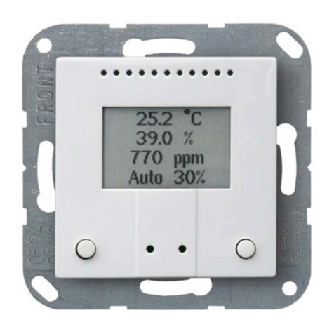
Sensor KNX T-L-Pr-UP Touch
Version: 17.09.2020 • Technical changes and errors excepted.
1. Description ........................................................................................... 5
1.0.1. Scope of delivery .......................................................................................... 5
1.1. Technical data ........................................................................................................... 5
1.1.1. Accuracy of the measurement ..................................................................... 6
2. Installation and commissioning ........................................................... 7
2.1. Installation notes ...................................................................................................... 7
2.2. Installation location .................................................................................................. 7
2.2.1. Detection range of the presence sensor ..................................................... 8
2.3. Device structure ........................................................................................................ 9
2.3.1. Housing .......................................................................................................... 9
2.4. Installing the sensor ............................................................................................... 10
2.5. Notes on mounting and commissioning .............................................................. 10
3. Addressing of the device at the bus .................................................. 10
4. Maintenance ....................................................................................... 10
5. Disposal ............................................................................................. 11
6. Transfer protocol ............................................................................... 12
6.1. List of all communication objects ......................................................................... 12
7. Parameter setting .............................................................................. 16
7.1. Behaviour on power failure/ restoration of power .............................................. 16
7.2. General settings ..................................................................................................... 16
7.3. Brightness Measurement ...................................................................................... 16
7.4. Brightness threshold value .................................................................................... 17
7.4.0.1. Threshold value ............................................................................ 17
7.4.0.2. Switching output .......................................................................... 18
7.4.0.3. Block .............................................................................................. 18
7.5. Motion detector ...................................................................................................... 19
7.5.1. Master 1/2 .................................................................................................... 21
7.5.2. Align communication between master and slave .................................... 24
7.5.2.1. Sending cycle slave - switch-off delay master ........................... 24
7.5.2.2. Slave cycle reset ........................................................................... 24
7.6. Temperature Measurement ................................................................................... 25
7.7. Buttons .................................................................................................................... 26
7.7.1. Pushbutton left / right ................................................................................. 26
7.8. LEDs ......................................................................................................................... 31
7.9. Logic ........................................................................................................................ 31
7.9.0.1. AND logic ....................................................................................... 32
7.9.0.2. OR logic ......................................................................................... 32
7.9.1. AND logic 1+2 and OR logic outputs 1+2 .................................................. 32
7.9.1.1. Block .............................................................................................. 33
7.9.1.2. Monitoring ..................................................................................... 34
7.10.AND logic connection inputs ................................................................................ 34


