INTRODUCTION
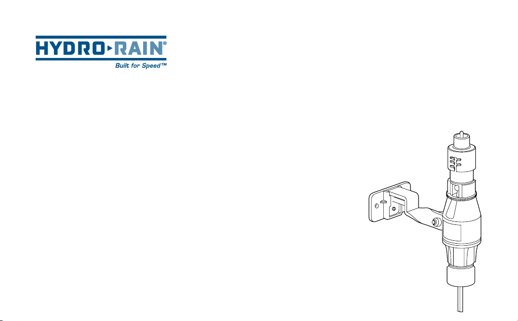
Thank you for selecting the HRC-990-RS-MD Hydro-Rain®sensor module. This
sensor is built for use with the Hydro-Rain®HRC-990 isolation controller only. It
is equipped with a wire plug in feature that inserts directly into the base of the
HRC-990 (See front cover illustration). After a set amount of rain has fallen the
sensor engages a switch that will prevent the timer from watering. The added
freeze sensor bonus feature will provide peace of mind by interrupting your
sprinklers controlled by the HRC-990 timer and reduce the hazards of stand-
ing water freezing on your driveway, sidewalks, and patios when temperatures
drop below 37˚F (3˚C). Once the rain sensor has dried sufficiently or the freeze
sensor temperature rises above 37˚F (3˚C), the sensor allows normal sprinkler
operation.
INSTALLATION INSTRUCTIONS
Mounting
The HRC-990-RS-MD sensor includes 3 mounting options.
1. ½" Slip Adapter for mounting on a PVC riser
2. ½" Threaded Adapter for mounting on a PVC or metal threaded riser
3. Rain Gutter or flat surface adapter
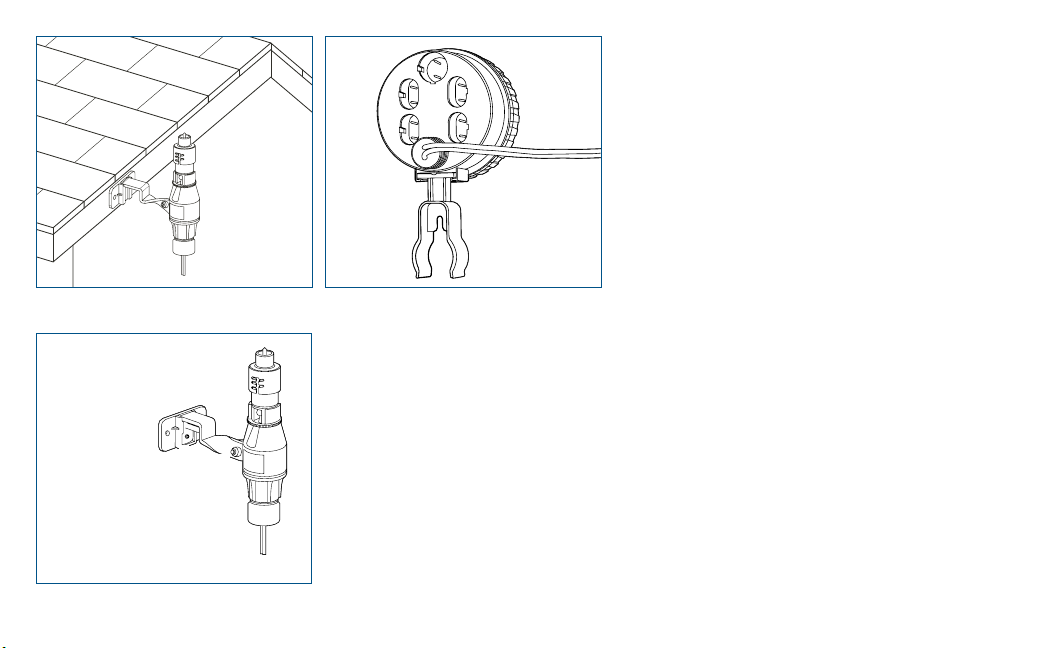
Mount the sensor where it will be exposed to direct, unobstructed rainfall
(but away from sprinkler spray). The switch-housing portion must be upright
(see Figure 1).
Hints for mounting:
A. Because the wire provided with the module is 30’ long. You must install the
sensor within 30’ of the timer.
B. Mount in the highest possible position where rain can fall directly upon the
sensor.
C. As described in the “Adjustments and Operation” section of this manual,
“reset rate” refers to the amount of time it takes the sensor to dry out suffi-
ciently for the sprinkler system to be allowed to come back on. The mounting
location will affect this rate and should be taken into consideration should
extreme conditions exist. For example, mounting the sensor on a very sunny,
southeastern end of a building may cause the sensor to dry out sooner than
desired. Similarly, mounting on the northern end of a building with constant
shade may keep the sensor from drying soon enough. Some experimentation
and use of the “vent ring” (as described later) will usually yield satisfactory
results.
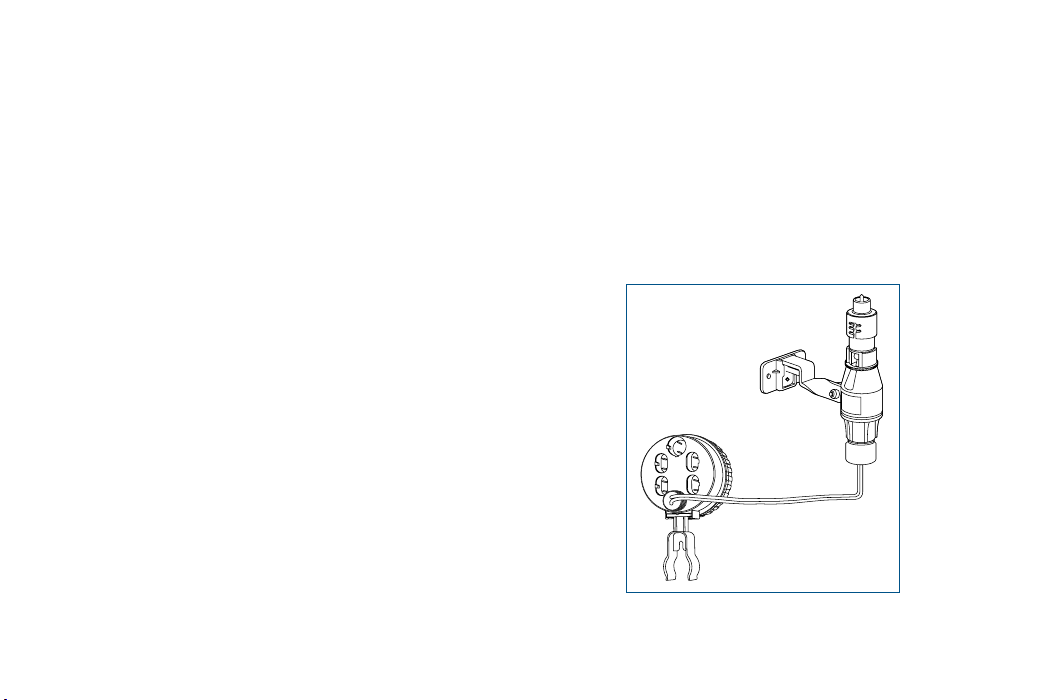
Once the sensor is mounted, run the wire and wiring jack to the HRC-990 timer.
Plug the jack into the base of the timer marked “Sensor” . The rain sensor is
now ready for use. (See Figures 2 and 3)
Wiring
Important: The sensor is sold and designed for for use with the HRC-990 timer
only. Any alteration of this product for use with 24 Volt irrigation timers voids the
warranty.
OPERATION CHECK TO VERIFY CORRECT WIRING
Turn on one zone of the sprinkler system that is visible while you are in reach
of the sensor. Manually depress the spindle at the top of the sensor until you
hear the switch “click” off. The sprinkler zone should stop instantly. If it does
not, check wiring jack to insure proper contact is made with the HRC-990 base.
ADJUSTMENTS AND OPERATION
The sensor can keep the irrigation system from starting or continuing after
rainfall quantities of ¹⁄8", ¼", ½", ¾", or 1". To adjust to the desired quantity of
rainfall, rotate the cap on the switch housing so that the pins are located in the
proper slots (See Figure 4). Do not forcibly twist the cap as this might break the
pins. The time that it takes the sensor to reset for normal sprinkler operation
after the rain has stopped is determined by weather conditions (wind, sunlight,
humidity, etc.). These conditions will determine how fast the hygroscopic discs
dry out, and since the landscape is also experiencing the same conditions, their
respective drying rates will roughly parallel each other. There is an adjustment
capability on the sensor that will slow down the reset rate. By turning the “vent
ring” (See Figure 4) to completely or partially cover the ventilation holes, the
hygroscopic discs will dry more slowly. This adjustment can compensate for an
“overly sunny” installation location or peculiar soil conditions. Experimenting
with the vent rings will best determine the ideal vent setting.
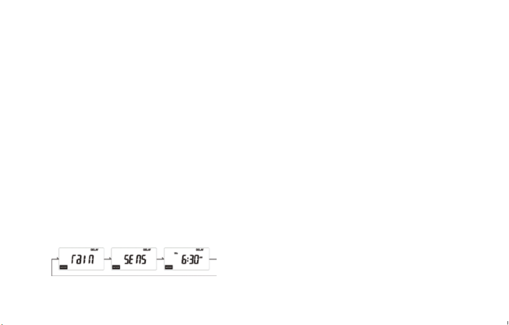
DISPLAY
When the optional Rain/Freeze Sensor is installed with the HRC-990 Hydro-
Rain®timer and the unit is operating under <DELAY>, <AUTO> or <MANUAL>
mode, the unit will enter a special <RAIN DELAY> operation where the LCD will
display the following:
FREEZE SENSOR OPTION
The temperature at which the optional freeze off sensor feature is activated is
37°F ±2° (3°C ±1°) (temperature range adjustment is not available).
BYPASSING THE SENSOR
Should you desire to bypass the operation of the sensor for any reason
(i.e., turn on your system even though the sensor has shut “off” due to rainfall or
temperature), unplug the sensor from the bottom of the timer. Plug it back in to
resume normal sensor operation.
MAINTENANCE
There is no required maintenance for the unit. The sensor does not have to be
removed or covered for winterizing purposes. All parts are easily replaceable if
they become damaged or lost. The spindle assembly is designed to stay with the
cap. Do not pull them apart.
TROUBLESHOOTING
Follow these simple checks before replacing your sensor:
System will not come on at all:
A. Check to see that the sensor discs are dry and the switch “clicks” on and off
freely by pressing the top of the spindle.
B. Look for breaks in the wire leading to the sensor and check all wire junctions.
System will not shut off even after heavy rainfall:
A. Check wiring for correct installation. (See “Operation Check to Verify
Correct Wiring”.)
B. Check sensitivity setting on sensor, and move the cap to a more
sensitive setting. The sensor is an accurate rain gauge and can be
verified by setting up a “tube” type rain gauge in the same vicinity and
making periodic readings.
C. Check for obstructions to rainfall such as overhangs, trees or walls.
1
2
3
4
SOLAR
RAIN/
FREEZE
SENSOR
Figure 2