Zenoah PSZ2610 User manual

PSZ2610
OWNER’S MANUAL
POLE SAW
115 40 43-38 (011)
G
B

GB-2
PSZ2610
This pole-mounted powered pruner (hereafter called pruner) is designed especially for tree service
by a trained operator. For safe operation, you must read and understand this owner's manual com-
pletely before operating the pruner.
Note: Illustrations and specifications in this manual may vary according to requirements of individual
countries and are subject to change without notice by the manufacturer.
1. Parts location
SAFETY FIRST
Instructions contained in warnings within this manual marked
with a symbol concern critical points which must be taken into
consideration to prevent possible serious bodily injury, and for
this reason you are requested to read all such instructions care-
fully and follow them without fail.
WARNINGS IN THE MANUAL
WARNING
This mark indicates instructions, which must be followed in order
to prevent accidents, which could lead to serious bodily injury
or death.
IMPORTANT
This mark indicates instructions, which must be followed, or it
leads to mechanical failure, breakdown, or damage.
NOTE
This mark indicates hints or directions useful in the use of the
product.
Contents
1. Parts location ...................................................2
2. Specifications...................................................3
3. Warning labels on the machine .......................3
4. Symbols on the machine..................................3
5. For safe operation ............................................4
6. Set up...............................................................7
7. Fuel and chain oil.............................................9
8. Operation .......................................................10
9. Maintenance ..................................................13
10. Storage...........................................................16
11. Disposal .........................................................16
12. Troubleshooting guide ...................................16
1. Primer
2. Air cleaner cover
3. Choke lever
4. Fuel tank
5. Starter knob
6. Spark arrester
7. Transmission
8. Chain cover
9. Saw chain
10. Guide bar
11. Grip
12. Shaft tube
13. Suspension point
14. Throttle trigger
15. Stop switch
16. Throttle cable
17. Throttle set button
18. Guide bar cover
19. Hexagon socket (S16/
S19) with torx driver
20. Wrench
21. Spanner
22. Screw driver
23. Harness
24. Goggles
25. Owners’ manual

GB-3
PSZ2610
G
B
2. Specication
3. Warning labels on the machine
Never modify your machine.
We won’t warrant the machine, if you use
the
remodeled pruner or if you don’t observe
the proper usage written in the manual.
If warning label peels off or becomes soiled
and impossible to read, you should contact the
dealer from which you purchased the product
to order new labels and affix them in the re-
quired location(s).
(1) Read owner's manual before operating this
machine.
(2) Wear head, eye and ear protection.
(3) Warning/Attention
(4) The unit has not been designed to provide pro-
tection from electric shock in the event of con-
tact with overhead electric lines.
MIN MAX
The port to refuel the “MIX GASOLINE”
Position: FUEL TANK CAP
The direction to close the choke
Position: AIR CLEANER COVER
The direction to open the choke
Position: AIR CLEANER COVER
If you turn the rod by screwdriver follow the arrow to the “MAX” position, the chain oil flow more,
and if you turn to the “MIN” position, less.
Position: Bottom of the TRANSMISSION
For safe operation and maintenance, symbols are carved in relief on the machine. According to these indications,
please be careful not to make a mistake.
4. Symbols on the machine
PSZ2610
Overall size (L x W x H) ..............2085 x 250 x 310mm
Dry weight........................................................... 5.5kg
Engine Type.................. Air-cooled 2-stroke gasoline
Model.................................... Zenoah GZ25N
Displacement .................................. 25.4cm3
Max. output. 1.2Hp (0.9kW) at 7500min-1(rpm)
Idle speed ................... 3000±200min-1(rpm)
Fuel................... Mixture (Gasoline 50 : Oil 1)
(when using ZENOAH genuine oil)
Carburetor .............. Walbro Diaphragm type
Spark plug ................................NGK CMR7H
Fuel tank capacity............................................... 0.65
Transmission ........ Centrifugal clutch, Rigid driveshaft
Reduction ratio .................................................... 0.94
Cutting head
Guide bar Type............. OREGON DOUBLE GUARD
Size.................................... 10(25) in.(cm)
Saw chain Type.......................... OREGON 90SG39X
Pitch x Gauge. 3/8x0.043 (9.53 x 1.07) in.(cm)
Sprocket ................................................................. 7T
Oil pump ..................................................Plunger type
Standard Accessories
Harness .............................................................. 1 pc.
Tool Kit ................................................................ 1 pc.
Guide bar cover.................................................. 1 pc.
Goggles .............................................................. 1 pc.
Specifications are subject to change without notice.

GB-4
PSZ2610
1. Read this manual carefully until you
completely understand and follow all
safety and operating instructions.
2. Keep this manual handy so that you
may refer to it later whenever any
questions arise. Also note, if you have
any questions which cannot be an-
swered herein, contact the dealer from
whom you purchased the product.
3. Always be sure to include this manu-
al when selling, lending, or otherwise
transferring the ownership of this
product.
4. Never allow children or anyone unable
to fully understand the directions
given in the manual to use the ma-
chine.
WORKING CONDITION
1. When using the product, you should
wear proper clothing and protective
equipment.
(1) Helmet
(2) Ear protectors
(3) Protection goggles or face protec-
tor
(4) Thick work gloves
(5) Non-slip-sole work boots
2. And you should carry with you.
(1) Attached tools
(2) Properly reserved fuel
(3) Spare blade
(4) Things to notify your working area
(rope, warning signs)
(5) Whistle (for collaboration or
emergency)
(6) Hatchet or saw (for removal of
obstacles)
3. Do not wear loose clothing, jewelry,
short trousers, sandals, or go bare-
foot. Do not wear anything which
might be caught by a moving part of
the unit. Secure hair so it is above
shoulder length.
WORKING CIRCUMSTANCE
1. Never start the engine inside a closed
room or building. Exhaust gases con-
tain dangerous carbon monoxide.
2. Never use the product,
a. when the ground is slippery or
when you can’t maintain a steady
posture.
b. At night, at times of heavy fog, or
at any other times when your field
of vision might be limited and it
would be difficult to gain a clear
view of the working area.
c. During rain storms, during light-
ning storms, at times of strong or
gale-force winds, or at any other
times when weather conditions
might make it unsafe to use the
product.
WORKING PLAN
1. You should never use the product
when under the influence of alcohol,
when suffering from exhaustion or lack
of sleep, when suffering from drowsi-
ness as a result of having taken cold
medicine or at any other time when a
possibility exists that your judgment
might be impaired or that you might
not be able to operate the product
properly and in a safe manner.
2. When planning your work schedule,
allow plenty of time to rest. Limit the
amount of time over which the product
is to be used continuously to some-
where around 30 - 40 minutes per
session, and take 10 - 20 minutes of
rest between work sessions. Also try
to keep the total amount of work per-
formed in a single day under 2 hours
or less.
WARNING
1. If you don’t observe the working time,
or working manner (See “USING THE
PRODUCT”), Repetitive Stress In-
jury (RSI) could occur.
If you feel discomfort, redness and
swelling of your fingers or any other
part of your body, see a doctor before
getting worse.
2. To avoid noise complaints, in gen-
eral, operate product between 8 a.m.
and 5 p.m. on weekdays and 9 a.m.
to 5 p.m. on weekends.
NOTE
Check and follow the local regulations as
to sound level and hours of operations
for the product.
BEFORE STARTING
THE ENGINE
1. Operate the chain saw only in well
ventilated areas. Never start or run the
engine inside a closed room or build-
ing. Exhaust fumes contain danger-
ous carbon monoxide.
2.
The area within a perimeter of 15 m of
the person using the product should
be considered a hazardous area into
which no one should enter. If neces-
sary, yellow warning rope, warning
signs should be placed around the
perimeter of the area. When work is to
be performed simultaneously by two or
more persons, care should also be
taken to constantly look around or
otherwise check for the presence and
locations of other people working so as
to maintain a distance between each
person sufficient to ensure safety.
3. Check the condition of working area
to avoid any accident by hitting hid-
den obstacles such as stumps,
stones, cans, or broken glass.
5. For safe operation

GB-5
PSZ2610
G
B
IMPORTANT
Remove any obstacle before beginning
work.
4. Inspect the entire unit for loose fasten-
ers and fuel leakage. Make sure that
the cutting attachment is properly
installed and securely fastened.
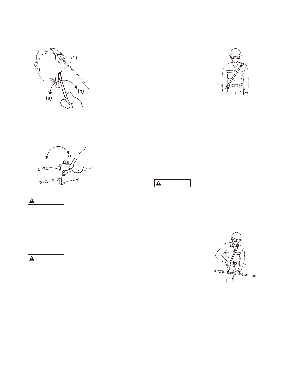
5. Always use the harness. Adjust the
harness for comfort before starting the
engine. The harness should be ad-
justed so the left hand can comfort-
ably hold the handlebar grip ap-
proximately waist high.
STARTING THE ENGINE
1. Keep bystanders and animals at least
15 m away from the operating point.
If you are approached, immediately
stop the engine.
2. The product is equipped with a cen-
trifugal clutch mechanism, so the
cutting attachment begins to rotate as
soon as the engine is started by put-
ting the throttle trigger into the start
position. When starting the engine,
place the product onto the ground in
a flat clear area and hold it firmly in
place so as to ensure that neither the
cutting part nor the throttle come into
contact with any obstacle when the
engine starts.
WARNING
Never place the throttle trigger into the
high-speed position when starting the
engine.
3. After starting the engine, check to
make sure that the cutting attachment
stops rotating when the throttle is
moved fully back to its original posi-
tion. If it continues to rotate even after
the throttle trigger has been moved
fully back, turn off the engine and take
the unit to your authorized ZENOAH
servicing dealer for repair.
USING THE PRODUCT
IMPORTANT
Cut only materials recommended by the
manufacturer. And use only for tasks
explained in the manual.
1. Grip the handles firmly with both
hands using your whole hand. Place
your feet slightly apart (slightly further
apart than the width of your shoulders)
so that your weight is distributed
evenly across both legs, and always
be sure to maintain a steady, even
posture while working.
2. Maintain the speed of the engine at
the level required to perform cutting
work, and never raise the speed of the
engine above the level necessary.
3. Never operate the pruner at an angle
greater than 60° in order to reduce the
risk of being struck by falling objects
during operation.
4. If the unit starts to shake or vibrate,
turn off the engine and check the
whole unit. Do not use it until the
trouble has been properly corrected.
5. Keep all parts of your body away from
rotating cutting attachment and hot
surfaces.
6. Never touch the muffler, spark plug,
or other metallic parts of the engine
while the engine is in operation or
immediately after shutting down the
engine. Doing so could result in seri-
ous burns or electrical shock.
WARNING
Approaching or contacting electric
power lines with the pruner may cause
serious injury death from electrocu-
tion. Electricity can jump from one
point to another by means arcing or
may be conducted through damp
branches. Maintain a clearance of at
least 15m between the pruner and any
electrical line carrying live current.
• IF SOMEONE COMES
1. Guard against hazardous situations
at all times. Warn adults to keep pets
and children away from the area. Be
careful if you are approached. Injury
may result from flying debris.
2. If someone calls out or otherwise inter-
rupts you while working, always be
sure to turn off the engine before turn-
ing around.
MAINTENANCE
1. In order to maintain your product in
proper working order, perform the
maintenance and checking opera-
tions described in the manual at
regular intervals.
2. Always be sure to turn off the engine
and disconnect the spark plug wire
before performing any maintenance
or checking procedures.
WARNING
The metallic parts reach high tem-
peratures immediately after stopping
the engine.
3. When replacing the cutting attach-
ment or any other part, or when re-
placing the oil or any lubricant, always
be sure to use only ZENOAH prod-
ucts or products which have been
certified by ZENOAH for use with
the ZENOAH product.
4. In the event that any part must be
replaced or any maintenance or repair
work not described in this manual
must be performed, please contact a
representative from the store nearest
ZENOAH authorized servicing dealer
for assistance.
5. Do not use any accessory or attach-
ment other than those bearing the
ZENOAH mark and recommended for
the unit.
6. Under no circumstances should you
ever take apart the product or alter it
in any way. Doing so might result in
the product becoming damaged dur-
ing operation or the product becom-
ing unable to operate properly.
5. For safe operation

GB-6
PSZ2610
HANDLING FUEL
1. The engine of the ZENOAH product
is designed to run on a mixed fuel,
which contains highly flammable
gasoline. Never store cans of fuel or
refill the tank of the unit in any place
where there is a boiler, stove, wood
fire, electrical sparks, welding sparks,
or any other source of heat or fire
which might ignite the fuel.
2. Never smoke while operating the unit
or refilling its fuel tank.
3. When refilling the tank, always turn off
the engine and allow it to cool down.
Take a careful look around to make
sure that there are no sparks or open
flames anywhere nearby before refu-
eling.
4. Wipe spilled fuel completely using a
dry rag if any fuel spillage occurs
during refueling.
5. After refueling, screw the fuel cap
back tightly onto the fuel tank and then
carry the unit to a spot 3 m or more
away from where it was refueled be-
fore turning on the engine.
TRANSPORTATION
1. When you finish cutting in one location
and wish to continue work in another
spot, turn off the engine, lift up the unit
and carry it paying attention to the
blade.
2. Never forget to place the protective
cover over the blades.
3. When hand-carrying the product,
cover over the cutting attachment if
necessary, lift up the product and
carry it paying attention to the cutting
attachment.
4. Never transport the product over
rough roads over long distances by
vehicle without removing all fuel from
the fuel tank. If doing so, fuel might
leak from the tank during transport.
Kickback and Pinching Safety
Precautions
Beware of kickback!
Kickback can occur whenever the tip of
the guide bar touches an object while the
saw is operating. Kickback may force the
bar up and back toward the operator with
lightning-like speed!
Beware of pinching.
Pinching the saw along the tip of the
guide bar may force the bar back rap-
idly toward the operator. Pinching can
occur whenever wood closes in around
the moving chain.
WARNING
Both kickback and pinching may cause
you to lose control of the pole pruner
which could result in serious personal
injury. Do not rely exclusively on the
safety device built into the pruner! You
must take several steps to keep your
jobs free from accident or injury:
1. Understand kickback and pinching!
You can reduce or eliminate the ele-
ment of surprise. Sudden surprises
contributes to accidents.
2. Keep a firm grip on the pole pruner
with both hands whenever the engine
is running. A firm grip will help you
reduce the affects of kickback and
pinching as well as maintain control
of the machine.
3. Make sure the area in which you are
cutting is free from obstructions. Do
not let the nose of the guide bar con-
tact a log, branch, or any other ob-
structions which could be hit while you
operation the pole pruner.
4. Cut at high engine speeds.
5. Follow the manufacturer’s instructions
for sharpening and maintaining the
chain.
6. Use only the replacement bar and
chain or equivalent as specified by
the manufacturer.
WARNING
• Makesurethechainandsprocketare
correctly adjusted before operating
the pruner (see page 9~10 for adjust-
ment procedures). Never attempt
chain adjustment with the engine run-
ning!
• Alwaysmakesurethecuttingattach-
ment is properly installed and firmly
tightened before operation.
• Neveruseacrackedorwarpedguide
bar: replace it with a serviceable one
and make sure it fits properly.
• Ifsawchainshouldbindfastinacut,
shut off the engine immediately. Push
the branch or tree to ease the bind
and free saw chain.
• Do not operate the pruner with the
muffler removed.
• Whencuttingalimbthatisunderten-
sion, be alert for springback so that
you will not be struck by the moving
limb.
• Alwaysstoptheengineimmediately
and check for damage if you strike a
foreign object or if the machine be-
comes tangled. Do not operate with
broken or damaged equipment.
IMPORTANT
• Donotmakeunauthorizedmodica-
tions or substitutions to the guide bar
or chain.
• Neverallowtheenginetorunathigh
RPM without a load. Doing so could
damage the engine.
• Keeptheprunerascleanaspossible.
Keep it free of loose vegetation, mud,
etc
5. For safe operation

GB-7
PSZ2610
G
B
6. Set up
MOUNTING ENGINE
1. Push the shaft tube toward the clutch housing and
rotate it by hand to check that the power transmission
shaft is engaged with the gears.
2. Insert the power transmission shaft housing into the
clutch housing until it bottoms, and align the position-
ing holes on the clutch housing and the shaft tube
and install the screw. When difficult to engage, twist
the engine slightly.
3. Fasten the clamp securely with two screws.
IMPORTANT
Tighten the screws gradually by turns.
CONNECTING THROTTLE WIRE
1. Remove the air cleaner cover.
2. Connect the end of the throttle wire to the joint on the
top of the carburetor.
CONNECTING SWITCH WIRES
• Connecttheswitchwiresbetweentheengineand
the main unit. Pair the wires of the same color.
ATTACHING THE PRUNING MECHANISM
(1)
(2)
(3)
(4)
(5)
(1) Tube (2) Transmission (3) Screw hole
(4) Fastening bolt (5) Bolt
1. Remove the cap on the end of the tube.
2. Remove the bolt screwed into the end of the trans-
mission.
3. Insert the end of the tube into transmission.
4. Line up the hole on the end of the transmission into
which the bolt is to be inserted with the screw hole
on the tube, and screw the bolt firmly in.
5. Using a wrench, screw the bolt provided to fix the
mechanism into place.
A standard package contains the items as shown be-
low.
(1) Guide bar (2) Saw chain
(3) Transmission (4) Sprocket
(5) Chain tension adjuster screw (6) Nut
(7) Chain tension adjuster nut (8) Chain cover
Install the guide bar and the saw chain on the transmis-
sion as follows.
WARNING
The saw chain has very sharp edges. Use protective
gloves for safety.
1. Loosen a nut and remove the chain cover.
2. Mount the guide bar then fit the saw chain around
the guide bar and sprocket.
WARNING
Pay attention to the correct direction of the saw
chain.
3. Fit the chain tension adjuster nut into the lower hole
of the guide bar, then install the chain cover, and
fasten the mounting nut to finger tightness.
(1) Hole
(2) Moving direction
(3) Chain cover

GB-8
PSZ2610
6. Set up
4. Adjust the chain tension by turning the chain tension
adjuster screw until the tie straps just touch the bot-
tom side of the bar rail.
(1) Chain tension adjuster
screw
(a) Loosen
(b) Tighten
5. Tighten the mounting nut securely with the bar tip
held up (TORQUE: 8.9 - 11.7 N.m./90 - 120 kg-cm).
Then check the saw chain for smooth rotation and
correct tension while moving it by hand. If necessary,
readjust.
(1) Tighten
WARNING
It is very important to maintain the proper chain
tension. Rapid wear of the guide bar or the chain
coming off easily can be caused by improper ten-
sion. Especially when using a new chain, take good
care of it since it should expand when first used.
HARNESS
WARNING
ALWAYS WEAR THE PROVIDED HARNESS WHEN
USING THE MACHINE!
Always make sure the machine is hooked securely
to the harness.
If you don’t, you will be unable to control the ma-
chine safely. This can result in injury to yourself or
others.
Never use a harness with a defective quick release
or any other damage.
HOW TO WEAR
1. Wear the provided harness without twisted bands,
with the hanger on your right side.
(1)
(Single harness)
(1) Hanger
BALANCE UNIT
1. Put on harness and attach unit to harness.
2. Depending on the working posture, slide clamp up or down
until unit balances and the harness fits your body.
QUICK RELEASE
The harness is equipped with a “QUICK RELEASE”
devise.
To release the machine from the harness in emergency
situations, please follow the procedure as explained
below.
WARNING
Make sure to check proper working of the QUICK
RELEASE device BEFORE operating the machine.
Make sure to hold the unit securely when using the
QUICK RELEASE.
While holding the unit by your left hand securely, press
both sides of the buckle.
(1)
(Single harness)
(1) Buckle

GB-9
PSZ2610
G
B
7. Fuel and chain oil
■FUEL
WARNING
• Gasoline is very flammable. Avoid smo king or
bringing any flame or sparks near fuel. Make sure
to stop the engine and allow it cool before refueling
the unit. Select outdoor bare ground for fueling and
move at least 3 m (10 ft) away from the fueling point
before starting the engine.
• The Zenoah engines are lubricated by oil specially
formulated for air-cooled 2-cycle gasoline engine use.
If Zenoah oil is not available, use an anti-oxidant
added quality oil expressly labeled for air-cooled
2-cycle engine use (JASO FC GRADE OIL or ISO EGC
GRADE).
• DonotuseBIAorTCW(2-strokewater-coolingtype)
mixed oil.
■RECOMMENDED MIXING RATIO
GASOLINE 50 : OIL 1
(when using ZENOAH genuine oil)
• Exhaust emission are controlled by the funda
mental engine parameters and components (eq.,
carburation, ignition timing and port timing) without
addition of any major hardware or the introduction
of an inert material during combustion.
• Theseenginesarecertiedtooperate onunleaded
gasoline.
• Make sure to use gasoline with a minimum octane
number of 89RON (USA/Canada: 87AL).
• If you use a gasoline of a lower octane value than
prescribed, there is a danger that the engine tem-
perature may rise and an engine problem such as
piston seizing may consequently occur.
• Unleaded gasoline is recommended to reduce the
contamination of the air for the sake of your health and
the environment.
• Poor quality gasolines or oils may damage sealing
rings, fuel lines or fuel tank of the engine.
■HOW TO MIX FUEL
WARNING
• Pay attention to agitation.
1. Measure out the quantities of gasoline and oil to be
mixed.
2. Put some of the gasoline into a clean, approved fuel
container.
3. Pour in all of the oil and agitate well.
4. Pour in the rest of gasoline and agitate again for at
least one minute. As some oils may be difficult to
agitate depending on oil ingredients, sufficient agita-
tion is necessary for the engine to last long. Be care-
ful that, if the agitation is insufficient, there is an in-
creased danger of early piston seizing due to abnor-
mally lean mixture.
5. Put a clear indication on the outside of the container
to avoid mixing up with gasoline or other containers.
6. Indicate the contents on outside of container for easy
identification.
■FUELING THE UNIT
1. Untwist and remove the fuel cap. Rest the cap on a
dustless place.
2. Put fuel into the fuel tank to 80% of the full capacity.
3. Fasten the fuel cap securely and wipe up any fuel
spillage around the unit.
WARNING
1. Select flat and bare ground for fueling.
2. Move at least 10 feet (3 meters) away from the
fueling point before starting the engine.
3. Stop the engine before refueling the unit. At that
time, be sure to sufficiently agitate the mixed
gasoline in the container.
■FOR YOUR ENGINE LIFE, AVOID:
1. FUEL WITH NO OIL (RAW GASOLINE) – It will cause
severe damage to the internal engine parts very
quickly.
2. GASOHOL – It can cause deterioration of rubber and/
or plastic parts and disruption of engine lubrication.
3. OIL FOR 4-CYCLE ENGINE USE – It can cause spark
plug fouling, exhaust port blocking, or piston ring
sticking.
4. Mixed fuels which have been left unused for a
period of one month or more may clog the carburetor
and result in the engine failing to operate properly.
5. In the case of storing the product for a long period of
time, clean the fuel tank after rendering it empty. Next,
activate the engine and empty the carburetor of the
composite fuel.
6. In the case of scrapping the used mixed oil container,
scrap it only at an authorized repository site.
NOTE
As for details of quality assurance, read the description
in the section Limited Warranty carefully. Moreover, nor-
mal wear and change in product with no functional influ-
ence are not covered by the warranty. Also, be careful
that, if the usage in the instruction manual is not observed
as to the mixed gasoline, etc. described therein, it may
not be covered by the warranty.
■Chain oil
Use motor oil SAE #10W-30 all year round or SAE
#30 - #40 in summer and SAE #20 in winter.
NOTE
Do not use wasted or regenerated oil that can cause
damage to the oil pump.

GB-10
PSZ2610
8. Operation
STARTING ENGINE
WARNING
The cutting head will start rotating upon the engine
starts.
1. Feed fuel and chain oil into their respective tanks
and tighten the caps securely.
(1)
(1) Fuel (2) Chain oil
2. Rest the unit on a flat, firm place. Keep the cutting
head off the ground and clear of surrounding objects,
as it will start rotating upon starting of the engine.
3. Push the primer pump several times until overflown
fuel flows out in the clear tube.
4. Move the choke lever to the closed position.
(1)
(2)
(3)
(1) Choke lever (2) Close (3) Open
5. Set the stop switch to the “-” position. Set the throttle
trigger to the start position (1 →2 →3).
Place the unit on a flat, firm place.
Keep the cutting head clear of everything around
it.
1
2
3
(1)
(1) Stop switch
6. While holding the unit firmly, pull out the starter rope
quickly until engine fires.
WARNING
The product is equipped with a centrifugal clutch
mechanism, so the cutting attachment begins to
rotate as soon as the engine is started by putting
the throttle trigger into the start position. When
starting the engine, place the product onto the
ground in a flat clear area and hold it firmly in place
so as to ensure that neither the cutting part nor the
throttle trigger come into contact with any obstacle
when the engine starts.
IMPORTANT
• Avoidpullingthe ropetoits endor returning itby
releasing the knob. Such actions can cause starter
failures.
7. Move the choke lever downward to open the choke.
And restart engine.
(1)
(2)
(3)
(1) Choke lever
(2) Close
(3) Open

GB-11
PSZ2610
G
B
8. Operation
8. Allow the engine to warm up for a several minutes
before starting operation.
NOTE
1. When restarting the engine immediately after stop-
ping it, leave the choke open.
2. Overchoking can make the engine hard to start due
to excess fuel. When the engine failed to start after
several attempts, open the choke and repeat pulling
the rope, or remove the spark plug and dry it.
STOPPING ENGINE
1. Release the throttle lever and run the engine for half
a minute.
2. Shift the ignition switch to the STOP position.
IMPORTANT
• Exceptforanemergency,avoidstoppingtheengine
while pulling the throttle lever.
• When it doesn’t stop at the stop switch, move the
choke lever to the closed position.
ADJUSTING THROTTLE CABLE
• Thenormalplayis1or2mmwhenmeasuredatthe
carburetor side end. Readjust with the cable ad-
juster as required and tighten the screw up.
(1)
(3)
(2)
(1) Cable adjuster
(2) 0.04in (1~2mm)
(3) Screw
ADJUSTING IDLING SPEED
(1)
(1) Idle speed adjuster
1. When the engine tends to stop frequently at idling
mode, turn the adjusting screw clockwise.
2. When the cutting head keeps rotating after releasing
the throttle trigger, turn the adjusting screw counter-
clockwise.
NOTE
• Warm up the engine before adjusting the idling
speed.
Checking oil supply
After starting the engine, run the chain at medium speed
and see if chain oil has scattered off, as shown in the
figure.
(1) Chain oil
NOTE
The oil reservoir has a capacity sufficient to provide
about 40 minutes of cutting time (when set to deliver
the minimum flow rate, or about as long as you’ll get
from a tank of fuel). Be sure to refill the oil tank every
time when refuelling the saw.

GB-12
PSZ2610
8. Operation
Adjusting Oil Flow Rate
WARNING
Never fill the oil reservoir nor adjust the oiler with
the engine running.
IMPORTANT
An increase in bar oil flow rate will speed oil consump-
tion, requiring more frequent checks on the oil reservoir.
To ensure sufficient lubrication, it may be necessary to
check the oil level more frequently than at fuel tank
refills.
The guide bar and chain are lubricated automatically
by a pump that operates whenever the chain rotates.
The pump is set at the factory to deliver a minimum flow
rate, but it can be adjusted in the field. A temporary
increase in oil flow is often desirable when cutting things
like hardwood or wood with a lot of pitch.
Adjust the pump as follows:
1. Stop the engine and make sure the stop switch is in
the OFF position.
2. Place the unit on its side with the oil reservoir up.
(1) Oil tank (2) Chain cover
IMPORTANT
The oil flow adjusting screw must be pressed in slightly
in order to turn. Failure to do so could damage the pump
and screw.
3. With a screwdriver, push in on the oil flow rate adjust-
ing screw and turn in the desired direction (there are
three incremental settings):
(a) Clockwise-decrease lubrication
(b) Counter clockwise-increase lubrication
(c) Middle
WARNING
• Always wear work gloves made of leather or some
other sturdy material when using the pruner.
• Falling branches may fall onto the face or into the
eyes, resulting in injuries, scratches, and cuts,
and for this reason you should always be sure to
wear a helmet and face protector when using your
pruner.

GB-13
PSZ2610
G
B
9. Maintenance
WARNING
• Make sure that the engine has stopped and is cool
before performing any service to the machine.
Contact with moving cutting head or hot muffler
may result in a personal injury.
AIR FILTER
• Theairlter,ifclogged,willreducetheengineper-
formance. Check and clean the filter element in
warm, soapy water as required. Dry completely
before installing. If the element is broken or shrunk,
replace with a new one.
(1)
(1) Air filter
FUEL FILTER
• Whentheenginerunsshortoffuelsupply,checkthe
fuel cap and the fuel filter for blockage.
(1)
(1) Fuel filter
SPARK PLUG
• Startingfailureandmisringareoftencausedbya
fouled spark plug. Clean the spark plug and check
that the plug gap is in the correct range. For a re-
placement plug, use the correct type specified by
ZENOAH.
0.6 - 0.7 mm
• REPLACEMENT PLUG IS A NGK CMR7H.
IMPORTANT
• Note that using any spark plug other than those
designated may result in the engine failing to operate
properly or in the engine becoming overheated and
damaged.
• Toinstallthesparkplug,rstturnthepluguntilitis
finger tight, then tighten it a quarter turn more with a
socket wrench.
TIGHTENING TORQUE: 9.8 - 11.8 N.m.
(1 - 1.2 kg.m.)
MUFFLER
WARNING
• Inspect periodically, the mufer for loose fasten-
ers, any damage or corrosion. If any sign of ex-
haust leakage is found, stop using the machine
and have it repaired immediately in the repair
specialty store.
• Note that failing to do so may result in the engine
catching on fire.
System/components Procedure Before
use
Every
25
hours
after
Every
50
hours
after
Every
100
hours
after
Note
ENGINE
fuel leaks, fuel spillage wipe out ✔
fuel tank, air filter, fuel filter inspect/clean ✔replace, if necessary
idle speed adjuster see adjusting idling
speed (p. 11) ✔replace carburetor
if necessary
spark plug clean and readjust
plug gap ✔GAP: 0.6 - 0.7 mm
replace, if necessary
intake air cooling vent clean ✔
SHAFT
throttle trigger, stop switch check operation ✔
transmission grease ✔
screws/nuts/bolts tighten/replace ✔ ✔ not adjusting screws
CUTTING UNIT
oiling port clean ✔ ✔
guide bar clean ✔
sprocket inspect/replace ✔
saw chain inspect/sharp ✔

GB-14
PSZ2610
9. Maintenance
SPARK ARRESTER
• The mufer is equipped with a spark arrester to
prevent red hot carbon from flying out of the exhaust
outlet. Periodically inspect and clean as necessary
with a wire brush in the repair specialty store.
(1)
(1) Spark arrester
INTAKE AIR COOLING VENT
WARNING
• Check the intake air cooling vent after every 25
hours of use for blockage, and remove any waste
which has attached itself to the machine.
IMPORTANT
• Ifwastegetsstuckandcausesblockagearoundthe
intake air cooling vent, it may cause the engine to
overheat, and that in turn may cause mechanical
failure on the part of the machine.
Intake air cooling vent
OILING PORT
Dismount the guide bar and check the oiling port for
clogging. (MA1)
(1)
(1) Oiling port
GUIDE BAR
Remove sawdust in the guide bar groove and the oiling
port.
(1) Groove (2) Oiling port
(Type: Sprocket nose)
Grease the nose sprocket from the feeding port on the
tip of the bar.
(1) Grease port (2) Sprocket
The guide bar rail should always be a square. Check
for wear of the guide bar rail. Apply a ruler to the bar
and the outside of a cutter. If a gap is observed between
them, the guide bar rail is normal. Otherwise, the guide
bar rail is worn. Such a bar needs to be corrected or
replaced.
(1) Ruler (2) Gap
(3) No gap (4) Chain tilts

GB-15
PSZ2610
G
B
After every cutter has been set, check the depth gauge
and file it to the proper level as illustrated. (MA7)
(1) Appropriate gauge checker
(2) Make the shoulder round
(3) Depth gauge standard
0.25" (0.65 mm)
WARNING
Be sure to round off the front edge to reduce the
chance of kickback or tie-strap breakage.
Make sure every cutter has the same length and edge
angles as illustrated.
(4) Cutter length (5) Filing angle
(6) Side plate angle (7) Top plate cutting angle
TRANSMISSION
The reduction gears are lubricated by multipurpose,
lithium-based grease in the transmission.
Supply new grease every 25 hours of use or more often
depending on the job condition.
When adding lubricant, use a grease gun to insert lu-
bricant into the three grease nipples located on the
transmission.
(1) Grease fitting
9. Maintenance
SPROCKET
Check for extensive wear, and replace it when the teeth
are worn over 0.3 mm.
0.3 mm
(1) Sprocket
SAW CHAIN
WARNING
It is very important for smooth and safe operation
to keep the cutters always sharp.
Your cutters need to be sharpened when:
• Sawdustbecomespowder-like.
• Youneedextraforcetosawin.
• Thecutwaydoesnotgostraight.
• Vibrationincreases.
• Fuelconsumptionincreases.
Cutter setting standards:
WARNING
Be sure to wear safety gloves.
Before filing:
• Makesurethesawchainisheldsecurely.
• Makesuretheengineisstopped.
• Usearoundleofpropersizeforyourchain.
Chain type : 90SG
File size : 5/32 in (4.0 mm)
Place your file on the cutter and push straightforward.
Keep the file position as illustrated.

GB-16
PSZ2610
11. Disposal
• Whenyoudisposeofthemachine,donotdisassemblethe
machine.
• Whenyoudisposeofthemachine,fuel,oil,besuretofollow
your local regulations.
10. Storage
Limited warranty
Aged fuel is one of major causes of engine starting failure.
Before storing the unit, empty the fuel tank and run the engine
until it uses all the fuel left in the fuel line and the carburetor.
Store the unit indoor taking necessary measures for rust preven-
tion.
Should any failure occur on the product under normal operating
conditions within the applicable warranty period, the failed part
will be replaced or repaired free of charge by a ZENOAH au-
thorized dealer.
WARRANTY PERIOD: Six (6) months after purchased by end-
user subject to 12 months from produced month. (30 days If
used for rental purpose)
THE PURCHASER SHALL BEAR COSTS OF TRANSPORTING
THE UNIT TO AND FROM THE ZENOAH DEALER.
THE PURCHASER SHALL NOT BE CHARGED FOR DIAGNOS-
TIC LABOR WHICH LEADS TO THE DETERMINATION THAT A
WARRANTED PART IS DEFECTIVE, IF THE DIAGNOSTIC WORK
IS PERFORMED AT THE ZENOAH DEALER.
THE PURCHASER OR OWNER IS RESPONSIBLE FOR THE
PERFORMANCE OF THE REQUIRED MAINTENANCE AS DE-
FINED BY THE MANUFACTURER IN THE OWNER/OPERATOR
MANUAL.
ANY WARRANTED PART WHICH IS NOT SCHEDULED FOR
REPLACEMENT AS REQUIRED MAINTENANCE, OR WHICH IS
SCHEDULED ONLY FOR REGULAR INSPECTION TO THE EF-
FECT OF REPAIR OR “REPLACE AS NECESSARY” SHALL BE
WARRANTED FOR THE WARRANTY PERIOD. ANY WAR-
RANTED PART WHICH IS SCHEDULED FOR REPLACEMENT
AS REQUIRED MAINTENANCE SHALL BE WARRANTED FOR
THE PERIOD OF TIME UP TO THE FIRST SCHEDULED RE-
PLACEMENT POINT FOR THE PART.
ANY REPLACEMENT PART THAT IS EQUIVALENT IN PERFOR-
MANCE AND DULABILITY MAY BE USED IN NON-WARRANTY
MAINTENANCE OR REPAIRS, AND SHALL NOT REDUCE THE
WARRANTY OBLIGATION OF THE COMPANY.
THE COMPANY IS LIABLE FOR DAMAGES TO OTHER ENGINE
COMPONENTS CAUSED BY THE FAILURE OF A WARRANTED
PART STILL UNDER WARRANTY.
THE WARRANTY DOES NOT APPLY TO THOSE UNITS WHICH
HAVE BEEN DAMAGED BY NEGLIGENCE OF INSTRUCTION
LISTED IN THE OWNER/OPERATOR MANUAL FOR PROPER
USE AND MAINTENANCE OF THE UNITS ACCIDENT MISHAN-
DLING, ALTERATION, ABUSE, IMPROPER LUBRICATION, USE
OF ANY PARTS OR ACCESSORIES OTHER THAN THOSE
SPECIFIED BY THE COMPANY, OR OTHER CAUSES BEYOND
THE COMPANY’S CONTROL.
THIS WARRANTY DOES NOT COVER THOSE PARTS RE-
PLACED BY NORMAL WEAR OR HARMLESS CHANGES IN
THEIR APPEARANCE.
THERE ARE NO OTHER EXPRESS WARRANTIES.
ANY IMPLIED WARRANTY is limited to the duration of the
limited warranty. Otherwise, this limited warranty is in lieu of all
other expressed or implied warranties, including any warranty
of FITNESS FOR A PARTICULAR PURPOSE OR USE and any
implied warranty MERCHANTABILITY otherwise applicable to
this product.
LIABILITIES FOR INCIDENTAL OR CONSEQUENTIAL DAM-
AGE UNDER ANY AND ALL WARRANTIES ARE EXCLUD-
ED.
IF YOU NEED TO OBTAIN MORE INFORMATION, PLEASE CALL
YOUR NEAREST SERVICE CENTER, OR CHECK PLEASE ZE-
NOAH WEB SITE http://www.zenoah.net
12. Troubleshooting guide
Case 1. Starting failure
CHECK PROBABLE CAUSES ACTION
fuel tank →incorrect fuel →drain it and use correct fuel
fuel filter →fuel filter is clogged →clean
carburetor adjustment screw →out of normal range →adjust to normal range
sparking (no spark) →spark plug is fouled/wet →clean/dry
→plug gap is incorrect →correct (GAP: 0.6 - 0.7 mm)
spark plug →disconnected →retighten
Case 2. Engine starts but does not keep running/hard re-starting
CHECK PROBABLE CAUSES ACTION
fuel tank →incorrect fuel or staled fuel →drain it and use correct fuel
carburetor adjustment screw →out of normal range →adjust to normal range
muffler, cylinder (exhaust port) →carbon is built-up →consult with the repair specialty store
air cleaner →clogged with dust →air blow or wash
cylinder fin, fan cover →clogged with dust →consult with the repair specialty store
When your unit seems to need further service, please consult with our ZENOAH service shop in your area.
Other manuals for PSZ2610
1
Table of contents
Other Zenoah Pole Saw manuals