Zimmer HF150-003 User guide

www.zimmer-group.de
INSTALLATION
AND OPERATING
INSTRUCTION
HF150-003
Motor spindle
DDOC00746
THE KNOW-HOW FACTORY

INSTALLATION AND OPERATING INSTRUCTIONS: Motor spindle, HF150-003 series
Zimmer GmbH •Im Salmenkopf 5 •77866 Rheinau, Germany •+49 7844 9138 0 • +49 7844 9138 80 •www.zimmer-group.com
2
EN / 2020-10-22DDOC00746 / -
Article number: HF150-003
Date of issue: 2020-10-22
Index: -
Most recent index date: -
Document language: EN
Foreword
Dear Customer,
Thank you for the condence you have placed in us by selecting our motor spindle.
Our motor spindle represents the current state of technology in terms of development and design.
In order to utilize the full performance capability of this motor spindle and maintain it in a state of constant readiness and
eciency, operating personnel require in-depth training from our experts.
These installation and operating instructions are a constituent part of the operating instructions of the machine in which this
incomplete machine is installed and shall be kept available for operating personnel to use at all times in accordance with
the Machinery Directive.
For this reason, always keep the installation and operating instructions along with the operating manual at an accessible
work post near the machine.
Name and address of the manufacturer:
Zimmer GmbH
Im Salmenkopf 5, 77866 Rheinau, Germany
+49 7844 9138 0
+49 7844 9138 80
info@zimmer-group.de
www.zimmer-group.com
For any follow-on orders, please contact Zimmer Customer Service.

INSTALLATION AND OPERATING INSTRUCTIONS: Motor spindle, HF150-003 series
3
Zimmer GmbH •Im Salmenkopf 5 •77866 Rheinau, Germany •+49 7844 9138 0 • +49 7844 9138 80 •www.zimmer-group.com
EN / 2020-10-22DDOC00746 / -
Glossary
Abbreviation Explanation
HTS Hollow taper shank
MSDS Material safety datasheets
PTC Positive temperature coecient/thermistor
SBT Silicon-based thermistor
MQL Minimum quantity lubrication
MQCL Minimum quantity cooling lubrication
►Handling instructions
ÖConsequences or additional information of an instruction
• Bulleted list 1
–Bulleted list 2

INSTALLATION AND OPERATING INSTRUCTIONS: Motor spindle, HF150-003 series
Zimmer GmbH •Im Salmenkopf 5 •77866 Rheinau, Germany •+49 7844 9138 0 • +49 7844 9138 80 •www.zimmer-group.com
4
EN / 2020-10-22DDOC00746 / -
Content
1 Supporting documents ......................................................................................................................................................... 6
2 Notices and graphics in the installation and operating instructions ................................................................................. 6
2.1 Hazard levels of warning notices ...............................................................................................................................................................................6
3 Handling/Transport/Scope of delivery................................................................................................................................ 7
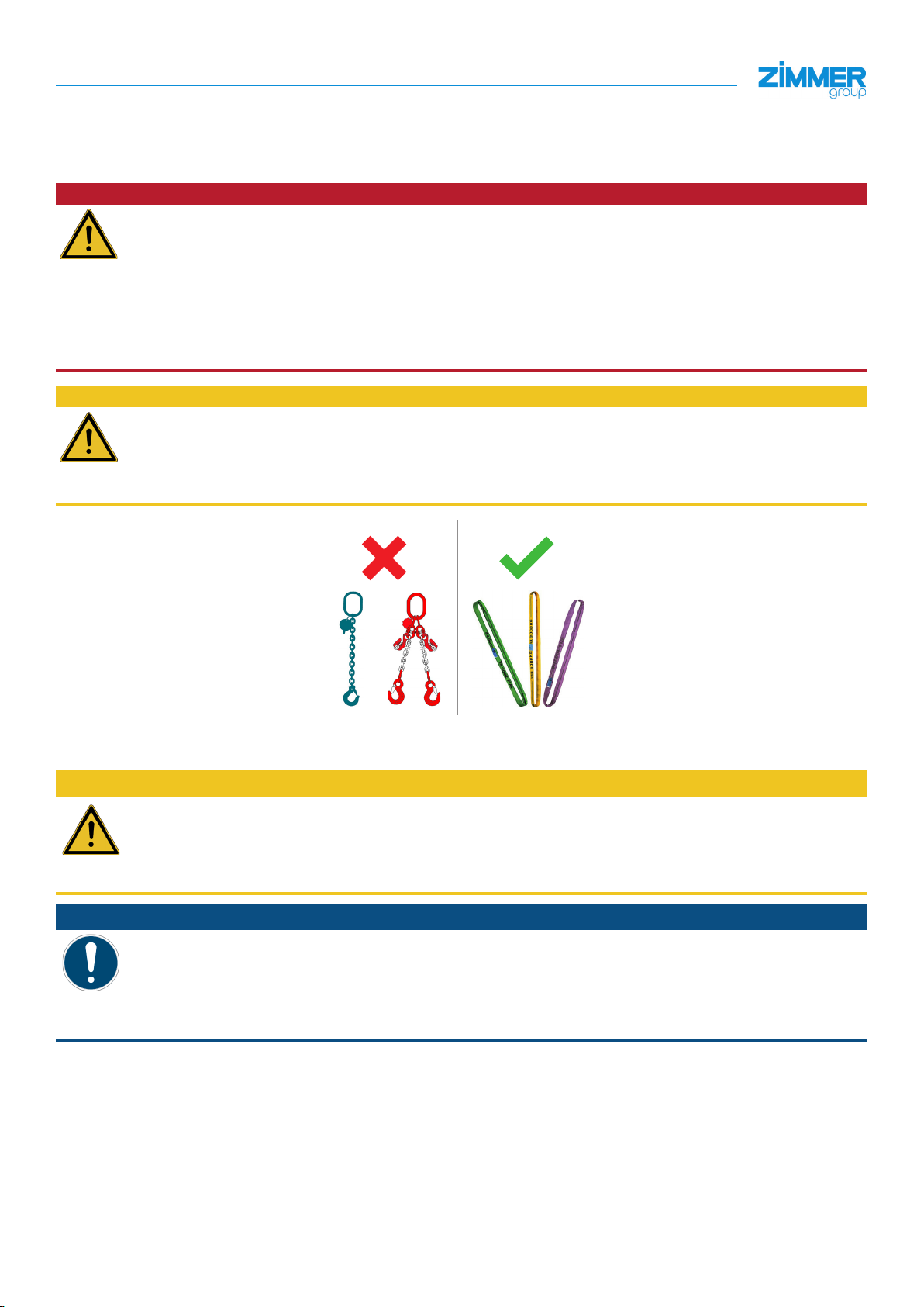
3.1 Handling .......................................................................................................................................................................................................................7
3.2 Transportation data .....................................................................................................................................................................................................7
3.3 Scope of delivery .........................................................................................................................................................................................................7
4 Safety notes ........................................................................................................................................................................... 8
5 Proper use ............................................................................................................................................................................. 9
6 Personnel qualication ......................................................................................................................................................... 9
7 Product description ............................................................................................................................................................10
7.1 Type plate ...................................................................................................................................................................................................................10
7.2 Functional description ..............................................................................................................................................................................................10
7.3 Design of the motor spindle .....................................................................................................................................................................................11
8 Technical data .....................................................................................................................................................................12
8.1 Motor ..........................................................................................................................................................................................................................12
8.2 Clamping state ...........................................................................................................................................................................................................12
8.3 Standstill monitoring .................................................................................................................................................................................................12
8.4 Use of thermistors .....................................................................................................................................................................................................12
8.5 Rotary encoder ..........................................................................................................................................................................................................13
9 Installation ............................................................................................................................................................................14
9.1 Safety notes ...............................................................................................................................................................................................................14
9.2 General installation information ...............................................................................................................................................................................15
9.3 Installing the motor spindle ......................................................................................................................................................................................15
9.4 Installing the attachment part ...................................................................................................................................................................................16
9.5 Installing the power supply .......................................................................................................................................................................................17
9.6 Installing the electrical connections ........................................................................................................................................................................18
9.7 Installing the uid connections ................................................................................................................................................................................19
9.8 Installing the cooling system ....................................................................................................................................................................................19
9.8.1 Cooling duct connections ..........................................................................................................................................................................21
9.8.2 Requirements for the screw-on surface ....................................................................................................................................................21
9.8.3 Cooling unit .................................................................................................................................................................................................21
9.8.4 Requirements for the cooling circuit .........................................................................................................................................................21
9.9 Tool holder .................................................................................................................................................................................................................22
10 Commissioning ...................................................................................................................................................................23
10.1 Safety notes ...............................................................................................................................................................................................................23
10.2 Checking operational readiness ..............................................................................................................................................................................24
10.3 Tool interface (setting dimensions/clamping force) ...............................................................................................................................................25
10.3.1 Checking the clamping force ....................................................................................................................................................................26
10.4 Checking the tool interface (analog sensor and switching states) ........................................................................................................................26
10.5 Commissioning the cooling circuit ..........................................................................................................................................................................27
10.6 Thermistors ................................................................................................................................................................................................................27
10.6.1 PTC130 thermistor ......................................................................................................................................................................................27
10.6.2 PT1000 thermistor.......................................................................................................................................................................................27
10.7 Grease distribution ....................................................................................................................................................................................................28
11 Operation .............................................................................................................................................................................28
11.1 Safety notes ...............................................................................................................................................................................................................28
11.2 Warm-up cycle at the start of work ..........................................................................................................................................................................29

INSTALLATION AND OPERATING INSTRUCTIONS: Motor spindle, HF150-003 series
5
Zimmer GmbH •Im Salmenkopf 5 •77866 Rheinau, Germany •+49 7844 9138 0 • +49 7844 9138 80 •www.zimmer-group.com
EN / 2020-10-22DDOC00746 / -
11.3 Operating temperatures ............................................................................................................................................................................................29
11.4 Preparing for operation .............................................................................................................................................................................................30
11.4.1 Machining tools ...........................................................................................................................................................................................30
11.4.2 Tool data ......................................................................................................................................................................................................30
11.4.3 Feed rate ......................................................................................................................................................................................................30
11.4.4 Angular acceleration ...................................................................................................................................................................................30
11.5 Removing from operation .........................................................................................................................................................................................30
12 Maintenance ........................................................................................................................................................................ 31
12.1 Safety note .................................................................................................................................................................................................................31
12.2 Cleaning agents .........................................................................................................................................................................................................32
12.3 Denitions of maintenance work ..............................................................................................................................................................................32
12.3.1 Visual inspection of the motor spindle ......................................................................................................................................................32
12.3.2 Inspection of the motor spindle .................................................................................................................................................................32
12.3.3 Maintenance of the motor spindle .............................................................................................................................................................32
12.3.4 Overhaul of the motor spindle ....................................................................................................................................................................32
12.4 Maintenance plan ......................................................................................................................................................................................................33
13 Disassembly for decommissioning .................................................................................................................................... 34
14 Decommissioning and disposal ......................................................................................................................................... 34
15 Cleaning/preservation ........................................................................................................................................................ 34
16 Storage .................................................................................................................................................................................35
17 Recommissioning ............................................................................................................................................................... 35
18 Provision of spare parts ...................................................................................................................................................... 35
19 Troubleshooting .................................................................................................................................................................. 36
20 Appendix ..............................................................................................................................................................................37
21 RoHS declaration ................................................................................................................................................................ 38
22 REACH declaration ............................................................................................................................................................. 38
23 Declaration of Incorporation .............................................................................................................................................. 39
24 Declaration of conformity ................................................................................................................................................... 40

INSTALLATION AND OPERATING INSTRUCTIONS: Motor spindle, HF150-003 series
Zimmer GmbH •Im Salmenkopf 5 •77866 Rheinau, Germany •+49 7844 9138 0 • +49 7844 9138 80 •www.zimmer-group.com
6
EN / 2020-10-22DDOC00746 / -
1 Supporting documents
NOTICE
Read through the installation and operating instructions carefully before installing the product!
The installation and operating instructions contain important notes for your personal safety. They must be read
and understood by all persons who work with or handle the product during any phase
of the product life cycle.
The documents listed below are available for download on our website www.zimmer-group.com
. Only those documents currently available on the website are valid.
• Drawing
• Specication
• CAD data
• General Terms and Conditions of Business with specications for the warranty entitlement
2 Notices and graphics in the installation and operating instructions
The individual hazard levels, notices and warnings are marked with signal words.
2.1 Hazard levels of warning notices
DANGER
This notice warns of an imminent danger to the life and health of people. Ignoring these notices can result in
serious injury or death!
►You absolutely must comply with the described measures for avoiding these dangers.
ÖThe warning symbols are assigned according to the type of danger.
WARNING
This notice warns of a situation that is potentially hazardous to personal health. Ignoring these notices can result
in serious injury or damage to health.
►You absolutely must comply with the described measures for avoiding these dangers.
ÖThe warning symbols are assigned according to the type of danger.
CAUTION
This notice warns of a situation that is potentially hazardous for personnel or that may result in material or
environmental damage. Ignoring these notices may result in slight, temporary injuries or damage to the product
or to the environment.
►You absolutely must comply with the described measures for avoiding these dangers.
ÖThe warning symbols are assigned according to the type of danger.
NOTICE
General notices contain usage tips and valuable information, but no warnings of dangers to health.
INFORMATION
This category contains useful tips for handling the product eciently. Failure to observe will not lead to damage
to the product. This information does not include any information relevant to health and workplace safety.

INSTALLATION AND OPERATING INSTRUCTIONS: Motor spindle, HF150-003 series
7
Zimmer GmbH •Im Salmenkopf 5 •77866 Rheinau, Germany •+49 7844 9138 0 • +49 7844 9138 80 •www.zimmer-group.com
EN / 2020-10-22DDOC00746 / -
3 Handling/Transport/Scope of delivery
3.1 Handling
DANGER
Injuries from suspended loads
Improper handling of suspended loads will cause serious injury or death!
Observe the following points:
ÖUse suitable hoisting devices.
ÖWear appropriate personal protective equipment.
ÖAlways keep an adequate safety distance from suspended loads.
ÖNever walk underneath a suspended load.
CAUTION
Material damage if unsuitable hoisting devices and attachment equipment are used
Unsuitable hoisting devices or attachment equipment may damage the product.
ÖDo not use any chains or steel cables.
ÖUse only tested lifting belts with sucient load capacity.
3.2 Transportation data
CAUTION:
Improper transportation
Improper handling of the transportation box will cause transport damage to the motor spindle!
ÖDo not tilt the transportation box.
ÖAvoid powerful vibrations and impacts.
NOTICE:
Transportation temperature
During transport of the motor spindle, the temperature must not exceed or fall below the following range:
• - 10 °C
• +60 °C
The motor spindle is always delivered in a reusable transportation box.
Remove the packaging of the motor spindle only to the extent necessary for internal forwarding.
3.3 Scope of delivery
• Motor spindle
• Installation and operating instructions
• Maintenance plan (constituent part of the installation and operating instructions)
• Transportation box
• Supporting documents (see Section “20 Appendix”)

INSTALLATION AND OPERATING INSTRUCTIONS: Motor spindle, HF150-003 series
Zimmer GmbH •Im Salmenkopf 5 •77866 Rheinau, Germany •+49 7844 9138 0 • +49 7844 9138 80 •www.zimmer-group.com
8
EN / 2020-10-22DDOC00746 / -
4 Safety notes
CAUTION:
Risk of injury in the event of improper installation, commissioning or maintenance and improper use
Non-compliance may result in severe injuries!
Installation, commissioning, maintenance and repairs may only be performed by qualied specialists in
accordance with these installation and operating instructions.
The motor spindle is state-of-the-art. It is installed on industrial machines and is used to hold tools. The following
are examples of situations in which the motor spindle may pose a hazard:
• It is not properly installed or maintained
• It is not used for its intended purpose
• Local regulations (legislation, ordinances, guidelines), such as the EC Machinery Directive, accident
prevention regulations and the installation and operating instructions, are not observed.
The motor spindle may be used only as intended and in accordance with the technical data. Zimmer GmbH shall
accept no liability for any damage caused by improper use.
Any use other than the intended use requires written approval from Zimmer GmbH.
Make sure that the power supply is disconnected before you install, retool or maintain the motor spindle.
Zimmer GmbH recommends performing maintenance tasks, renovation work or attachment work outside of the
machine's danger zone when possible.
When commissioning or testing, make sure that the motor spindle cannot be actuated by mistake.
Modications to the motor spindle, such as adding drilled holes or threads, may be made only with prior
approval from Zimmer GmbH.
The specied maintenance intervals are to be observed; also refer to the "Maintenance" section. When the
motor spindle is used under extreme conditions, the maintenance interval must be adapted.
Use of the motor spindle under extreme conditions, such as aggressive liquids and abrasive dust, is subject to
prior approval from Zimmer GmbH.
Do not reach into the operating range of the motor spindle!
Notes and handling regulations for electrostatically sensitive components
Electrostatically sensitive components are individual components, integrated circuits or assemblies that can be
damaged by electrostatic elds or electrostatic discharge.
ÖWhen handling electrostatic components, make sure that personnel, the work area and the packaging are all
fully grounded!
ÖElectronic components may be touched by personnel only in appropriately identied areas with conductive
ooring and only if:
• These persons are grounded by means of special bracelets.
• These persons wear shoes that are suitable and approved for discharging electrostatic charges.
ÖElectronic assemblies must not be brought into contact with plastics and parts of clothing that contain
plastic.
ÖElectronic assemblies may only be placed on conductive underlays.
ÖElectronic assemblies must not be installed in the vicinity of data back-up devices or monitors (monitor
distance > 100 mm).
ÖMeasurements may be performed on electronic assemblies only if:
• The measuring instrument is grounded (e.g. via a ground conductor)
• The measuring head is momentarily discharged before measuring with a oating measuring instrument.

INSTALLATION AND OPERATING INSTRUCTIONS: Motor spindle, HF150-003 series
9
Zimmer GmbH •Im Salmenkopf 5 •77866 Rheinau, Germany •+49 7844 9138 0 • +49 7844 9138 80 •www.zimmer-group.com
EN / 2020-10-22DDOC00746 / -
5 Proper use
NOTICE:
The motor spindle is to be used only in its original state with its original accessories, without any unauthorized
changes and within the scope of its dened parameters for use.
Zimmer GmbH shall accept no liability for any damage caused by improper use.
The motor spindle is designed for installation in machines with separating safety equipment in accordance with EN ISO
14119 and for the following production methods:
• Machining with geometrically dened cuts/dry machining (DIN 8589-0) for non-abrasive materials.
• Drilling, counterboring, reaming (DIN 8589-2)
• Milling (DIN 8589-3)
• Grinding (DIN 8589-0)
The motor spindle is used to hold and drive cutting tools.
Permitted materials:
• Wood
• Plastics
• Light metals, non-ferrous metals or comparable materials
Any other or more extensive use is improper. Zimmer GmbH accepts no liability for any damage resulting from improper
use. The operator/user bears sole responsibility.
6 Personnel qualication
DANGER:
Intervention is not permitted and can lead to serious injuries!
ÖWarranty and disclaimer
Installation, commissioning and maintenance may only be performed by qualied personnel.
These personnel must have read and understood the installation and operating instructions in full.

INSTALLATION AND OPERATING INSTRUCTIONS: Motor spindle, HF150-003 series
Zimmer GmbH •Im Salmenkopf 5 •77866 Rheinau, Germany •+49 7844 9138 0 • +49 7844 9138 80 •www.zimmer-group.com
10
EN / 2020-10-22DDOC00746 / -
7 Product description
7.1 Type plate
A type plate is attached to the housing of the motor spindle.
The article number and the serial number are shown on the type
plate.
►The serial number should be assigned to the project.
ÖArticle number: am
ÖSerial number: an
ÖInterface ao
ÖMaximum speed: ap
XXX
XXX
am
an
XXX
XXX
ao
ap
7.2 Functional description
The product is directly driven by a three-phase motor.
The product is operated by means of a frequency converter. An inductive proximity switch is installed for speed sensor
monitoring and standstill monitoring (optional: a sin/cos 1Vss). The heat created by the motor must be discharged by a
suitable cooling system. The product features corresponding internal cooling ducts.
The loosening unit is designed for automatic tool exchange and has an inductive analog sensor with corresponding
evaluation electronics for monitoring.
A high-resolution rotary encoder can be installed as an option for speed control/standstill monitoring (Lenord + Bauer).

INSTALLATION AND OPERATING INSTRUCTIONS: Motor spindle, HF150-003 series
11
Zimmer GmbH •Im Salmenkopf 5 •77866 Rheinau, Germany •+49 7844 9138 0 • +49 7844 9138 80 •www.zimmer-group.com
EN / 2020-10-22DDOC00746 / -
7.3 Design of the motor spindle
1Type plate 9Piston housing
2Unit interface/front side (optional) bl Piston housing/intermediate ange with sensors
3Spindle neck bm Motor spindle housing
4HSK taper bn Installation positions with connecting thread
5HSK clamping set bo Display with LED display
6HSK plane face bp Coolant connections
7Power supply bq Pneumatic connections
8Plug housing br PE connection/ground conductor
bs Sealing air connection (optional)
1
2
3
4
5
6
8
9
bl
bm
7
bn
2
bo
7
bp
bq
bp
br
bs

INSTALLATION AND OPERATING INSTRUCTIONS: Motor spindle, HF150-003 series
Zimmer GmbH •Im Salmenkopf 5 •77866 Rheinau, Germany •+49 7844 9138 0 • +49 7844 9138 80 •www.zimmer-group.com
12
EN / 2020-10-22DDOC00746 / -
8 Technical data
INFORMATION:
For technical data, please refer to the specications or visit our website.
Zimmer Customer Service is available to provide you with assistance if you have any further questions.
8.1 Motor
DANGER:
Risk of fatal injury and material damage when operating without a frequency converter!
The motor must never be connected directly to the power supply without the use of a frequency converter.
INFORMATION:
The motor must be operated via a frequency converter.
For technical data, please refer to the specications.
You can request the setting parameters for the converter from Zimmer GmbH.
8.2 Clamping state
The clamping state of the tool holder is detected by a sensor and is transmitted to the machine control system as digital
signals.
Refer to the specications for the technical design of the sensors.
Three clamping states are available:
• Clamped without tool
• Clamped with tool
• Tool unclamped
The circuit diagram of the clamping states is provided on the technical datasheet.
8.3 Standstill monitoring
DANGER:
Risk of fatal injury and material damage when operating without the cam signals of the standstill
monitoring!
A sensor records the speed of the motor spindle.
The signal can be used by the machine control system for standstill monitoring.
ÖOperate the motor spindle only if standstill monitoring is available.
Refer to the specications for the number of cams.
8.4 Use of thermistors
NOTICE:
At least one of the three thermistors (PTC/KTY/PT1000) must be connected to the control system in order to
prevent damage resulting from overheating.
ZimmerGmbH is not liable for damage due to improper or faulty use of the thermistors.
For further information on thermistors, refer to Section “11 Operation”.

INSTALLATION AND OPERATING INSTRUCTIONS: Motor spindle, HF150-003 series
13
Zimmer GmbH •Im Salmenkopf 5 •77866 Rheinau, Germany •+49 7844 9138 0 • +49 7844 9138 80 •www.zimmer-group.com
EN / 2020-10-22DDOC00746 / -
8.5 Rotary encoder
DANGER:
Risk of fatal injury when operating or changing tools without standstill monitoring!
Material damage when operating without rotation monitoring
If the frequency converter is switched on, the standstill (speed = 0 U/min) of the spindle shaft (standstill
monitoring) must be continuously observed.
This particularly applies to the following:
• Persons within the separating safety equipment area
• Maintenance and repair tasks
• Manual tool exchange
• Automatic tool exchange
• Commissioning
►Operate the motor spindle only when the standstill monitoring is actively evaluated and monitored.
►Establish a logical link between the signals of the rotary encoder and their control system.
ÖIt must not be possible for any person to be able to stand inside the safety device – or to enter it – while
the motor spindle is rotating.
Risk of fatal injury and damage to the product when operating without signals from the speed sensor
The speed signal must be generated from the installed sine/cosine encoder with two independent speed
signals. Otherwise, there is a risk of fatal injury and the possibility of causing damage to the motor spindle as a
result of over-revving.
►Operate the motor spindle only if speed signals are available.
NOTICE:
For detailed information on the rotary encoder, refer to the third-party company instructions in Section “20
Appendix”.
The installed rotary encoder generates a sine/cosine signal for rotating the spindle shaft. As a result, it is possible to
achieve high-resolution vector control of the motor spindle. When the spindle shaft is at a standstill, the rotary encoder does
not generate any signals.
ÖStandstill monitoring
The transmitter wheel has a reference mark for the spindle shaft.

INSTALLATION AND OPERATING INSTRUCTIONS: Motor spindle, HF150-003 series
Zimmer GmbH •Im Salmenkopf 5 •77866 Rheinau, Germany •+49 7844 9138 0 • +49 7844 9138 80 •www.zimmer-group.com
14
EN / 2020-10-22DDOC00746 / -
9 Installation
9.1 Safety notes
WARNING:
Delivery, unpacking and transport to the installation site
The motor spindle must be inspected for any possible damage in transit after delivery to the installation site and
after unpacking. Transportation within the company is permitted only in the original packaging or in comparable
packaging.
Potential consequences of damage in transit include serious personal injury or signicant material damage.
►A quality assessment must be performed upon delivery of the motor spindle.
►Log the results.
Quality evaluation criteria:
• Damage to the packaging
• Damaged or defective connections
• Visible damage to the housing or impact marks
• Surface damage on the mounting surface, unit interface and front side
• Damage to the taper, clamping system or plane face
Damage in transit after installation
If the motor spindle has already been installed in the superordinate machine or system, the motor spindle
must be checked for damage in transit after each time it is transported. It is absolutely necessary to avoid any
vibrations or impact.
Potential consequences of damage in transit include serious personal injury or signicant material damage.
Risk of injury in case of unexpected movement of the machine or system into which the motor spindle is
being installed.
►Switch off the power supply to the machine before all work.
►Secure the machine against being switched on unintentionally.
►Check the machine for any residual energy.
Installation can cause a health hazard and material damage
Improper hoisting will cause personal injury or material damage:
►The motor spindle must only be lifted by qualied personnel using suitable equipment.
►Note the weight of the unit or check the handling diagram.
►Wear suitable personal protective equipment.
CAUTION:
Material damage if incorrect connection values are used
The connection values provided in the specications must not be exceeded!
ÖDamage to the motor spindle
• All connection values must be measured on site and compared to the specications.
• It is absolutely necessary for the values to match.
NOTICE:
Switch off the power supply before any assembly and installation work.
The operator must ensure that all safety regulations are observed.
• National regulations
• Local regulations

INSTALLATION AND OPERATING INSTRUCTIONS: Motor spindle, HF150-003 series
15
Zimmer GmbH •Im Salmenkopf 5 •77866 Rheinau, Germany •+49 7844 9138 0 • +49 7844 9138 80 •www.zimmer-group.com
EN / 2020-10-22DDOC00746 / -
9.2 General installation information
The motor spindle must be installed on a mounting surface in accordance with the specications for atness.
Requirements for the mounting surface:
• Maximum atness of 0.02 mm
• Surface roughness Ra1.6
• Cleanliness of the mounting surfaces for the motor spindle and mounting pieces (motor spindle grounding)
Further installation information:
• The mounting screws and the pins are not included in the scope of delivery.
• Strength class of the mounting screws at least 8.8 (DIN EN ISO 4762)
ÖZimmer GmbH recommends verifying the permitted load-carrying capacity of the required screw connections in
accordance with VDI 2230.
• Make sure the mounting piece is suciently rigid.
INFORMATION:
When installing the motor spindle, you must ensure that there is sucient clearance space around the motor
spindle.
Observe the following measures:
• Ensure a sucient amount of air circulation or cooling
ÖEnsure sucient dimensions for the machining area – room size/enclosure.
ÖProvide a sucient fresh air supply.
• Do not install any additional heat sources at the motor spindle
• Avoid soiling (fan suction)
Zimmer GmbH recommends a clearance space of 100 mm around the motor spindle.
Zimmer Customer Service is available to provide you with assistance if you have any further questions.
9.3 Installing the motor spindle
The product is installed on the mounting piece using the installation surface.
The following work steps must be observed during installation:
►Position the product on the screw-on surface.
►Mount the product to the screw-on surface using the mounting screws bp.
bp

INSTALLATION AND OPERATING INSTRUCTIONS: Motor spindle, HF150-003 series
Zimmer GmbH •Im Salmenkopf 5 •77866 Rheinau, Germany •+49 7844 9138 0 • +49 7844 9138 80 •www.zimmer-group.com
16
EN / 2020-10-22DDOC00746 / -
9.4 Installing the attachment part
As an option, a mechanically customized interface can be added to the motor spindle (e.g. to hold a C-axis or unit carrier).
With attachment part Without attachment part
The mechanical interface is customized to match the specic motor spindle and therefore must not be replaced or mounted
to a different motor spindle.
CAUTION:
Damage to the motor spindle
The customized interface guarantees the function of the product.
ÖThe mechanically customized interface must not be dismantled!
Material damage and malfunction of the motor spindle
Attachments parts on the housing and spindle neck must not introduce any additional forces or vibrations to the
motor spindle.

INSTALLATION AND OPERATING INSTRUCTIONS: Motor spindle, HF150-003 series
17
Zimmer GmbH •Im Salmenkopf 5 •77866 Rheinau, Germany •+49 7844 9138 0 • +49 7844 9138 80 •www.zimmer-group.com
EN / 2020-10-22DDOC00746 / -
9.5 Installing the power supply
CAUTION:
Malfunction due to improper power supply installation
Installing the power supply correctly ensures that the motor spindle will function properly.
ÖAlways install exible power supply lines.
NOTICE:
Function of the motor spindle is ensured
The function of the motor spindle is ensured if:
• The power supply lines have adequate dimensions
• The power supply lines are used that are as short as possible and shielded throughout their entire length
If the power supply lines do not have adequate dimensions, the motor spindle might have an insucient supply.
ÖFault or damage to the motor spindle
INFORMATION:
The bending radius of the power supply lines must not fall below the minimum value!
Cables that are hanging freely must be axed!
ÖExcessive movement stress or crushing must be avoided.
Refer to the technical datasheet for the wiring diagrams, plug coding and uid connections.
E
XD1 XG3 (optional)
XG2
PE
A
KR
AZAZ
F
SPL
ARelease the tool XD1 Power connection and signal
connection
AZ Clamp the tool XG2 Signal connection
SPL Sealing air XG3 Position sensor and speed sensor
(optional)
KR Cone cleaning F/E Zu- und Rückführung Kühlsystem
PE Schutzleiteranschluss
NOTICE:
ÖUse compressed air in accordance with DIN ISO 8573-1 [3:4:3].

INSTALLATION AND OPERATING INSTRUCTIONS: Motor spindle, HF150-003 series
Zimmer GmbH •Im Salmenkopf 5 •77866 Rheinau, Germany •+49 7844 9138 0 • +49 7844 9138 80 •www.zimmer-group.com
18
EN / 2020-10-22DDOC00746 / -
9.6 Installing the electrical connections
DANGER:
Risk of fatal injury due to hazardous voltage!
As a general rule, the electrical connections must not be carrying voltage when they are installed!
ÖAll work on the electrical system must be performed when it is not carrying voltage!
CAUTION:
Malfunction and material damage due to improper installation of the electrical connections
Insert the electrical connections to the motor spindle securely!
ÖDuring assembly of the electrical connections, it is important to ensure that the pins of the motor spindle's
plug contacts are properly oriented and are not damaged/bent.
Faulty connection of the grounding wire will cause a health hazard and material damage
Observe the measures for protection against electrical shock.
ÖConnect the motor spindle's ground conductor and the machine.
ÖPersonnel may work near the electrical components only if they are properly and suciently grounded!
►Personnel are grounded by means of an ESD bracelet!
►Personnel must wear ESD shoes or ESD shoe grounding strips!
NOTICE:
Non-compliance may result in material damage
In order to ground the motor spindle reliably, the ground conductor and the housing of the motor spindle must
be connected by means of a separate cable.
ÖThere must be no electrical connection between the housing of the motor spindle and the electrical
connections!
Grounding the motor spindle is recommended if ESD-sensitive parts come into contact with the motor spindle.
Grounding is also recommended in applications that require high EMC shielding.

INSTALLATION AND OPERATING INSTRUCTIONS: Motor spindle, HF150-003 series
19
Zimmer GmbH •Im Salmenkopf 5 •77866 Rheinau, Germany •+49 7844 9138 0 • +49 7844 9138 80 •www.zimmer-group.com
EN / 2020-10-22DDOC00746 / -
9.7 Installing the uid connections
CAUTION:
Material damage due to unltered compressed air
Compressed air that is insuciently or incorrectly ltered and lubricated can cause the failure of units and
pneumatic components resulting from the penetration of dust, dirt or condensation water.
ÖSelect a suitable lter depending on the use of the product.
NOTICE:
Close off any unused pneumatic connections with suitable dummy plugs.
The authorized pneumatic connections that are available can be found in the accessories list, which is available
on our website. The necessary ordering information can also be found there.
ÖUse compressed air in accordance with DIN ISO 8573-1 [3:4:3].
ÖFor operating pressures, please refer to the specications.
You can obtain detailed information and corresponding supporting dimensions for your design from the
Technical Datasheet.
To optimally supply the product with the operational media, the media are transferred directly via the rear side interface of
the product.
Check the connection pressures and ow rates in accordance with specications and design your mounting piece
accordingly.
9.8 Installing the cooling system
CAUTION:
Health hazard due to coolant/antifreeze
ÖCoolant/antifreeze is dangerous to your health
ÖObserve the manufacturer's safety instructions
ÖAvoid skin contact
ÖWear personal protective equipment
Material damage if incorrect coolant media are used
The use of unsuitable or inadequate or incorrectly prepared coolant causes the failure of power units and
components.
ÖCavitation/corrosion damage
Additionally, heat insulating deposits develop on heat-transferring components, which can lead to excessive
heating and ultimately to motor failure.
ÖWhile using the product, observe the information provided by the coolant manufacturer at all times.
ÖWhile using the product, ensure a sucient ll level of the cooling unit at all times.
Property damage from using cooling lubricants
ÖCooling lubricants must NOT be used!
NOTICE:
The coolant ltration must lie within the following range:
Ö<100 μm

INSTALLATION AND OPERATING INSTRUCTIONS: Motor spindle, HF150-003 series
Zimmer GmbH •Im Salmenkopf 5 •77866 Rheinau, Germany •+49 7844 9138 0 • +49 7844 9138 80 •www.zimmer-group.com
20
EN / 2020-10-22DDOC00746 / -
Cooling system
The cooling system must meet the requirements for the intended use.
Component parts of the cooling system for the product include:
• Connecting lines (use a line with a large cross-section)
• Coolant (observe pH value)
• Cooling unit
• Attachment structure/motor spindle
The cooling system must be implemented as a closed system!
ÖDo not use an open cooling basin.
ÖUse under exclusion of oxygen.
ÖThe coolant must be available to the cooling circuit in the dened quantity and temperature.
pH value of the coolant
The coolant medium must meet the requirements for the intended use. Unsuitable coolant can lead to thermally insulating
deposits on parts that transfer heat. Zimmer GmbH accepts no liability for any resulting malfunctions or damage.
Zimmer GmbH recommends the use of “Cool-Core Ready” from Motorex, “SK3301.960” from Rittal or a comparable
coolant. All trials and test runs were carried out with one of the coolants specied above.
Incorrect pH value of the coolant
The coolant must be changed if the pH value is not between 6.5 and 8.5. Otherwise, damage to or impairment of the
cooling circuit may result. The coolant ltration must lie within the prescribed range.
Use of the coolant
The local approvals, guidelines and laws apply for the use of coolant.
Material specications of the product
INFORMATION:
The owner/operator must check whether its coolant is suitable for the material composition of the product.
Zimmer GmbH accepts no liability for any damage that may result from use of unsuitable coolants.
Component Material
Housing/cooling jacket AlMgSi1/AW-6082
Connector supports X5CrNi18-10/1.4301/V2A
Connection tting Brass, chemically nickel-plated
Seals FKM/Viton®
Table of contents
Popular Engine manuals by other brands

DANA
DANA BREVINI E Series Installation and maintenance manual

AZALEA AVIATION
AZALEA AVIATION SPYDER 100 HP Assembly manual

Controls
Controls J1939 iT4 product manual

Gerreka
Gerreka BUL BL33 Quick installation and programming guide

Detroit Diesel
Detroit Diesel 4000 Series Service manual

Dynabrade
Dynabrade Dynangle II 14308 Assembly instructions